Strontech Intel Haswell Series User manual

User's Manual
ECB-H81C11S
Intel Haswell Series
Motherboard
Motherboard
400-2009-08
http://www.strontech.com
Industrial Leadrt In Embedded Computing

Disclaimer
The intellectual property of this manual belongs to our company. The ownership of all of the
products, including accessories and software etc. belong to our company. No one is permitted to
copy, change, or translate without our written permission.
We compiled this manual based on our careful attitude, but we can not guarantee the accuracy
of the contents. This manual is purely technical documentation, without any hint or other
meanings, and we won't commit users' misunderstanding of the typesetting error.
Our products are in continuous improvement and updating, Therefore, we retain the right that
we won't give notice to the users in future.
Copyright
All of the trademark in this manual belong to their own registered company.
All of the products name is only for identication, its title belongs to its manufacturer or brand
owner.

Table of Contents
Chapter 1 Introduction.............................................................................. 4
1.1 Package Checklist.....................................................................................................4
1.2 Specications ..........................................................................................................5
1.3 Mainboard Layout ....................................................................................................6
1.4 Connecting Rear Panel I/O Devices............................................................................7
Chapter 2 Hardware Setup..........................................................................8
2.1 Installing Rear Panel I/O Devices ..............................................................................8
2.2 Installing the Mainboard to a Computer Chassis.........................................................8
2.3 Installation of the CPU and CPU Cooler...................................................................8
2.4 Installation of Memory Modules..............................................................................10
2.5 Connecting Peripheral Devices.................................................................................11
2.5.1 Serial ATA Connectors........................................................................................................11
2.5.2 MSATA and MPCIE slots.......................................................................................................11
Chapter 3 Jumpers & Headers Setup..........................................................12
3.1 Jumper Settings and introduction................................................................................12
3.2 CMOS Memory Clearing Header.................................................................................12
3.3 Jumpers Setting......................................................................................................13
3.4 Front Panel Switches & Indicators Headers...............................................................13
3.5 FUSB1 & USB20_3 Extended Interface.........................................................................14
3.6 HDD_PWR1/2(SATA POWER Interface) and JDCIN(DC POWER Interface)..................14
3.7 FAN Power Connectors............................................................................................15
3.8 HDMI_CON Connector...............................................................................................15
3.9 VGA_CON Connector ................................................................................................16
3.10 LVDS_CON Connector..............................................................................................16
3.11 INVERTER1 Connector.............................................................................................17
3.12 JLVDS Connector.....................................................................................................17
3.13 JGPIO Connector....................................................................................................18
3.14 Front Panel Audio..................................................................................................18
3.15 SPEAKERS Connector..............................................................................................19
3.16 JCOM1 Connector................................................................................................19
Chapter 4 BIOS Setup Utility......................................................................20
4.1 About BIOS Setup.............................................................................................……20
4.2 To Run
BIO S Setup
..................................................................................................20
4.3 About CMOS...........................................................................................................20
4.4 The POST (Power On Self Test).................................................................................20
4.5 BIOS Setup-CMOS Setup Utility.................................................................................21
4.5.1 CMOS Setup Utility............................................................................................…21
4.5.2 Control Keys.............................................………..........................................……22
4.5.3 Main ...........................................................…….......….…………....…...….....…23
4.5.4 Advanced..................................................................….....................………....…23
4.5.5 Chipset…..............................................................………...................................30
4.5.6 Boot…..................................................................…………............................…32
4.5.7 Security…...........................................................……........………..............…......33
Chapter 5 Driver Installation.....................................................................34
Appendix:
Toxic and hazardous substances or elements logo
.......................35

- 4 -
ECB-H81C11S User's Manual
Chapter 1 Introduction
1.1 Package Checklist
Thank you for choosing our products.
Before using your product, please make sure your packaging is complete, if there have
• Motherboard x 1
• SATA date Cable x 1
• SATA Power Cable x 1
• Rear panel IO x 1
• User's Manual x 1
• Driver x 1
The above accessories and speci cations are only for reference, we reserve the modify rights.
- 5 -
ECB-H81C11S User's Manual
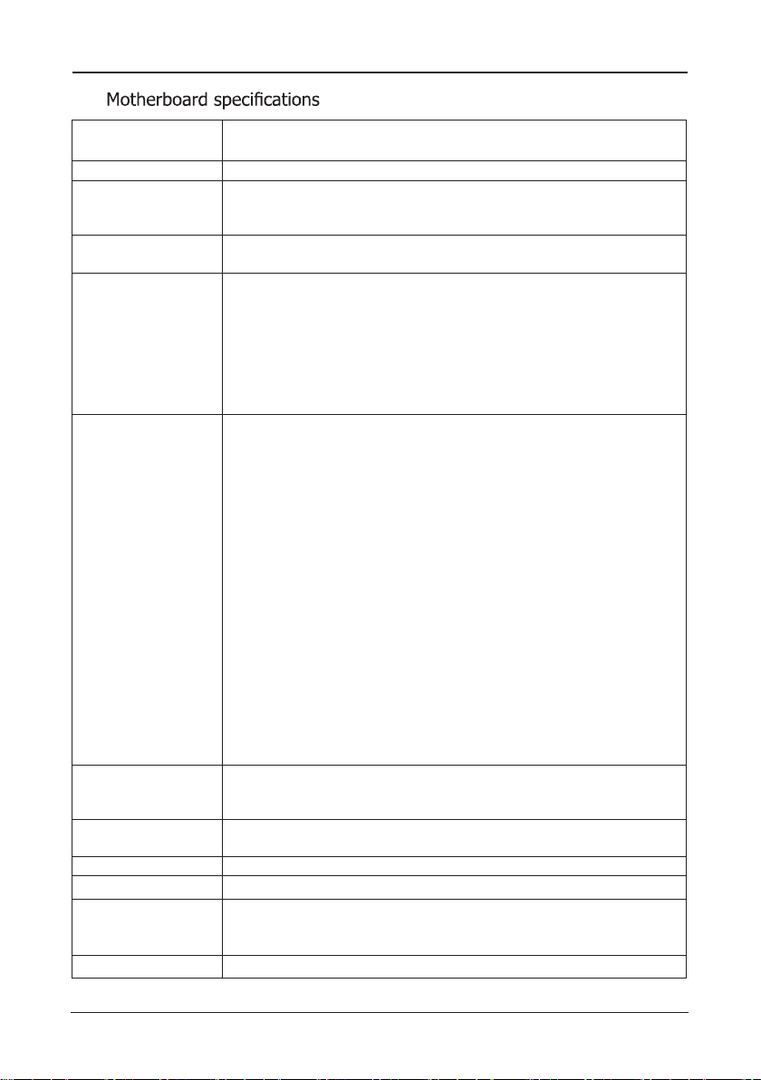
1.2
CPU - Support LGA1150 socket for Intel® 4th generation CoreTM i3/i5
/i7,Pentium®,Celeron®series processors
Chipet - Adopt Intel® H81 chipset
Memory
- 2 X 204-pin DDRIII SO-DIMM solts
- Support DDRIII SO-DIMM 1066/1333/1600MHz memory module
- The max memory capicity is up to 16GB
Expansion slots - 1 x MSATA slot
- 1 x MPCIE slot
Rear Panel I/O
- 1 x PJ1 power connector(DC Power)
- 1 x HDMI connector
- 1 x VGA connector
- 2 x USB 2.0 interfaces,backwards compatibility USB 1.1
- 2 x USB 3.0 interfaces,backwards compatibility USB 2.0/1.1
- 1 x RJ45 connector
- 2 x audio connectors(F_MIC/F_OUT)
- 1 x Optical digital audio interface (SPDIF)
Internal
Connectors
- 1 x 4-pin ATX_12V power connector(JDCIN )
- 1 x 9-pinUSB2.0 headers for additional 2 USB 2.0 connectors
- 1 x 5-pinUSB2.0 headers for additional 1 USB 2.0 connector
- 2 x SATA3.0 connectors
- 2 x HDD_PWR connectors
- 1 x Front panel switches connector
- 1 x Front Panel audio connectors
- 2 x Fan connectors
- 1 x JLVDS jumper(Supports VGA and HDMI with
asynchronous display )
- 1 x 16-pin HDMI_CON connector
- 1 x 30-pin LVDS_CON connector
- 1 x 12-pin VGA_CON connector
- 1 x JGPIO connector
- 1 x JCOM1 connector
- 1 x Speakers connector
- 1 x 6_pin INVERTER1 connector
- 1 x JME jumper
- 1 x CLR_COMS jumper
- 1 x LCD_PWR jumper
BIOS/POWER
Management
- Support advanced power management ACPI,Monitor CPU
temperture ,fan speed ,system voltage in real time
- Wakeup By LAN, Power-on boot,watchdog function,etc.
Audio - Onboard 4 Channel HD Audio Codec
- Front audio connector, Optical digital connector
LAN - 1 x 10/100/1000Mbps NIC connector
Form Factor - Mini-ITX(170mm * 170mm) architecture
Working Environment
- Working temperture :0~60。C
- Working Moisture :5%~90% No Frost
- Storage temperture :-20~70。C
Operating system - Windows7/8/8.1/Linux
- 6 -
ECB-H81C11S User's Manual
PJ 1
HDMI
VGA1
USB1
LAN1
USB2
F_MIC
SPDIF1
FAUDIO
SPEAKERS JCOM1
BIOS
CLR_CMOS
JME
MPCIE
MSATA
BAT
OC_AGV N
OC_IMDH N
JDCIN USB20_3SATA1 SATA2 HDD_PWR2 HDD_PWR1 FPANELCPU_FAN SYS_FAN
VL OC_SD N
EVNI TR RE 11
LJ DV S
IPGJ O
FUSB1
F_OUT
DIMM2
DIMM1
L RWP_DC
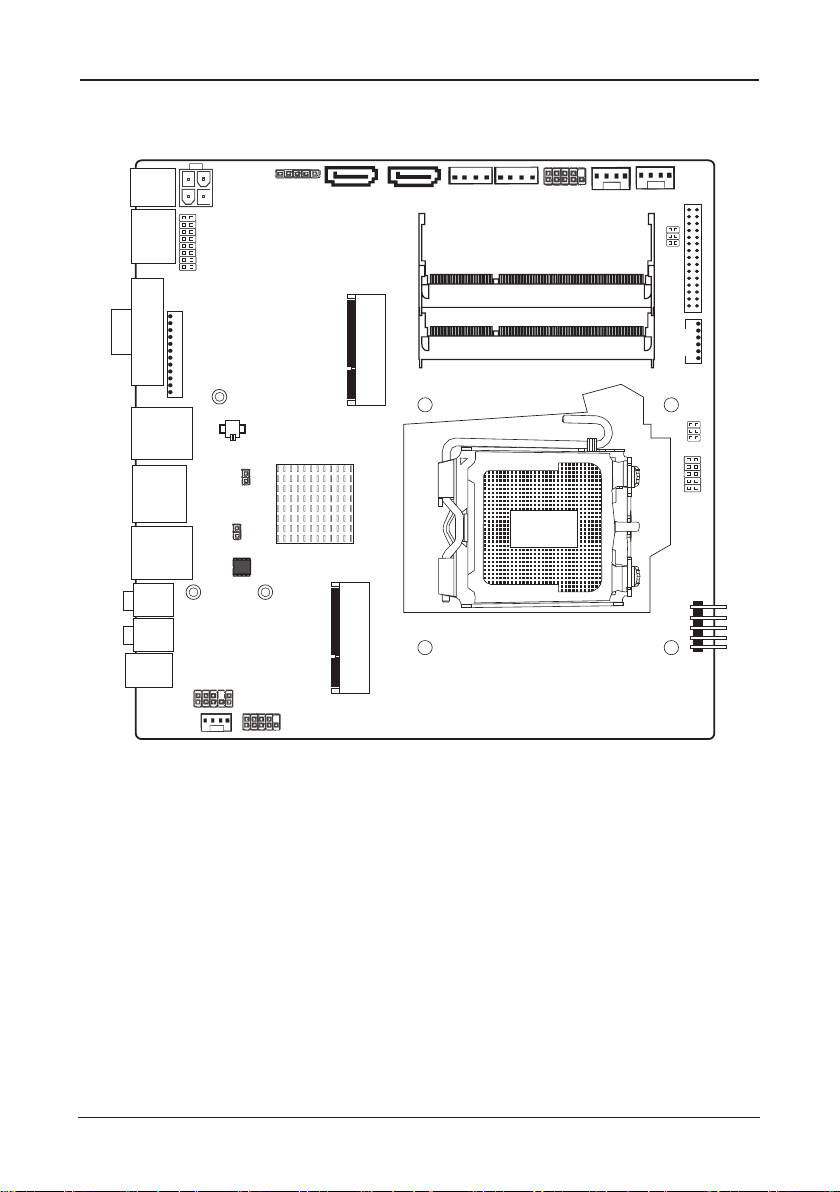
1.3 Motherboard Layout
(This picture is only for reference)

- 7 -
ECB-H81C11S User's Manual
VGA
HDM LI AN
USB3.0 F_MIC
PJ 1 USB2.0 F_OUT SPDIF1
1.4 Connecting Rear Panel I/O Devices
(This picture is only for reference)
• PJ1:
12V/19V DC Power interface
• HDMI:
Connects to multimedia devices of HDMI protocol
• VGA:
Connects to a monitor's VGA input
• USB3.0(blue):
USB3.0connector,backwards compatibility USB 2.0/1.1
• USB2.0(black):
USB2.0connector,backwards compatibility USB1.1
• LAN:
The LAN port allows the motherboard to connect to a local area network by means
of a network hub.
• F_MIC:
This jack is used to connect an external microphone
• F_OUT:
This jack is used to connect to the front left and right channel speakers of
the audio system
• SPDIF1:
This jack is Optical digital audio output interface ,which can be used to connect to
the front left and right channel speakers of the audio system
- 8 -
ECB-H81C11S User's Manual
Chapter 2 Hardware Setup
2.1
Installing
I/O Panel
It can block the transmission of electric RF, protect the internal components, and promote
after installing this panel. Before installing motherboard, you need to install this panel. If
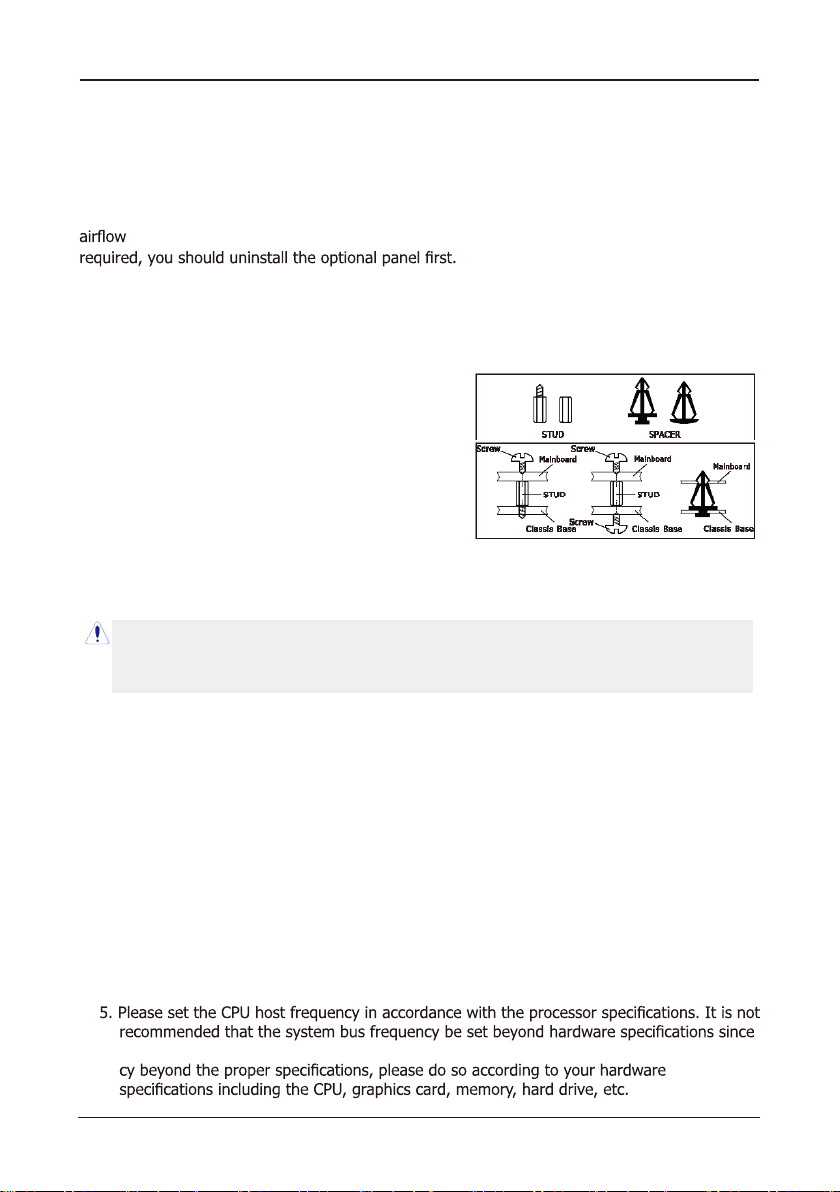
2.2 Installing the Mainboard
Most computer chassis have a base with many mounting holes to allow the mainboard to
be securely attached, and at the same time, prevent the system from short circuits. There
are two ways to attach the mainboard to the
chassis base: (1) with studs, or (2) with spacers.
Basically, the best way to attach the board is with
studs. Only if you are unable to do this should you
attach the board with spacers. Line up the holes on
the board with the mounting holes on the chassis.
If the holes line up and there are screw holes, you
can attach the board with studs. If the holes line
up and there are only slots, you can only attach with
spacers. Take the tip of the spacers and insert them
into the slots. After doing this to all the slots, you can slide the board into position aligned
with slots. After the board has been positioned, check to make sure everything is OK before
putting the chassis back on.
To install this mainboard:
1. Locate all the screw holes on the mainboard and the chassis base.
2. Place all the studs or spacers needed on the chassis base and have them tightened.
3. Face the mainboard’s I/O ports toward the chassis’s rear panel.
4. Line up all the mainboard’s screw holes with those studs or spacers on the chassis.
5. Install the mainboard with screws and have them tightened.
Always power off the computer and unplug the AC power cord before adding or removing
any peripheral or component. Failing to do so may cause severe damage to your
mainboard and/or peripherals. Plug in the AC power cord only after you have carefully
checked everything.
2.3 Installation of the CPU and CPU Cooler
Before installing the CPU, please comply with the following conditions:
1. Please make sure that the mainboard supports the CPU.
2. Please take note of the one indentedcorner of the CPU. If you install the CPUin the wrong
direction, the CPU will not insert properly. If this occurs, please change the insert direction
of the CPU.
3. Please add an even layer of heat sink paste between the CPU and CPU cooler.
4. Please make sure the CPU cooler is installed on the CPU prior to system use, otherwise
overheating and permanent damage of the CPU may occur.
it does not meet the required standards for the peripherals. If you wish to set the frequen-

- 9 -
ECB-H81C11S User's Manual
2.3.1 Installation of the CPU (These pictures are only for reference)
1. Open the socket lever by
pushing the lever down and
away from the socket .
2. Lift the load plate and remove the plastic protective
socket cover. Do not touch the socket contacts and do not
discard the protective socket cover. Always replace with the
protective socket cover if the processor is being removed
from the socket.
3.Position the CPU over
the socket, ensuring that
the gold triangle is on the
bottom-left corner of the
socket, and then fit the
socket alignment keys into
the CPU notches. (marked
with circle)
5. Insert the load lever under the retention tab.
4. Close the load plate, and then push down the load lever,
please ensure that the front edge of the load plate slides
UNDER the retention knob (marked with circle).
2.3.2 Installation of the CPU Cooler
For proper installation, please kindly refer to the instruction manuals of your CPU Cooler.
- 10 -
ECB-H81C11S User's Manual
2.4 Installing Memory Module
This motherboard provides two 204-pin DDRIII SO-DIMM slots.
Before starting the installation, please read the following warning messages:
2. Before installing or removing memory, make sure that the computer is turned off;
3. The memory is designed with fool-proof marker, if you insert with wrong direction, it can
not be inserted.
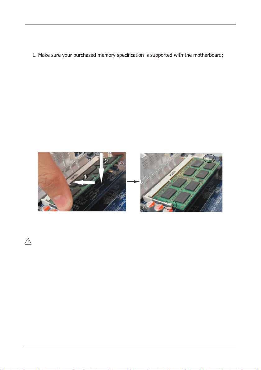
Installing memory:
1. Before installing or removing memory, please turn off the power and unplug the AC cable.
2. Carefully grasp both ends of memory, and do not touch the metal contacts.
3. Align the memory to slots, and pay attention to the direction.
4. Inclining 30 degrees and insert, then press down untill you hear the "clicking" sound (to
avoid any demage, your strengh must be gentle).
5. To remove the memory, push out both latch of DIMM slot at the same time, and take it
out.
Memory installation illustration (only for reference):
:Static will demage the electronic components of computer and memory, when doing
above step, you should contact with a grounded metial object to remove the static from your
body.
- 11 -
ECB-H81C11S User's Manual
PJ 1
HDMI
VGA1
USB1
LAN1
USB2
F_MIC
SPDIF1
FAUDIO
SPEAKERS JCOM1
BIOS
CLR_CMOS
JME
MPCIE
MSATA
BAT
OC_AGV N
OC_IMDH N
JDCIN USB20_3 SATA1 SATA2
HDD_PWR2 HDD_PWR1
FPANELCPU_FAN SYS_ FAN
VL OC_SD N
EVNI TR RE 11
LJ DV S
IPGJ O
FUSB1
F_OUT
DIMM2
DIMM1
L RWP_DC
PJ 1
HDMI
VGA1
USB1
LAN1
USB2
F_MIC
SPDIF1
FAUDIO
SPEAKERS JCOM1
BIOS
CLR_CMOS
JME
MPCIE
MSATA
BAT
OC_AGV N
OC_IMDH N
JDCIN USB20_3SATA1 SATA2 HDD_PWR2 HDD_PWR 1 FPANELCPU_FAN SYS_FA N
VL OC_SD N
EVNI TR RE 11
LJ DV S
IPGJ O
FUSB1
F_OUT
DIMM2
DIMM1
L RWP_DC
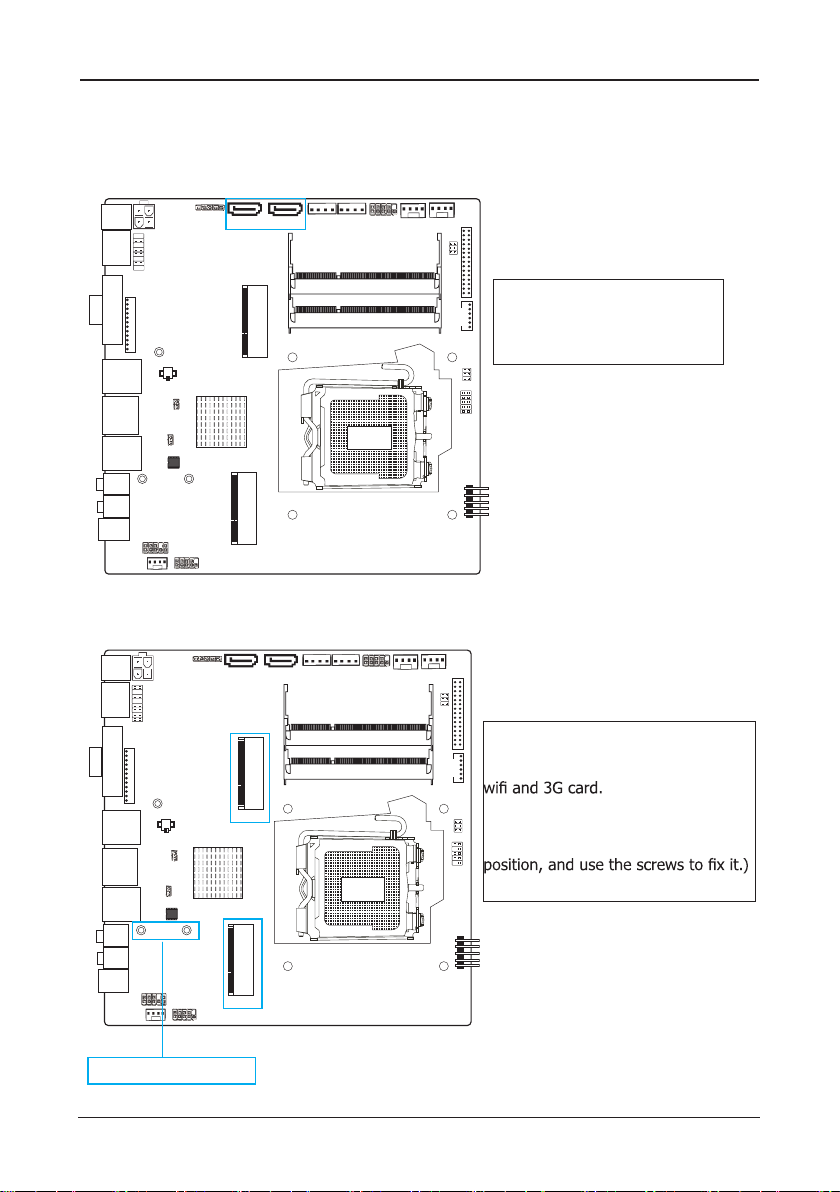
2.5.2 MSATA and MPCIE slots
2.5.1 Serial ATA Connectors
2.5 Connect with External Devices
The Serial ATA connectors can
connect to Serial ATA hardware
or other corresponding devices
when use Serial ATA cable。
MSATA slot is long card, It supports
SSD.
MPCIE slot is long card ,It supports
(While installing, incline it 30 degrees
and insert,then press down to bolt
Fix the screw antennas
- 12 -
ECB-H81C11S User's Manual
Chapter 3 Jumpers & Headers Setup
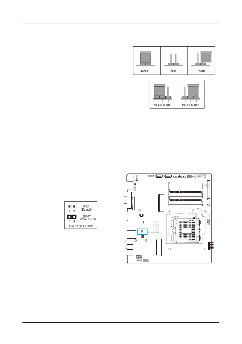
3.1 Checking Jumper Settings
• 2-pin jumper: Plug the jumper cap onto both
pins will make it CLOSE (SHORT). Remove the
cap or plug it on another pins (keep for future
use) will activate the jumper.
• 3-pin jumper: Plug the jumper cap onto pin
1~2 or pin 2~3 will make it CLOSE (SHORT).
shorted by plugging the jumper cap in.
How to identify the PIN1?
Please check the Motherboard carefully, the PIN1
is marked by "1", white thick line or white triangle.
3.2 CMOS Memory Clearing Header(JBAT)
When: (a) the CMOS data demaged, (b) you forgot the supervisor or password of BIOS,
(c) you are unable to boot-up because the frenquency of CPU was incorrectly, or (d) there
have modifications on CPU or memory modules, means you need to unplug the CMOS
header.
It uses a jumper cap to clear the CMOS setup, and reset the BIOS value to default.
• Pins 1 and 2 open circuit (Default): Normal situation
• Pins 1 and 2 shorted: Clear CMOS setup
To clear the CMOS setup and set to default values:
1. Power off the system.
2. Plug the jumper cap to pin 1-2, and wait for 3-5 seconds, then plug the cap back to pin
1-2.
3. Power on the system.
4. If the frequency of CPU set incorrect, please press the <Del> button to enter the BIOS
setup menu after powering on system.
5. Reset the running speed of CPU to default or to suitable value.
6. Save and exit the BIOS setup menu.
PJ 1
HDMI
VGA1
USB1
LAN1
USB2
F_MIC
SPDIF1
FAUDIO
SPEAKERS JCOM1
BIOS
CLR_CMOS
JME
MPCIE
MSATA
BAT
OC_AGV N
OC_IMDH N
JDCIN USB20_3SATA1 SATA2
HDD_PWR2 HDD_PWR1
FPANELCPU_FAN SYS_ FAN
VL OC_SD N
EVNI TR RE 11
LJ DV S
IPGJ O
FUSB1
F_OUT
DIMM2
DIMM1
L RWP_DC

- 13 -
ECB-H81C11S User's Manual
3.3 Jumpers setting
3.4 Front Panel Switches & Indicators Headers
PJ 1
HDMI
VGA1
USB1
LAN1
USB2
F_MIC
SPDIF1
FAUDIO
SPEAKERS JCOM1
BIOS
CLR_CMOS
JME
MPCIE
MSATA
BAT
OC_AGV N
OC_IMDH N
JDCIN USB20_3 SATA1 S ATA2 HDD_PWR2 HDD_PWR 1 FPANELCPU_FA N SYS_FA N
VL OC_SD N
EVNI TR RE 11
LJ DV S
IPGJ O
FUSB1
F_OUT
DIMM2
DIMM1
L RWP_DC
JME Jumper LCD_PWR Jumper
pin
1-2 3.3V
3-4 5V
5-6 12V
2
HDLED GND
GND PWRBTN# GND
RESET
1
10
9
+ -
PWRLED
+ -
HD_LED
PWR_LED PWR_ON
RST
2
1
10
9
pin
1-2 Pin Update ME
2-3 Pin No Update ME
HD_LED : Hard Driver LED connector
ehtnehwthgillliwDELehtdna,elbacDELDHdetnuom-esacehtotstcennocrotcennocsihT
hard drive(s) is/are being accessed.
RST : Reset Switch
This connector connects to the case-mounted reset switch which allows you to reboot without
having to power-off the system and thus prolonging the life of the power supply or system.
PWR_ON : Power Switch
Depending on the setting in the BIOS setup, this switch serves two functions which will allow
you to power-on/off the system or to enter the suspend mode.
PWR_LED : Power/Standby LED
When the system's power is on, this LED will light.When the system is in the S1 (POS - Power
on Suspend) or S3 (STR - Suspend to RAM, optional) state,it will blink every second.

- 14 -
ECB-H81C11S User's Manual
PJ 1
HDMI
VGA1
USB1
LAN1
USB2
F_MIC
SPDIF1
FAUDIO
SPEAKERS JCOM1
BIOS
CLR_CMOS
JME
MPCIE
MSATA
BAT
OC_AGV N
OC_IMDH N
JDCIN USB20_3SATA1 S ATA2 HDD_PWR 2 HDD_PWR1 FPANELCPU_FAN SYS_FAN
VL OC_SD N
EVNI TR RE 11
LJ DV S
IPGJ O
FUSB1
F_OUT
DIMM2
DIMM1
L RWP_DC
PJ 1
HDMI
VGA1
USB1
LAN1
USB2
F_MIC
SPDIF1
FAUDIO
SPEAKERS JCOM1
BIOS
CLR_CMOS
JME
MPCIE
MSATA
BAT
OC_AGV N
OC_IMDH N
JDCIN USB20_3SATA1 S ATA2 HDD_PWR 2 HDD_PWR1 FPANELCPU_FAN SYS_FAN
VL OC_SD N
EVNI TR RE 11
LJ DV S
IPGJ O
FUSB1
F_OUT
DIMM2
DIMM1
L RWP_DC
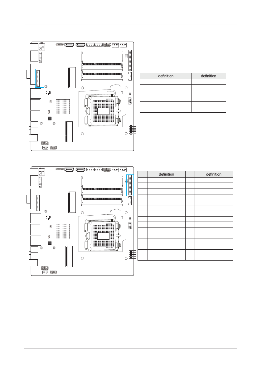
3.5 FUSB1 and USB20_3 extended interfaces
through USB bracket, FUSB1 can provide two USB
ports, USB20_3 can pick out a USB port. USB bracket
for optional accessories, you can contact the local
dealer.
pin pin
1 VCC 2 VCC
3 DATA- 4 DATA-
5 DATA+ 6 DATA+
7 GND 8 GND
9 NC 10 GND
FUSB1
USB20_3
pin pin
1 VCC 2 USBP10N
3 USBP10P 4 GND
5 NC
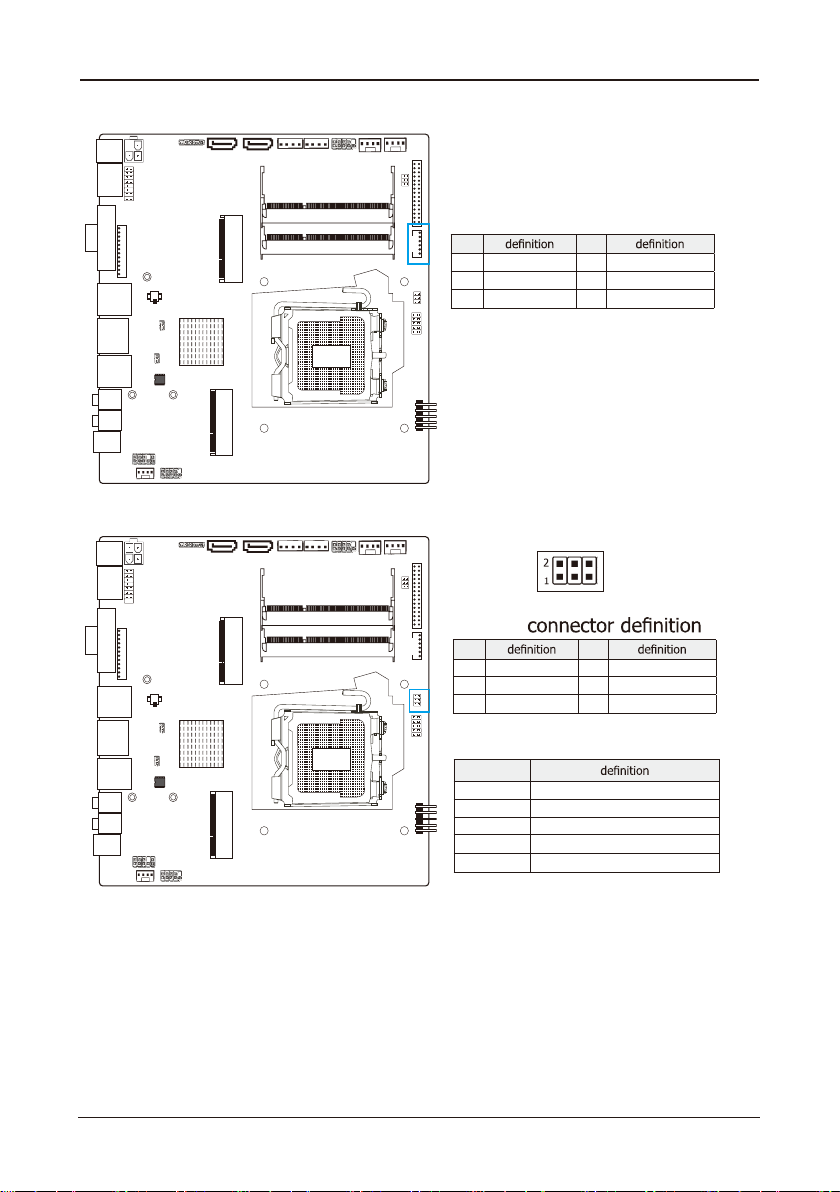
3.6 HDD_PWR1/2(SATA POWER Interface) and JDCIN(DC POWER Interface)
pin pin
1 12V 2 GND
3 GND 4 5V
By the power socket,the power supply
can provide power that is enough and
stable for all the components on the
mainboard.
Before inserting into the power
socket,please make be sure that the
power of power supply has been turned
off ,and allthe components and devices
protection design,After confirming that
the direction is right ,you can insert.

- 15 -
ECB-H81C11S User's Manual
PJ 1
HDMI
VGA1
USB1
LAN1
USB2
F_MIC
SPDIF1
FAUDIO
SPEAKERS JCOM1
BIOS
CLR_CMOS
JME
MPCIE
MSATA
BAT
OC_AGV N
OC_IMDH N
JDCIN USB20_3SATA1 S ATA2 HDD_PWR 2 HDD_PWR1 FPANELCPU_FAN SYS_FAN
VL OC_SD N
EVNI TR RE 11
LJ DV S
IPGJ O
FUSB1
F_OUT
DIMM2
DIMM1
L RWP_DC
PJ 1
HDMI
VGA1
USB1
LAN1
USB2
F_MIC
SPDIF1
FAUDIO
SPEAKERS JCOM1
BIOS
CLR_CMOS
JME
MPCIE
MSATA
BAT
OC_AGV N
OC_IMDH N
JDCIN USB20_3SATA1 S ATA2 HDD_PWR 2 HDD_PWR1 FPANELCPU_FAN SYS_FAN
VL OC_SD N
EVNI TR RE 11
LJ DV S
IPGJ O
FUSB1
F_OUT
DIMM2
DIMM1
L RWP_DC
3.8 HDMI_CON Connector
pin pin
1 HDMIC_TX2_DP 2 HDMIC_SCL
3 HDMIC_TX2_DN 4 HDMIC_SDA
5 HDMIC_TX1_DP 6 GND
7 HDMIC_TX1_DN 8 DPC_HPD_CN
9 HDMIC_TX0_DP 10 DAC_5V
11 HDMIC_TX0_DN 12 GND
13 HDMIC_CLK_DP 14 GND
15 HDMIC_CLK_DN 16 GND
3.7 FAN Power Connectors
Note:These fan connectors are not jumpers. DO NOT
place jumper caps on these connectors.
- 16 -
ECB-H81C11S User's Manual
PJ 1
HDMI
VGA1
USB1
LAN1
USB2
F_MIC
SPDIF1
FAUDIO
SPEAKERS JCOM1
BIOS
CLR_CMOS
JME
MPCIE
MSATA
BAT
OC_AGV N
OC_IMDH N
JDCIN USB20_3SATA1 S ATA2 HDD_PWR 2 HDD_PWR1 FPANELCPU_FAN SYS_FAN
VL OC_SD N
EVNI TR RE 11
LJ DV S
IPGJ O
FUSB1
F_OUT
DIMM2
DIMM1
L RWP_DC
PJ 1
HDMI
VGA1
USB1
LAN1
USB2
F_MIC
SPDIF1
FAUDIO
SPEAKERS JCOM1
BIOS
CLR_CMOS
JME
MPCIE
MSATA
BAT
OC_AGV N
OC_IMDH N
JDCIN USB20_3SATA1 S ATA2 HDD_PWR 2 HDD_PWR1 FPANELCPU_FAN SYS_FAN
VL OC_SD N
EVNI TR RE 11
LJ DV S
IPGJ O
FUSB1
F_OUT
DIMM2
DIMM1
L RWP_DC
3.9 VGA_CON Connector
pin pin
1 GND 2 5V_VSYNC
3 5V_HSYNC 4 GND
5 VGA_R 6 GND
7 VGA_G 8 GND
9 VGA_B 10 GND
11 5V_DDCA_DATA 12 5V_DDCA_CLK
3.10 LVDS_CON Connector(Display Port)
pin pin
1 LCDVDD 2 LCDVDD
3 LCDVDD 4 GND
5 GND 6 GND
7 LVDSA_DATA0N 8 LVDSA_DATA0P
9 LVDSA_DATA1N 10 LVDSA_DATA1P
11 LVDSA_DATA2N 12 LVDSA_DATA2P
13 GND 14 GND
15 LVDSA_CLKN 16 LVDSA_CLKP
17 LVDSA_DATA3N 18 LVDSA_DATA3P
19 LVDSB_TX0N 20 LVDSB_TX0P
21 LVDSB_TX1N 22 LVDSB_TX1P
23 LVDSB_TX2N 24 LVDSB_TX2P
25 GND 26 GND
27 LVDSB_CLKN 28 LVDSB_CLKP
29 LVDSB_TX3N 30 LVDSB_TX3P
- 17 -
ECB-H81C11S User's Manual
PJ 1
HDMI
VGA1
USB1
LAN1
USB2
F_MIC
SPDIF1
FAUDIO
SPEAKERS JCOM1
BIOS
CLR_CMOS
JME
MPCIE
MSATA
BAT
OC_AGV N
OC_IMDH N
JDCIN USB20_3SATA1 S ATA2 HDD_PWR 2 HDD_PWR1 FPANELCPU_FAN SYS_FAN
VL OC_SD N
EVNI TR RE 11
LJ DV S
IPGJ O
FUSB1
F_OUT
DIMM2
DIMM1
L RWP_DC
PJ 1
HDMI
VGA1
USB1
LAN1
USB2
F_MIC
SPDIF1
FAUDIO
SPEAKERS JCOM1
BIOS
CLR_CMOS
JME
MPCIE
MSATA
BAT
OC_AGV N
OC_IMDH N
JDCIN USB20_3SATA1 S ATA2 HDD_PWR 2 HDD_PWR1 FPANELCPU_FAN SYS_FAN
VL OC_SD N
EVNI TR RE 11
LJ DV S
IPGJ O
FUSB1
F_OUT
DIMM2
DIMM1
L RWP_DC
3.11 INVERTER1 Connector
pin pin
1 IVT_VCC 2 IVT_VCC
3 PNON 4 BKLT_PWM1
5 GND 6 GND
3.12 JLVDS Connector
pin pin
1 GND 2 GND
3 RLV_CFG 4 RLV_LNK
5 GND 6 NC
pin
NC 6 BIT
1-3 8 BIT JEIDA
3-5 8 BIT VESA
2-4 NC DUAL LINK LVDS
2-4 CLOSE SINGLE LINK LVDS
JLVDS jumper setting
JLVDS

- 18 -
ECB-H81C11S User's Manual
PJ 1
HDMI
VGA1
USB1
LAN1
USB2
F_MIC
SPDIF1
FAUDIO
SPEAKERS JCOM1
BIOS
CLR_CMOS
JME
MPCIE
MSATA
BAT
OC_AGV N
OC_IMDH N
JDCIN USB20_3SATA1 S ATA2 HDD_PWR 2 HDD_PWR1 FPANELCPU_FAN SYS_FAN
VL OC_SD N
EVNI TR RE 11
LJ DV S
IPGJ O
FUSB1
F_OUT
DIMM2
DIMM1
L RWP_DC
PJ 1
HDMI
VGA1
USB1
LAN1
USB2
F_MIC
SPDIF1
FAUDIO
SPEAKERS JCOM1
BIOS
CLR_CMOS
JME
MPCIE
MSATA
BAT
OC_AGV N
OC_IMDH N
JDCIN USB20_3SATA1 S ATA2 HDD_PWR 2 HDD_PWR1 FPANELCPU_FAN SYS_FAN
VL OC_SD N
EVNI TR RE 11
LJ DV S
IPGJ O
FUSB1
F_OUT
DIMM2
DIMM1
L RWP_DC
3.13 JGPIO Connector
pin pin
1 GPI_1+ 2 GPI_1+
3 GPI_2+ 4 GPI_2+
5 GPI_3+ 6 GPI_3+
7 GPI_4+ 8 GPI_4+
9 GND 10 GND
3.14 Front Panel Audio Connector
Pin No. Header
1 PORT1L Microphone_Left Microphone
2 AGND Ground Ground
3 PORT1R Microphone_Right MIC Power
4 PRESENCE# -ACZ_DET N/A
5 PORT2R Line2_Right Line out (R)
6 SENSE1_RETURN AuD_R_Return N/A
7 SENSE_SEND FAUDIO_JD N/A
8 No Pin N/A N/A
9 PORT2L Line2_Left Line Out(L)
10 SENSE2_RETURN AuD_L_Return N/A
- 19 -
ECB-H81C11S User's Manual
PJ 1
HDMI
VGA1
USB1
LAN1
USB2
F_MIC
SPDIF1
FAUDIO
SPEAKERS JCOM1
BIOS
CLR_CMOS
JME
MPCIE
MSATA
BAT
OC_AGV N
OC_IMDH N
JDCIN USB20_3SATA1 S ATA2 HDD_PWR 2 HDD_PWR1 FPANELCPU_FAN SYS_FAN
VL OC_SD N
EVNI TR RE 11
LJ DV S
IPGJ O
FUSB1
F_OUT
DIMM2
DIMM1
L RWP_DC
PJ 1
HDMI
VGA1
USB1
LAN1
USB2
F_MIC
SPDIF1
FAUDIO
SPEAKERS JCOM1
BIOS
CLR_CMOS
JME
MPCIE
MSATA
BAT
OC_AGV N
OC_IMDH N
JDCIN USB20_3SATA1 S ATA2 HDD_PWR 2 HDD_PWR1 FPANELCPU_FAN SYS_FAN
VL OC_SD N
EVNI TR RE 11
LJ DV S
IPGJ O
FUSB1
F_OUT
DIMM2
DIMM1
L RWP_DC
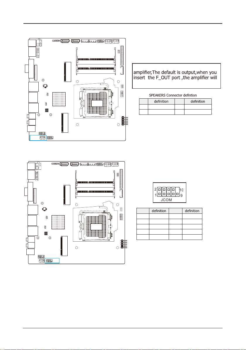
3.15 SPEAKERS Connector
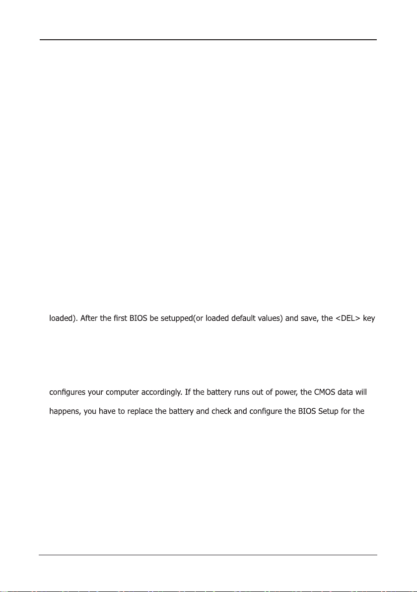
3.16 JCOM1 Connector
pin pin
1 DCD 2 RXD
3 TXD 4 DTR
5 GND 6 DSR
7 RTS 8 CTS
9 RI
The SPEAKERS is audio output for 3W
be not output.
pin pin
1 Right + 2 Right -
3 Left- 4 Left+
- 20 -
ECB-H81C11S User's Manual
Chapter 4 BIOS Setup Utility
BIOS stands for Basic Input and Output System. It was once called ROM BIOS when it was
stored in a Read-Only Memory (ROM) chip. Now manufacturers would like to store BIOS in
EEPROM which means Electrically Erasable Programmable Memory. BIOS used in this series
of mainboard is stored in EEPROM, and is the first program to run when you turn on your
computer.
BIOS performs the following functions:
1. Initializing and testing hardware in your computer (a process called "POST", for Power On
Self Test).
2. Loading and running your operating system.
3. Helping your operating system and application programs manage your PC hardware by
means of a set of routines called BIOS Run-Time Service.
4.1 About BIOS Setup
BIOS Setup is an interactive BIOS program that you need to run when:
1. Changing the hardware of your system. (For example: installing a new Hard Disk etc.)
2. Modifying the behavior of your computer. (For example: changing the system time or date,
or turning special features on or off etc.)
3. Enhancing your computer's behavior. (For example: speeding up performance by turning
on shadowing or cache)
4.2 To Run BIOS Setup
First access BIOS setup menu by pressing <F1> key after “POST” is complete (before OS is
will be pressed if you will enter BIOS setup menu.
4.3 About CMOS
CMOS is the memory maintained by a battery. CMOS is used to store the BIOS settings you
have selected in BIOS Setup. CMOS also maintains the internal clock. Every time you turn
on your computer, the BIOS Looks into CMOS for the settings you have selected and
be lost and POST will issue a “CMOS invalid” or “CMOS checksum invalid” message. If this
new start.
4.4 The POST (Power On Self Test)
POST is an acronym for Power On Self Test. This program will test all things the BIOS does
before the operating system is started. Each of POST routines is assigned a POST code, a
unique number which is sent to I/O port 080h before the routine is executed.
This manual suits for next models
1
Table of contents
Other Strontech Motherboard manuals


