Struers Exotom 100 User manual

Exotom-100
Instruction Manual
Manual No.: 15047001
Date of Release 30.07.2003


Exotom-100
Instruction Manual
Table of Contents Page
User’s Guide ..............................................................1
Reference Guide.......................................................19
Quick Reference Card .............................................48
A
lways state Serial No and Voltage/frequency if you have technical questions or when ordering spare parts. You will
find the Serial No. and Voltage on the type plate of the machine itself. We may also need the Date and Article No of
the manual. This information is found on the front cover.
The following restrictions should be observed, as violation of the restrictions may cause cancellation of Struers legal
obligations:
Instruction Manuals: Struers Instruction Manual may only be used in connection with Struers equipment covered by
the Instruction Manual.
Service Manuals: Struers Service Manual may only be used by a trained technician authorised by Struers. The
Service Manual may only be used in connection with Struers equipment covered by the Service Manual.
Struers assumes no responsibility for errors in the manual text/illustrations. The information in this manual is subject
to changes without notice. The manual may mention accessories or parts not included in the present version of the
equipment.
The contents of this manual is the property of Struers. Reproduction of any part of this manual without the written
permission of Struers is not allowed.
A
ll rights reserved. © Struers 2003.
Struers A/S
Pederstrupvej 84
DK-2750 Ballerup
Denmark
Telephone +45 44 600 800
Fax +45 44 600 801


Exotom-100
Instruction Manual
Exotom-100
Safety Precaution Sheet
To be read carefully
before use
1. The operator(s) should be fully instructed in the use of the machine and its cut-
off wheels according the Instruction Manual and the instructions on the cut-off
wheels.
2. Use the supplied Allen key to remove the two red transport screws at the rear of
the machine. Do not attempt to open the protection guard before the screws
have been removed.
3. The machine must be placed on a safe and stable support. All safety functions
of the machine must be in working order. The machine must be levelled by
means of the adjustable legs provided.
4. The unit must be installed in compliance with local safety regulations.
5. Prior to lifting the unit by the built-in truck lifting point, ensure that the boom is
properly secured with the locking pins provided. Before transport, secure the
cutting arm with the locking system provided.
6. To achieve maximum safety and lifetime of the machine, use only original
Struers consumables.
7. Use only intact cut-off wheels. The cut-off wheels must be approved for a
spindle speed of min. 1950 rpm / 42 m/s. Do not use sawblades.
8. Observe the current safety regulations for handling, mixing, filling, emptying and
disposal of the additive for cooling fluid.
9. The workpiece must be securely clamped in the quick-clamping device or the
like. Large or sharp workpieces must be handled in a safe way.
10. Struers recommend the use of an exhaust system as the cutting materials may
emit harmful gasses or dust. See the instructions of the cut-off wheel.
11. The machine emits only moderate noise. However, the cutting process itself
may emit noise, depending on the nature of the workpiece. In such cases, use
of hearing protection is recommended.
12. The machine must be disconnected from the mains prior to any service.
13. Ensure that the cut-off wheel is secured before working on or around the cutting
table.
14. Do not put hands through the rubber curtain during operation of the machine.

Exotom-100
Instruction Manual
15. Protruding workpieces should be shielded or marked.
16. Use of working gloves is recommended as workpieces may be both very hot
and produce sharp edges.
17. If any unusual noise is heard when the protection hood is operated, refrain from
further use of the machine, and contact Struers service technician.
The equipment is designed for use with consumables supplied by Struers. If subjected to misuse, improper
installation, alteration, neglect, accident or improper repair, Struers will accept no responsibility for
damage(s) to the user or the equipment.
Dismantling of any part of the equipment, during service or repair, should always be performed by a qualified
technician (electromechanical, electronic, mechanical, pneumatic, etc.).

Exotom-100
Instruction Manual
1
User’s Guide
Table of Contents Page
1.Getting Started
Checking the Contents of Packing................................................... 3
Recirculation Cooling Unit........................................................ 3
Unpacking and Placing Exotom-100................................................ 3
Mounting the Control Panel............................................................. 4
Getting Acquainted with Exotom-100 ............................................. 5
Side view, left.............................................................................6
Side view, right.......................................................................... 6
Cooling unit compartment ........................................................ 7
Power Supply .................................................................................... 8
Mounting the Cut-off wheel ............................................................. 8
Direction of the Cut-off Wheel ..................................................8
Connection to an External Exhaust System ................................... 8
Setting Up the Recirculation Cooling Unit ..................................... 9
Direct Water Supply for the Cooling Unit....................................... 9
2.Operation
Using the Controls.......................................................................... 10
Control Panel of Exotom-100 .................................................. 10
Control Panel Functions................................................................. 11
Display Types.................................................................................. 11
Setting the Language ..................................................................... 12
Reading the Cutting Display..........................................................13
Changing Cutting Mode and Cutting Parameters........................ 14
Changing Cutting Mode .......................................................... 14
Changing Cutting Parameters................................................ 14
Reading the Motor Information.............................................. 14
Sleep Mode............................................................................... 14
Changing the Cut-off Wheel........................................................... 15
Clamping the Workpiece ................................................................15
Positioning the Cut-off Wheel ........................................................ 15
QuickPosition.................................................................................. 16
Cutting Parameters ........................................................................ 16
Feed ................................................................................................. 16
Force ................................................................................................ 16
Stop.................................................................................................. 16
AutoStop................................................................................... 16

Exotom-100
Instruction Manual
2
Setting the Cutting Parameters .................................................... 17
Cutting on Exotom-100................................................................... 17
Starting the Cutting................................................................ 17
Fast advance ............................................................................ 17
Stopping the Cutting (Manual Stop) ...................................... 17
Re-starting cutting .................................................................. 17
Direct Cut........................................................................................ 18
ExciCut............................................................................................ 18
AxioCut (option).............................................................................. 18
Additional cooling ........................................................................... 18

Exotom-100
Instruction Manual
3
1.Getting Started
The packing box contains the following items:
1 Exotom-100
1 Control Panel for Exotom-100
1 Allen key (5 mm) for mounting Control Panel
3 Screws (5 mm)
1 Fork spanner (30 mm) for cut-off wheel
1 Spanner (comb. 12/17 mm) for adjustment of the
Control Panel
1 Drain hose, 2 m
1 Fitting for drain hose
2 Cabinet doors
1 Set of Instruction Manuals
1 Recirculation cooling unit
1 Trolley for cooling unit
Unscrew the nuts from the four transport bolts fixing the machine to
the pallet.
Lift the machine from the pallet by means of a forklift truck from the
front, and place in a suitable location.
Remove the safety-springs from the front crossbar, and remove bar.
Use the supplied Allen key to remove the two red transport
screws at the rear of the machine. Do not attempt to open the
protection hood before the screws have been removed.
Take out the loose parts (trolley, tank, drain hose etc.).
Mount the cabinet doors.
Turn the adjustable feet so that the machine stands firmly and is
level.
Checking the Contents of
Packing
Recirculation Cooling Unit
Unpacking and Placing
Exotom-100
NB!
Please remove the transportation
support before use.
Exotom-100
Instruction Manual
4
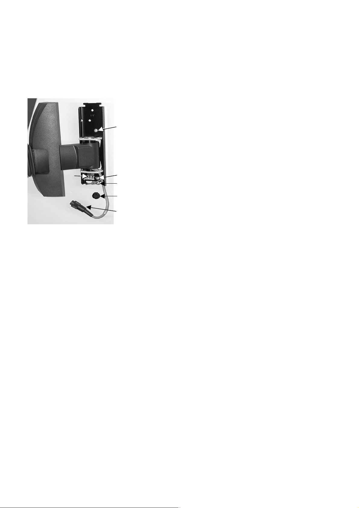
Unpack the Control Panel and mount on right side of unit using the
two 5 mm screws and Allen key supplied (use holes and as
indicated on drawing).
Mount the earth wire below the mounting plate using the
third 5 mm screw .
Press cover towards cabinet wall until it snaps onto the mounting
plate.
Connect Control Panel plug to socket .
The position of the Control Panel is controlled by a friction
mounting. After mounting the control panel it is possible to
adjust the mobility of the Control Panel this way:
Adjust the main joint with the nut using the combined
12/17 mm spanner supplied.
The joint just behind the Control Panel may be adjusted too,
using the same spanner.
Mounting the Control Panel
Exotom-100
Instruction Manual
5
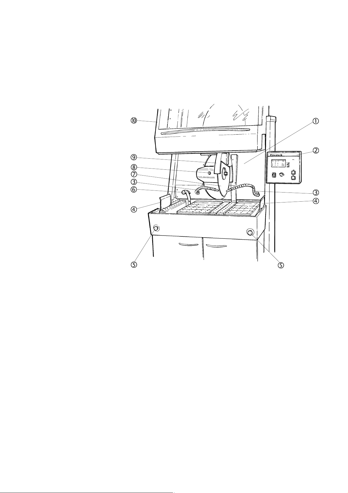
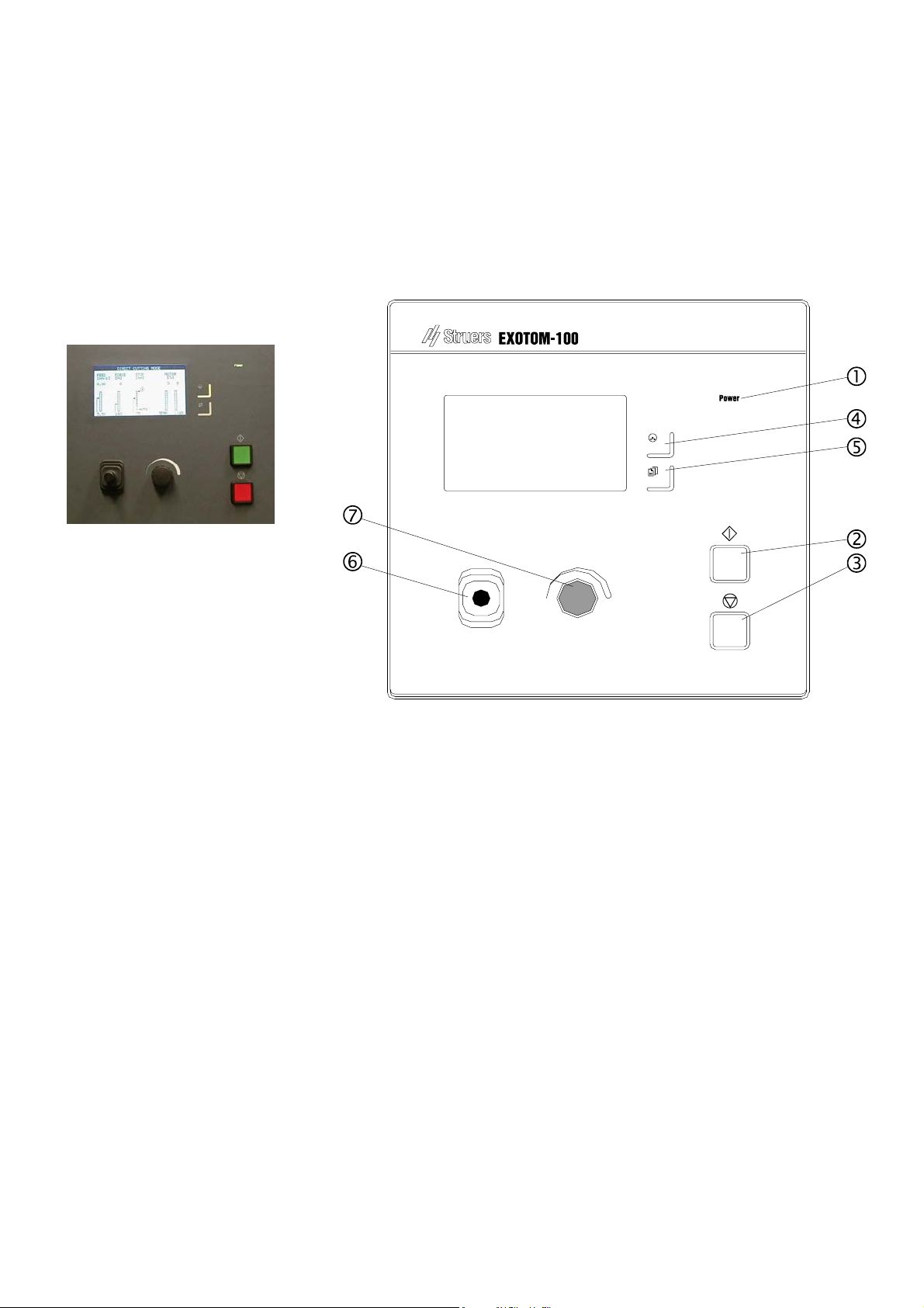
Take a moment to familiarise yourself with the location and
names of the Exotom-100 components.
Cutting chamber
Control Panel
Flexible water jets
Protection guards
Emergency stops
Flushing hose with flush nozzle
Cut-off wheel
Spindle lock button
Guard for cut-off wheel
Protection hood
Getting Acquainted with
Exotom-100

Exotom-100
Instruction Manual
6
Exhaust flange
Water inlet
Water outlet
Name Plate
Type plate
Main Switch
Electrical connection box
Connection for electrical cable for power supply
Connection for external warning light
Fuse socket for external warning light
1Connection for Control Panel
Side view, left
Side view, right
Exotom-100
Instruction Manual
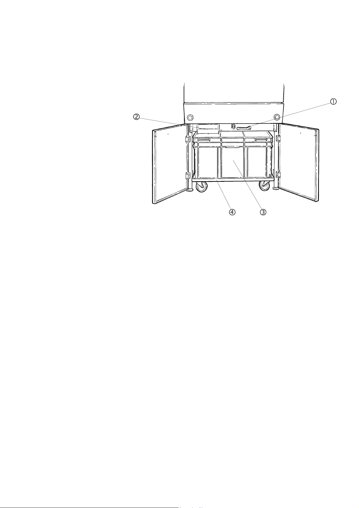
7
Cooling unit drain pump on/off
Filter drawer
Recirculation cooling unit
Trolley for cooling unit
Cooling unit compartment
Exotom-100
Instruction Manual
8
Before connecting the machine, check that the mains voltage is
correct by referring to the type plate.
Open the electric connection box and connect a 4-lead cable in the
following way:
PE: earth
L1: phase
L2: phase
L3: phase
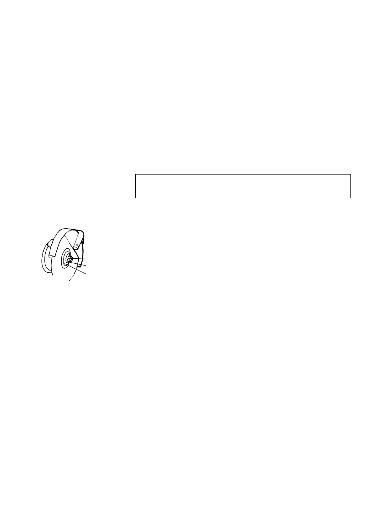
Press the knob for the spindle lock on the left-hand side of the cut-off
wheel, while turning the cut-off wheel until the spindle lock clicks.
Remove the nut with a fork spanner (30mm).
Remove the flange and the cut-off wheel.
Mount the new cut-off wheel with a cardboard flange on each side.
Mount the flanges and nut. Tighten carefully.
To check that the cut-off wheel rotates in the direction indicated
on the wheel-guard, do the following:
Close the protection hood.
Turn Main Switch to On.
Press START s.
Check the rotational direction of the wheel.
Press STOP o.
If the direction of rotation is incorrect, turn mains off and switch
two of the phases.
Struers recommends the use of an exhaust system as workpieces
may emit harmful gases when cut. The unit is prepared for
connection to an exhaust system via an 80 mm fitting on the left
hand side of the cabinet.
Recommended capacity for exhaust system: 350m3/h at 0mm
water gauge.
Power Supply
IMPORTANT
Check that the mains voltage corresponds to the voltage stated on the type
plate on the side of the machine.
Mounting the Cut-off wheel
Direction of the Cut-off Wheel
Connection to an External
Exhaust System
ee
Nut
Flange
Washer

Exotom-100
Instruction Manual
9
Check that the nylon sieve in the filter drawer is properly placed and
close the drawer.
Mount the drain hose on the back of the machine.
Place the recirculation cooling unit in the compartment.
Fill the cooling unit with 150 l of water (5-10 cm from the upper
edge).
Use additive enclosed with the machine and add to cooling water as
specified on the bottle label and stir.
Exotom-100 may be directly connected to the water mains.
Connect the water inlet fitting (½” internal, ¾” external thread).
Open the external water supply.
Fill the cooling unit with 150 l of water (5-10 cm from the upper
edge).
Shut off the water.
Add additive in the quantity stated on the bottle label and stir.
Setting Up the
Recirculation Cooling Unit
IMPORTANT
The cooling unit must be positioned inside the compartment as indicated by
the arrows on the edge of the cooling unit.
Direct Water Supply for the
Cooling Unit
IMPORTANT
When the cooling unit is pushed into the compartment, care should be
taken that the flushing hose is not trapped behind it.
To counter this, pull the flushing hose all the way out of its holder, then
replace. The flushing hose, should then rest inside the cooling unit.
Exotom-100
Instruction Manual
10
2.Operation
Using the Controls
Control Panel of Exotom-100
Exotom-100
Instruction Manual
11
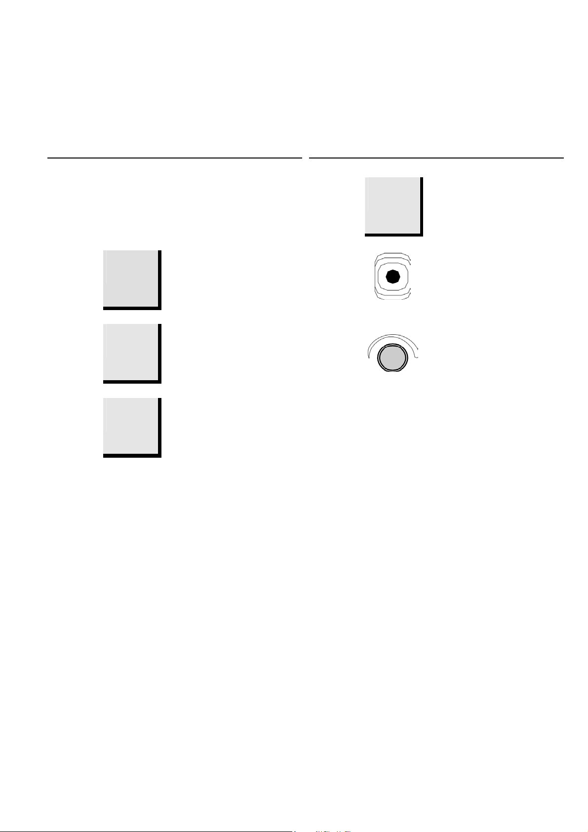
Name Key Function Name Key Function
1
POWER
Power
Lights when the Main Switch has
been turned to ON. 5
MENU
m Push button to toggle between
Cutting menu (daily use) and
Configuration menu (basic settings).
2
START
s Starts the machine and recirculation
unit. 6
JOYSTICK
Move up- or downwards to position
cut-off wheel.
3
STOP
o Stops the machine and recirculation
unit. 7
MULTI-
FUNCTION
KNOB
Push knob to select function. Turn
knob to adjust settings.
4
CUTTING
MODE
U Push button to select desired cutting
mode: Direct cutting, ExciCut,
AxioCut/Step, AxioCut/Sweep.
The Cutting Display will be shown on the Control Panel when
turning Exotom-100 on. This display is for everyday use.
By pressing the MENU mbutton once, the CONFIGURATION
menu will appear on the display. This menu will normally only be
accessed during installation.
Control Panel Functions
Display Types

Exotom-100
Instruction Manual
12
m Press MENU mbutton once to select
CONFIGURATION Menu.
D
Turn knob to toggle between parameters in the
CONFIGURATION Menu.
D
Push knob to select LANGUAGE. A pop-up menu
appears.
D
From the pop-up menu, select your preferred language
by pushing the knob.
D
Press MENU mbutton to move from
CONFIGURATION Menu to Cutting Display.
Setting the Language
Exotom-100
Instruction Manual
13
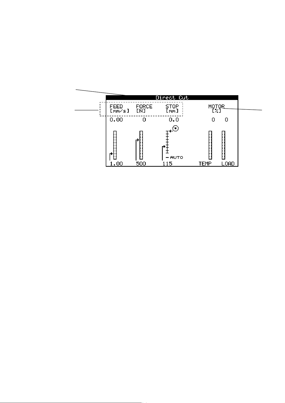
The Cutting Display offers three types of information:
Cutting Mode
Cutting Parameters, and
Motor Information
A Cutting Mode.
B Cutting Parameters.
CMotor Information.
The top bar displays the selected Cutting Mode:
Direct Cutting, ExciCut, AxioCut/Step or AxioCut/Sweep
(AxioCut/Step and -/Sweep are optional).
The large window on the Cutting Display, displays information
about the Cutting Parameters (FEED, FORCE, STOP) as well as
Motor information (TEMP, LOAD).
The Cutting Parameters (FEED, FORCE and STOP) can be set
both prior to and during cutting. The set value is displayed below
the column. Actual value is displayed above the bar graph.
The Motor Information columns TEMP and LOAD, inform about
the condition of the motor during cutting. Read-out in relative
value (%).
Reading the Cutting Display
Cutting Mode
Cutting Parameters and Motor
Information
B
A
C

Exotom-100
Instruction Manual
14
Toggle between the four Cutting Modes, by pressing the
CUTTING MODE button. The selected mode, Direct Cutting,
ExciCut, AxioCut/Step or AxioCut/Sweep, appears on the top bar
of the Cutting Display.
Toggle between the three Cutting Parameters by pushing the
knob. The highlighted Cutting Parameter is selected.
Actual values of the Cutting Parameters FEED, FORCE and
STOP are displayed on top of the columns (A).
The actual position of the cut-off wheel (relative its starting
position) is displayed graphically by the small icon to the right
of the STOP column.
Turn the knob to change the setting of the selected Cutting
Parameter. The arrow on the left of the column will move to
reflect the new setting (B).
By moving the pointer of the STOP column below the column,
AUTO mode is selected.
The highlighted area of the bar graphs TEMP and LOAD, shows
the status of the cutting motor:
TEMP. Temperature indicator of the cutting motor.
LOAD. Load indicator of the cutting motor.
To increase the lifetime of the display, the backlight is
automatically switched off if Exotom-100 has not been used for 15
min. Push any key on the Control Panel to re-activate the
backlight.
Changing Cutting Mode and
Cutting Parameters
Changing Cutting Mode
Changing Cutting Parameters
Push knob to select Cutting
Parameter.
Turn knob to adjust setting.
Reading the Motor Information
Sleep Mode
B
A
Table of contents
Languages:
Other Struers Saw manuals


Popular Saw manuals by other brands

DeWalt
DeWalt DW304 instruction manual

GÜDE
GÜDE GTK 800 Translation of original operating instructions

General International
General International BT8005 Setup and operation manual

SSP
SSP MLC141 instruction manual

Craftsman
Craftsman 137.212520 Operator's manual

Festool
Festool TSC 55 REB Original operating manual


Makita
Makita HS012G instruction manual

Festool
Festool TS 55 FEBQ Original instructions

Makita
Makita 2414DB instruction manual

Meister
Meister BHKS 1200 LB LASER Translation of the original operating instructions

Black & Decker
Black & Decker CS1024 instruction manual

Hafco
Hafco MetalMaster CS-315D instruction manual