Table of Contents
1 SAFETY REGULATIONS
........................
3
1.1 General Safety Advice
.......................
3
1.2 Blade Guard Safety
...........................
3
1.3 Emergencies
.....................................
3
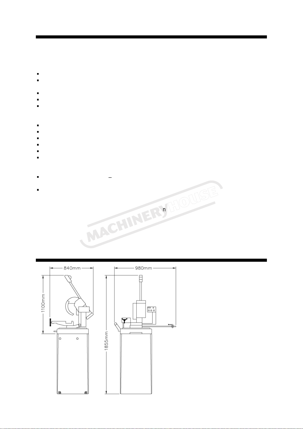
2 MACHINE DIMENSIONS
.........................
3
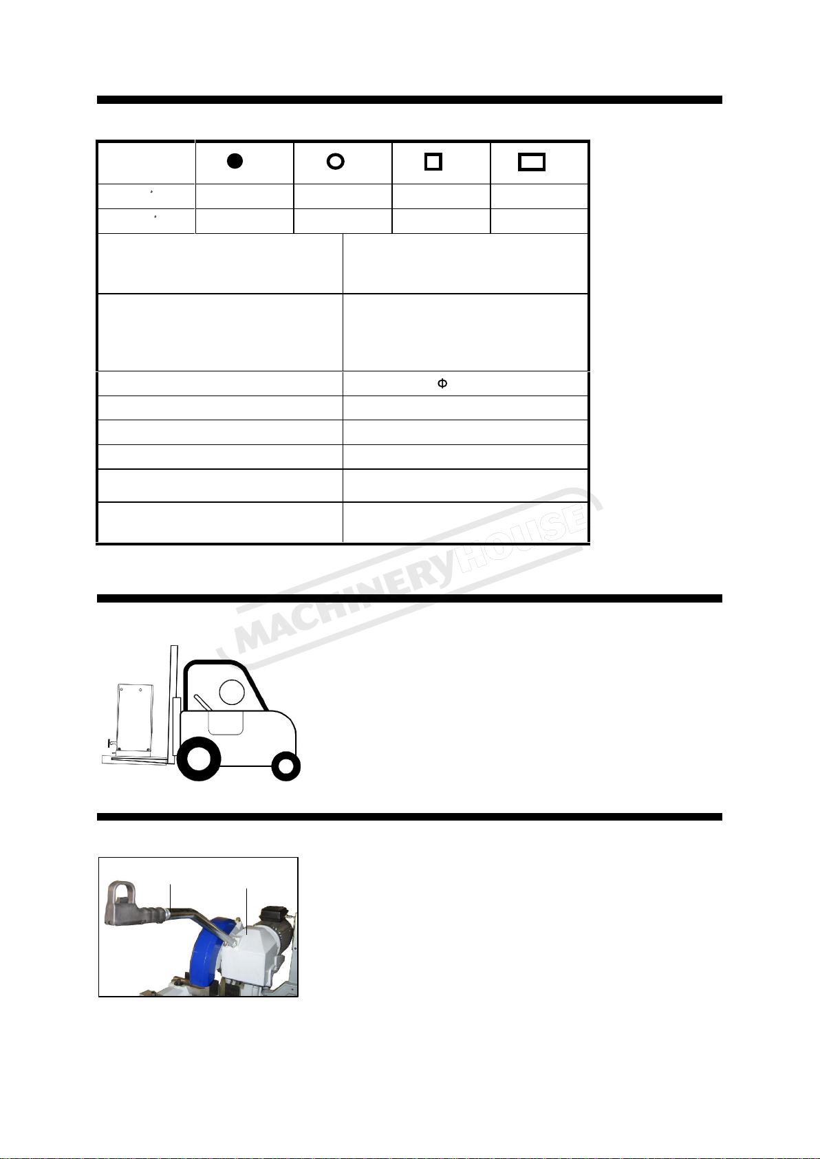
3 TECHNICAL CHARACTERISTICS
.........
4
3.1
General Characteristics
.....................
4
4 TRANSPORTING THE MACHINE
...........
4
5 GETTING TO KNOW YOUR MACHINE
..
4
5.
1 Disk Head Assembly
.........................
4
5.2 Machine Base
....................................
5
5.3 Vice
...................................................
5
5.4 Support
Roller ...................................
5
5.5 Stand
.................................................
5
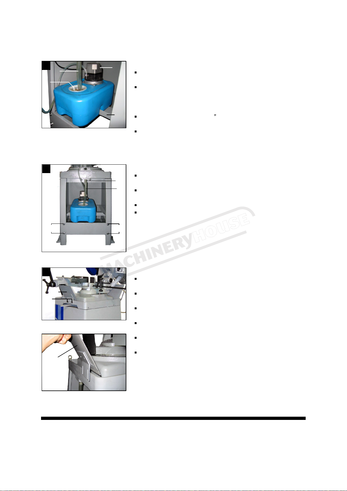
5.6 Coolant Pump
....................................
5
6 GETTING STARTED
...............................
6
6.1 Minimum Requirements for Housing
the Machine
.............................................
6
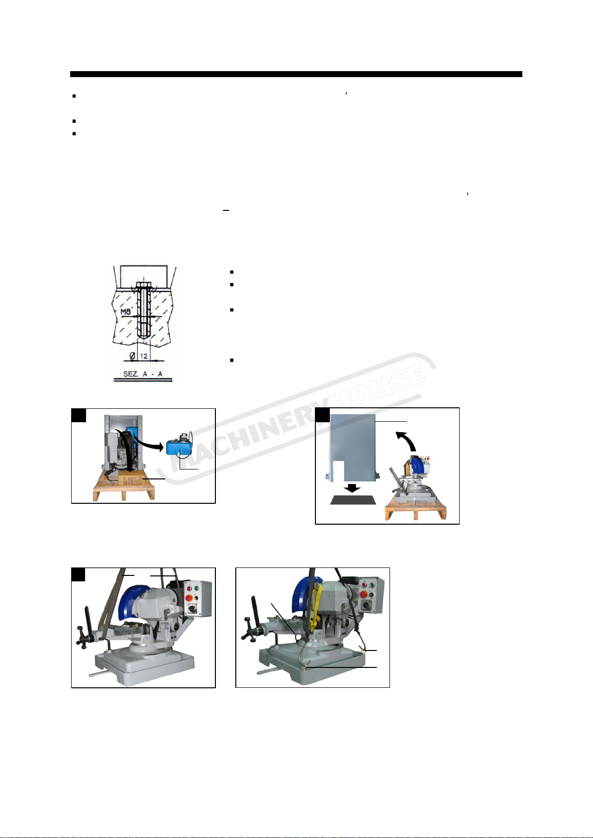
6.2 Anchoring the Machine
......................
6
6.3 Assembly and Setup
.........................
6
7 RECOMMENDATIONS AND ADVICE
....
9
7.1 General Advise Before Using the
Machine
.................................................10
7.2 Operator Position
............................10
7.3 Deactivating the Machine
................10
7.4 Dismantling......................................10
8 ADJUSTING THE MACHINE
.................11
8.1 Disk Head........................................11
8.2 Adjusting the Mitering Lock Lever
...11
8.3 Changing the Disk...........................11
8.4 Cleaning and Accessing the Coolant
System
..................................................11
9 THE OPERATION CYCLE
.....................12
9.1 Miter Angle
......................................12
9.2 Vise Operation
................................
.
12
9.3 Loading the Work
-
piece
..................12
9.4 Setting Cutting Length
.....................13
9.5 Operation Cycle
...............................13
10 ROUTINE AND SPECIAL
MAINTENANCE
........................................14
10.1 Daily Maintenance.........................14
10.2 Weekly Maintenance
.....................14
10.3 Monthly Maintenance
....................14
10.4 Six
-
Monthly Maintenance
..............14
10.5 Oils
for Lubricating Coolant
...........14
10.6 Oil Disposal
...................................14
10.7 Special Maintenance
.....................14
11 MATERIAL CLASSIFICATION AND
CHOICE OF TOOL
...................................15
11.1 Disk Structure
................................15
11.2 Choosing the Saw Blade
...............15
11.3 Type of Disks ................................16
11.4 Choosing the Tooth Pitch
..............17
11.5 Cutting and Advance Speed
.........17
11.6 Running in the Disk
.......................18
11.7 Cutting Speed Chart
......................18
11.8 Recommended Cutting Parameters
..............................................................19
12 EXPLOSION DRAW AND PART LISTS
..................................................................20
12.1 Explosion draw A
..........................20
12.2
Part List A
......................................21
12.3
Part List B
......................................22
12.4
Explosion draw B
..........................23
12.5
WIRING DIAGRAM AND PARTS
LIST
.......................................................24
13 TROUBLESHOOTION
.........................26
13.1 Blade and cut diagnosis................26
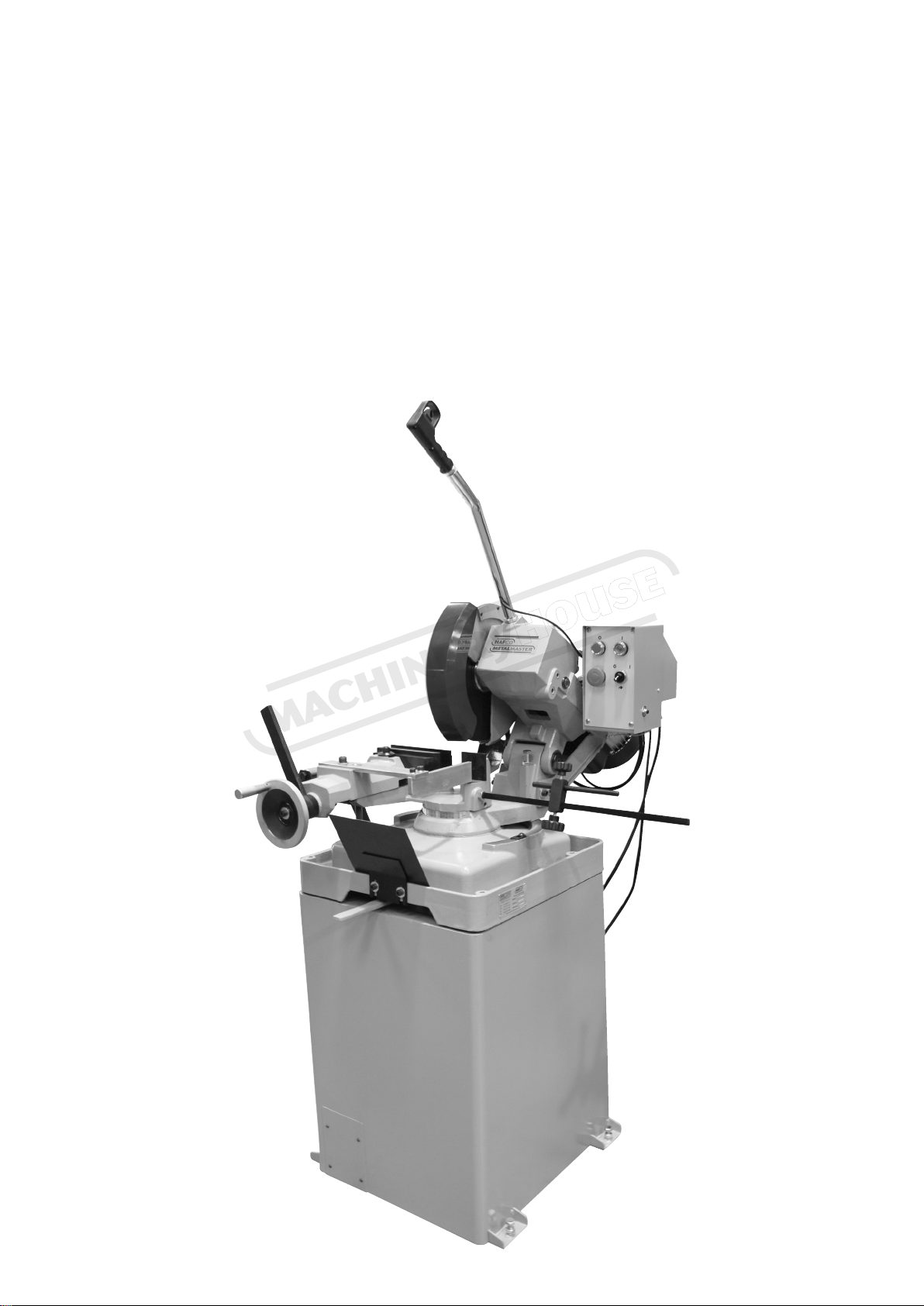
Instruction Manual for CS-315D (S828)