STRYDE BIKE User manual

BIKE Manual

2
Table Of Contents
Safety Information 3
Operation Instructions 5
Bike Specifications 6
Display Specifications 7
Stryde Pre-Assem ly 8
Setting Up Your Bike 15
Adjusting The Saddle 17
Adjusting The Handle ar 18
Torq Kno And Emergency Brake 19
Getting Started 20
Class Screen 22
General Maintenance 23
Limited Home Warranty 26

3
Safety Information
Read this manual carefully before using the Stryde bike.
ollow all operating and maintenance instructions. Please
keep this manual for future reference. Improper use or
maintenance can result in injury and void the warranty
terms.
WARNING!
Please train all the users of the ike to follow these safety
instructions. DO:
1. Use this equipment only for its intended use as
descri ed in this manual. Do not attempt to ride this
ike at high pedal speeds until you have ridden the ike
for some time and are comforta le riding at slower
pedal speeds.
2. Stop y reducing the pedaling frequency in a controlled
manner or press the emergency rake to a stop efore
dismounting the ike.
3. Serious injury or death may occur from over-training.
Consult a medical doctor or qualified fitness instructor
to determine an exercise program appropriate for your
level of fitness.
4. Do not attempt to turn the pedal cranks y hand. Do not
touch any driving mechanism while it is in motion as
possi le injury could occur.
5. In a home setting, keep children away from the ike
when it is not in use. Keep children and pets away from
the unit while it is in use.
6. Never drop or insert any o ject into any opening of the
ike.
7. Only use the ike on a sta le, level floor.
8. Follow instructions for safe use of the equipment
including proper seat position, handle ar position, and
use of foot positioning system of pedals. Do not attempt
to pull up handle ar post and seat post over the ‘MAX.’
graduation.
9. For safe operation, allow for at least 2 feet (60cm) of
free space to either side of the unit and 2 feet (60cm) of
free space to the rear of the unit.

4
10. Before eginning this or any exercise program, consult a
physician. This is especially important for persons over
the age of 35 or persons with pre-existing health
conditions.
11. The ike should not e used y persons exceeding 350
l s in weight.
12. Close supervision is necessary when this exercise
equipment is used y, on, or near children, invalids, or
disa led persons.
Regularly examine the ike for damage and wear.
Inopera le components should e replaced immediately or
the equipment should not e used until it is repaired.
Failure to follow all guidelines may compromise the
effectiveness of the exercise experience, expose yourself
(and possi ly others) to injury, and reduce the longevity of
the equipment.

5
Operation Instructions
Warning - As the owner of this exercise equipment, you
should insist that all users follow the same guidelines: you
should make this manual available to all users.
1. O tain a complete physical examination from your
medical doctor and enlist a health/ fitness
professional’s aid in developing an exercise program
suita le for your current health status.
2. When working out for the first time, start out slowly for
a minimum of five minutes.
3. After your muscles are warmed up, gradually increase
the pedaling speed and/or resistance.
4. The speed and duration of your exercise program
should always e su ject to how you feel. Never permit
peer pressure to exceed your personal judgment while
exercising.
5. This exercise equipment is not intended for use y
persons with reduced physical, sensory or mental
capa ilities, or lack of experience and knowledge.
6. Overweight or severely de-conditioned individuals
should e particularly cautious when using the
equipment for the first time. Even though such
individuals may not have histories of serious physical
pro lems, they may perceive the exercise to e far less
intense than it really is, resulting in the possi ility of
overexertion or injury.
7. Proper installation and regular maintenance are
required to ensure user’s safety.
8. Maintenance is the sole responsi ility of the owner.
6
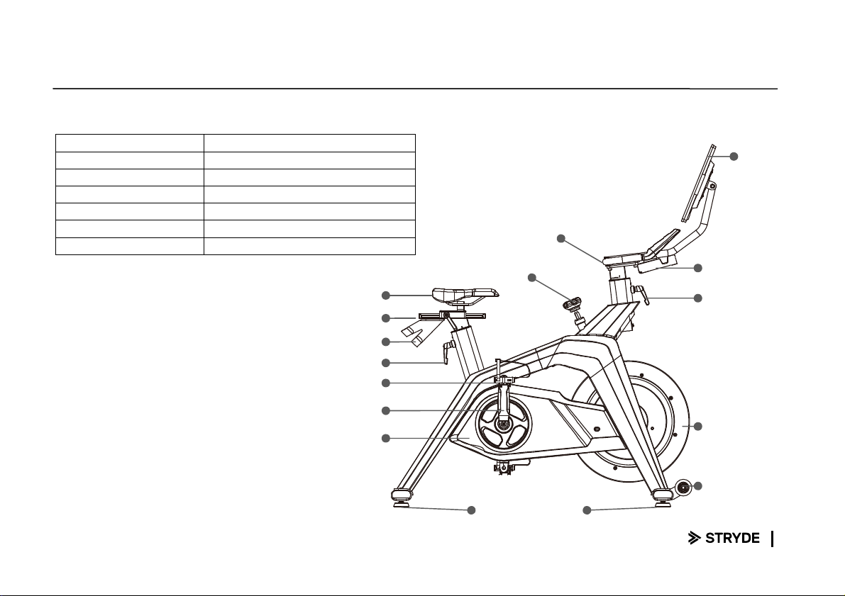
Bike Specifications
Tech Specs And Requirements
Footprint 24” x 49.6” (61cm x 126 cm)
Bike Weight 124.6 l (56.5 kg)
Max Saddle Height 42.5” (108 cm)
Max Handle ar Height 46” (117 cm)
User Height Range 5’ 1” to 6’ 5” (155 cm - 200 cm)
Max User Weight 350 l (160 kg)
Pedals SPD pedals with toe cages
Seat
Seat Adj. Locking
Dum ell Bracket
Seat Adj. Locking
Pedal
Crank Arm
Shrouds
Handle Bar
Brake Tension Kno Bottle Holder
Handle ar Adj.
Locking Lever
Flywheel
Transportation
Wheel
Screen
Adjustment Foot
Leveler

7
Display Specifications
Display
21.5” 1080P HD Touchscreen
Android 8.1 Operating System
16 GB Flash Storage
ANT+
™
and Bluetooth ® 5.0
MT8167A Processor

8
Stryde Pre-Assem ly
Use the following procedures to unpack and assem le
your Bike.
1. Using a razor knife (Box Cutter) cut the outside,
ottom, edge of ox. Lift Box over the unit and
unpack.
2. Carefully remove all parts from carton and inspect
for any damage or missing parts. If damaged parts
are found, or parts are missing, contact us
immediately.
3. Locate the hardware package. Each part in the
hardware package is la eled with a num er. Remove
the tools first. Remove the hardware for each step as
needed to avoid confusion.
CAUTION: Damage to the bike during assembly is not
covered as part of the limited arranty. Take care not
to drop or lean the bike on its side.
Carefully stand the bike up in the normal upright
position on a stable surface so it ill not tip over during
assembly.
Protect the environment by not disposing of this
product ith household aste. Check your local
authority or approved aste center for recycling advice
and facilities.

9
Stryde Pre-Assem ly CONTINUED
Tools Needed:
#106. 14/15m/m Wrench (1pc)
#108. Phillips Head Screw Driver (1pc)
#107. M6 L Allen Wrench (1pc)
#109. M4 L Allen Wrench (1pc)
10
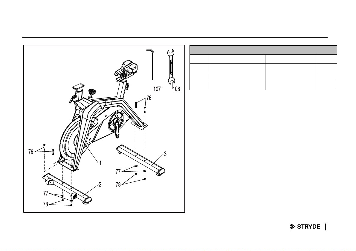
Stryde Step One
HARDWARE OR STEP 1
PART
TYPE DESCRIPTION QTY
76 Button Head Socket Bolt
3/8" × 2-1/4" 4
77 Flat Washer Ø10 × Ø 25 × 1.5T 4
78 Nylon Nut 3/8" × 7T 4
1. Align the screw holes of the main frame (1) and the front
sta ilizer tu e (2). Insert two 3/8"×2-1/4"_Button Head Socket
Bolt (76) through the holes and tighten them with two sets of
Ø10×Ø25×1.5T_Flat Washer (77) and 3/8"×7T_Nylon Nut (78)
y using a 14/15m/m_Wrench (106) and a M6 Allen Wrench
(107).
2. Align the screw holes of the main frame (1) and the rear
sta ilizer tu e (3). Insert two 3/8"×2-1/4"_Button Head Socket
Bolt (76) through the holes and tighten them with two sets of
Ø10×Ø25×1.5T_Flat Washer (77) and 3/8"×7T_Nylon Nut (78)
y using a 14/15m/m_Wrench (106) and a M6 Allen Wrench
(107).

11
Stryde Step Two
HARDWARE OR STEP 2
PART
TYPE DESCRIPTION QTY
101 Button Head Socket Bolt
M6 × 18L 2
102 Flat Washer Ø 6.5 × Ø 25 × 1.5T 2
1. Align the screw holes of the dum ell holder (29) and seat
racket. Tighten with two sets of Ø6.5×Ø25×1.5T_Flat Washer
(102) and M6×18L_Button Head Socket Bolt (101) y using a
M4 Allen Wrench (109).
12
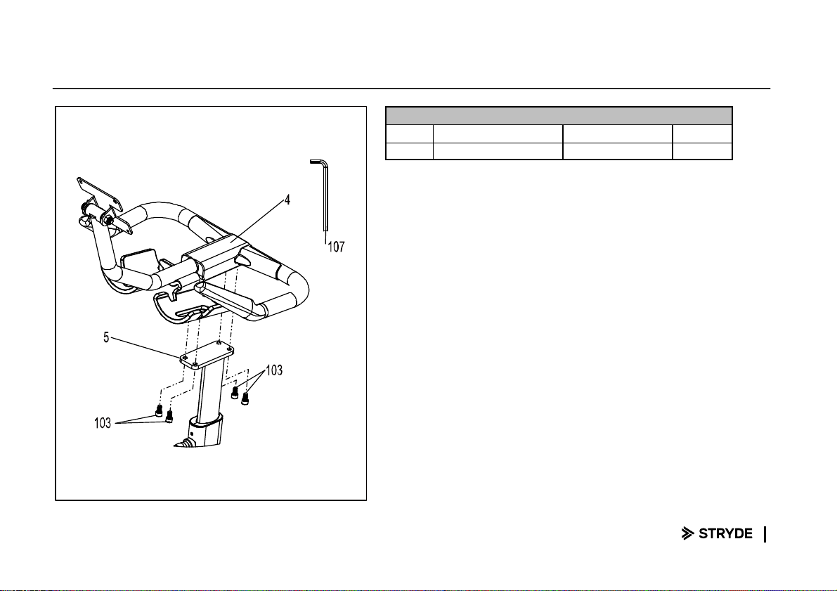
Stryde Step Three
HARDWARE OR STEP 3
PART
TYPE DESCRIPTION QTY
103 Socket Head Cap Bolt M8 × 15L 4
1. Pull the handle ar post (5) up with some space for assem ly.
2. Align the screw holes of the handle ar set (4) and handle ar
post racket. Tighten with four M8×15L_Socket Head Cap Bolt
(103) y using a M6 Allen Wrench (107).
13
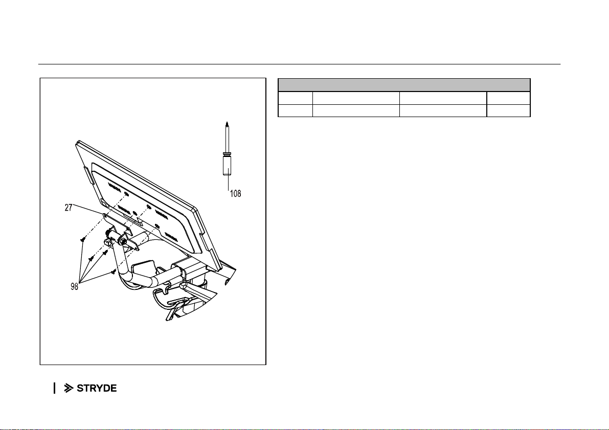
Stryde Step Four
HARDWARE OR STEP 5
PART
TYPE DESCRIPTION QTY
98 Phillips Head Screw M4 × 12L 4
1. Align the screw holes of the screen rack (27) and the ta let.
Tighten with four M4×12m/m_Phillips Head Screw (98) y
using a Screw driver (108).
14
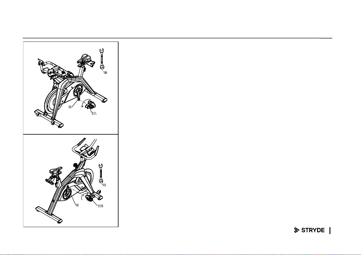
Stryde Step Five
1. Tighten the Left pedal (37) onto the Left crank arm (36) y
using a 14/15m/m_Wrench (106).
2. Tighten the Right pedal (37) onto the Right crank arm (35) y
using a 14/15m/m_Wrench (106).

15
Setting Up Your Bike
24"(60cm)
24"(60cm)
24"(60cm)
24"(60cm)
Positioning The Bike
The ike should e on a level, flat, and
secure surface near an AC power
outlet. Keep a minimum safe distance
of 24” (60 cm) etween the ike and
any o structions.
Injury Warning
To prevent injury, always adjust the
saddle and handle ars to your personal
requirements and tighten all
adjustment levers efore taking your
first ride. Protruding levers and kno s
can interfere with your movements.
Note: It’s recommended that the
assem ly should e done y two
people.

16
Setting Up Your Bike
Moving The Bike
Two wheels are located on the front floor
mount for easily relocating the ike.
Grip the ack floor mount and tilt the ike
forward (1)
While avoiding uneven surfaces, roll the ike
to its new location
If the ike rocks after eing set down, turn
each leveling foot until it rests firmly on the
floor (2)
Equipment Warning
Do not unscrew the leveling feet more then
1⁄2”.
Before moving your ike, adjust your
handle ar and saddle settings to their lowest
levels.
1
2

17
Adjusting The Saddle
With your hips level in the saddle, your knees
should e slightly ent when the pedal is
closest to the floor.
When oth pedals are parallel to the floor, your
forward kneecap should e directly a ove the
center of the pedal.
Height
Turn the adjustment lever counterclockwise to
loosen (1)
Adjust the saddle to a desired position (2)
Turn the lever clockwise to tighten
Depth
Turn the rear adjustment lever counterclockwise to
loosen (3)
Slide the saddle forward or ackward (4)
Turn the lever clockwise to tighten
Injury Warning
To avoid hyper-extending your knees, make sure
that your legs are not completely straight.
Do not adjust saddle height eyond the stop mark
on the seatpost.
2
1
3
4

18
Adjusting The Handle ar
When gripping the handle ar, your
arms should
e slightly ent, and the handle ar should e at
the same height (or slightly higher) than the
top of the saddle.
Height
Turn the adjustment lever counterclockwise to
loosen (1)
Adjust the handle ar to a desired position (2)
Turn the lever clockwise to tighten
1
2
19
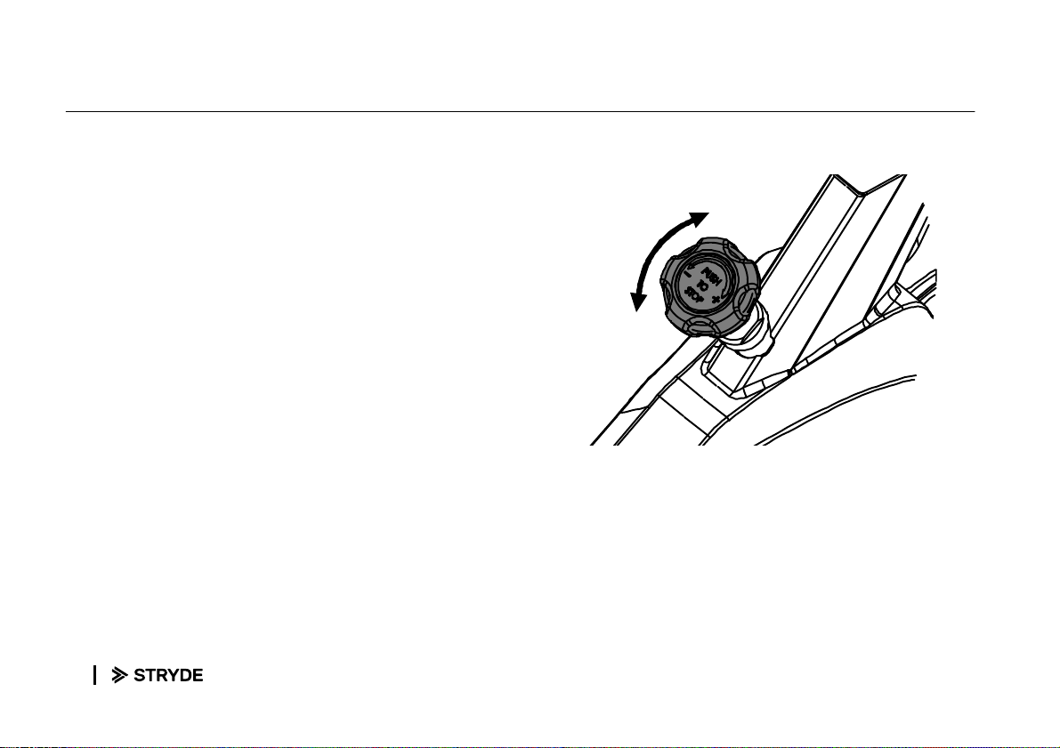
Torq Knob And Emergency Brake
Turn the Torq kno to adjust
the
resistance
level, or press it as an emergency rake.
Turn clockwise to increase resistance
Turn counterclockwise to decrease resistance
Push down to stop the pedals and wheel from
moving
Equipment Warning
Increase the resistance to maximum when the ike
is not in use to prevent injuries from moving pedals.
The pedals and wheel will continue to move
together until the wheel stops. The emergency
rake shall e released after the wheel comes to a
complete stop and pressure is removed from the
pedals.
20
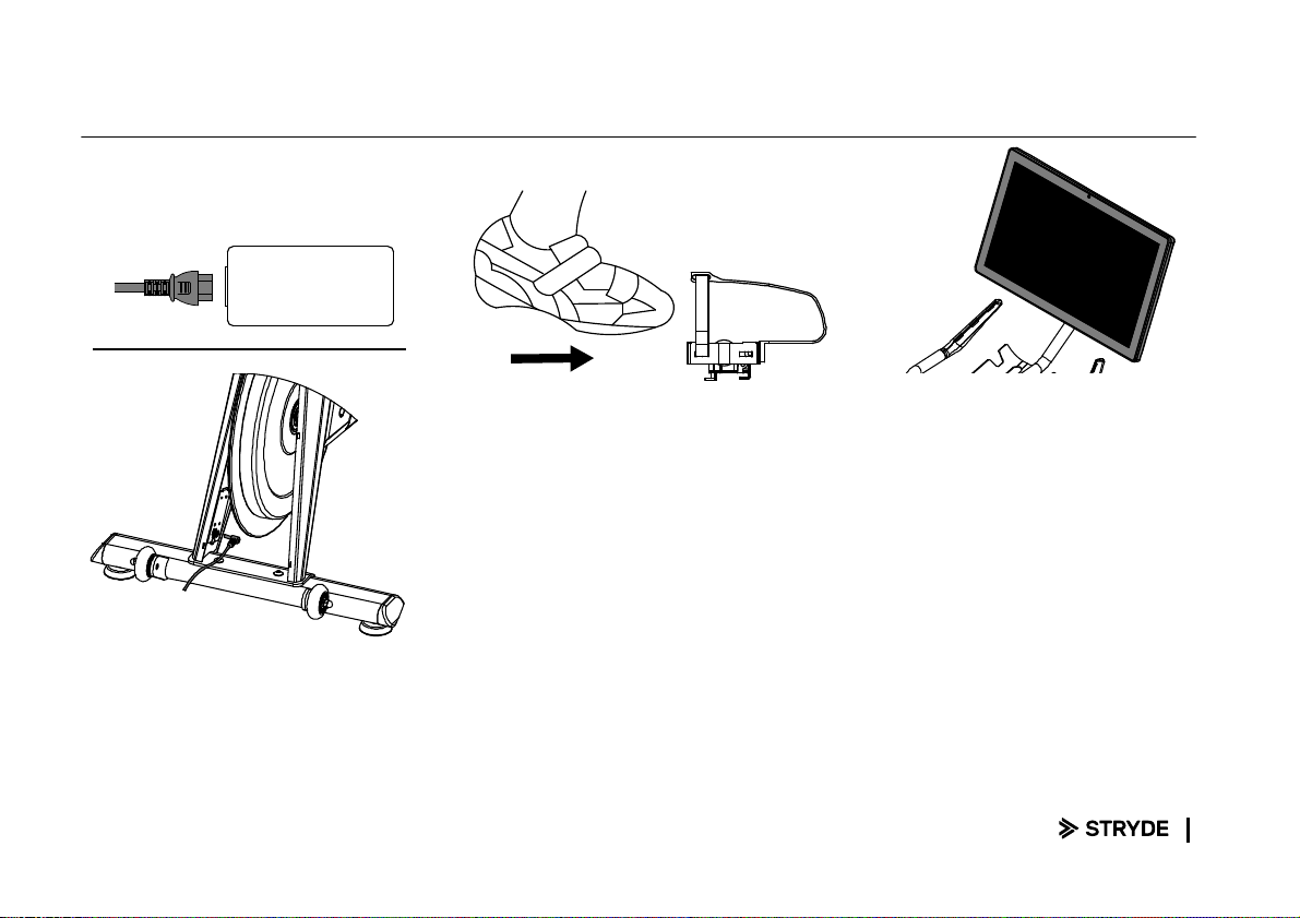
Getting Started
Plugging In
Plug the power cord into the
adapter on the ottom of the ike,
then plug the other end into an
outlet. Plug the two ca les from
the ike into the ta let as shown
on page 7
Clipping In
If you are using cycling shoes with
SPD clips, find the U-shaped side of
the pedal, then slide the all of
your foot down while dropping
your heel until you hear a click.
Clipping Out
With your hand on the Torq Kno ,
swing your heel away from the
ike.
Turning on your tablet
Your ta let will start automatically when you
plug in the ike and connect the ta let. Your
ta let will go to sleep after several minutes of
inactivity. If the display is asleep, swipe up on
the screen to wake it up.
Table of contents
Popular Exercise Bike manuals by other brands


Sunny Health & Fitness
Sunny Health & Fitness SF-B121021 user manual

Monark
Monark 827E instruction manual

Stamina
Stamina 1310 owner's manual

American Fitness
American Fitness SPR-BK1072A owner's manual
 Service manual")
Cateye
Cateye CS-1000 (CYCLO SIMULATOR) Service manual

BH FITNESS
BH FITNESS H9158H Instructions for assembly and use