STS M-750LG User manual

Surface to Surface Inc. ®
Operators Manual
** M-750LG **
USE IN CONJUNCTION WITH OEM MANUALS (ENCLOSED)
Unit Serial No. _______________
Engine
Robin Engine Serial No. ______________
Gorman-Rupp Pump
GR-84B2 – Serial No. ________________
Links relating to this Manual
www.stsmixers.com
www.robinamerica.com
www.grpumps.com
STS-046 Rev. 09/29/22 www.stsmixers.com
Dealer

2
TABLE OF
CONTENTS
PAGE
STS Inc Warranty………………………………………………………….. 5
Safety Statements………………………………………………...………… 6-9
Safety Markings……………………………………………………………. 10
Main Working Components (Photo)……………………………………… 11
Introduction to the M-750……………….………………………………. 12
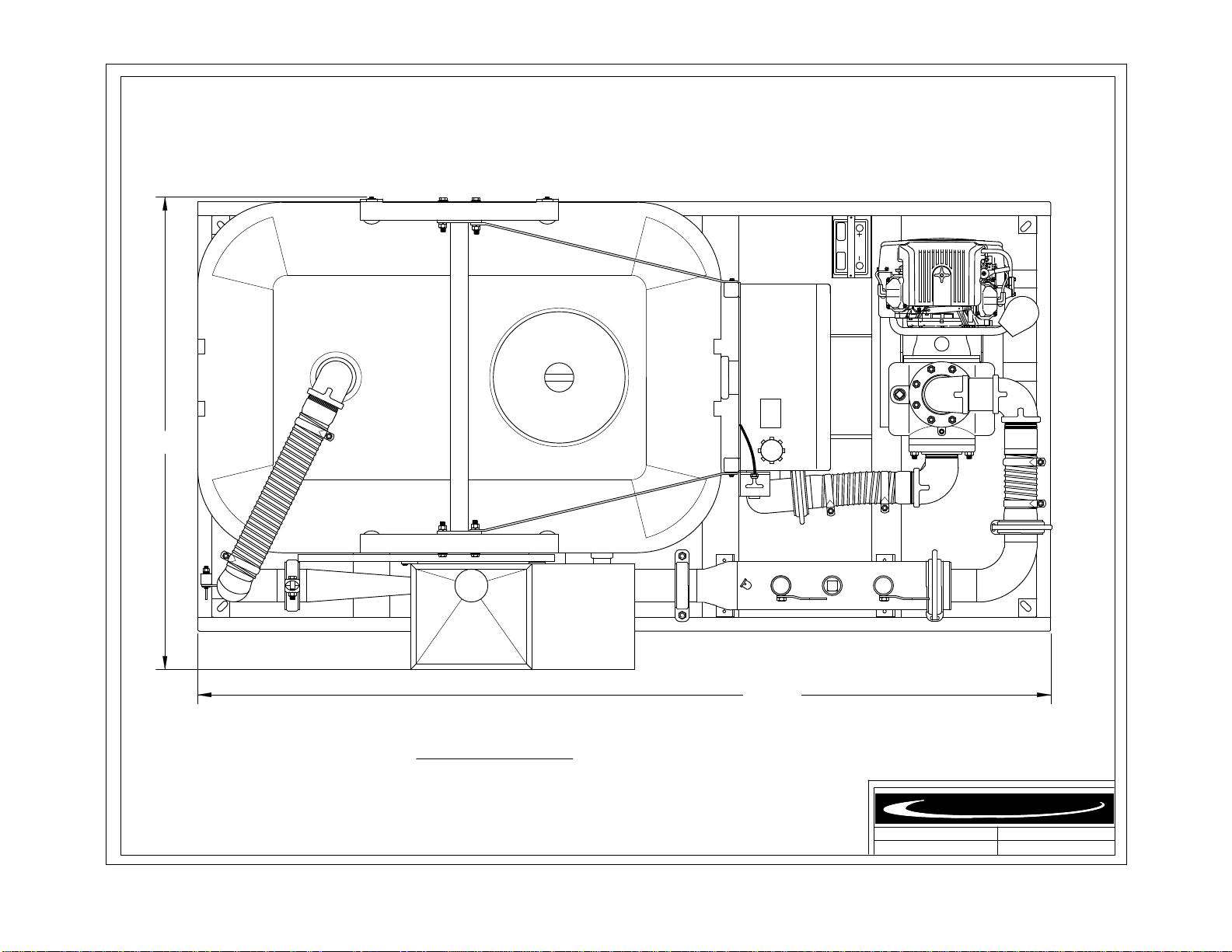
M-750LG Foot Print (top view)……………………………………………… 13
M-750LG General Data Sheet………………………………………………. 14
Identifying Your Machine & Components………………………………. 15
SECTION II (Description, Care and Maintenance)
Polyethylene Plastic Reservoir Tank…………………….…………… 17-18
Gasoline powered centrifugal pump.…….…………….……. 19-22
Filter shear system……………………………………………………. 23-24
Venturi mixing tee……………………………..………..……………. 25
Wash wand……………………………………………………...……. 26
Dry hopper with table & hopper valve…………………………..…… 27
Internal tank jet gun…………………………………...……………… 28
SECTION III (Set-up and installation of unit in Detail)
Permanent mounting of unit…………………………...…………….. 30
Portable use of unit…………………….…………………….………. 30

3
TABLE OF
CONTENTS
PAGE
SECTION IV (Operating the M-750 Unit.)
Site set-up and pre-check…………………………………………….. 32
Starting the engine and pump………………………....……………… 33
Typical mixing operation……………………….……………………. 34
Typical transfer / off-loading operation……………………………… 35
Shutdown, cleanup & storage
Warm weather…………………………………….…………. 36
Cold/ freezing weather………………………………….…… 37
Prolonged periods of storage………………………………… 38
**Optional self-loading feature……………………………...………… 39
SECTION V (Trouble shooting)
Trouble Shooting the M-750…………….…………………..……… 41-42
SECTION VI (Periodic Maintenance & Repair Information)
Maintenance Schedule…………………….….………………….…... 44
Centrifugal Trash Pump Seal Replacement………………………..… 45
Bolt torque Specifications…………………………………….……... 46
Notes…………………………………………………….…………… 47

4
TABLE OF
CONTENTS
PAGE
SECTION VII (OEM Repair Information)
GR Centrifugal Pump Owner’s Manual……………………..………… 49-60
Engine Manufacture Customer Help (web-site)………………………. 61
Gruvloc® Pipe Couplings……………………….………………..…… 62-64
SECTION VIII (Parts Manual)
M-750LG PARTS MANUAL…………………….……………….……. 66-69

5
Limited Warranty
United States and Canada
Surface to Surface Inc. or it’s subsidiary which last sold the product, warrants new products sold by it for use in the
United States and Canada to be, at the time of manufacture, free from defects in workmanship and materials. This
warranty covers for a period of Twelve (12) Months of operation from the date of delivery for initial use, whichever
comes first.
Exclusions and Additional Limitations
1. This warranty relates to the condition of the product at the time of manufacture and does not cover parts or
service as a result of:
(a) Normal wear and tear or required maintenance including, without limitation, adjustments or replacement of
components subject to wear and tear, such as belts, hoses, seals and/or packing, fuses, bulbs,
switches and ignition parts.
(b) Abuse including, without limitation, neglect, improper operation, misapplication, overloading, accident or
alterations not approved by Surface to Surface Inc.
(c) Lack of maintenance, including, without limitation, failure to inspect and maintain, improper repair, use of
“unapproved parts”, cracked engine heads and blocks unless caused by the failure of
an internally lubricated part or repair of engine valves, rings or guides.
2. The Company’s warranty does not apply to purchased components manufactured by others where separate
warranty is made by the manufacture of such components and will be applied as interpreted by
the supplier.
3. All claims under his warranty shall be submitted in writing by the distributor to the Company, which will be the
sole judge in determining the merits of the claim.
4. The company shall have the right to have all products or parts claimed to be defective returned to it and the
cost of shipping such items shall be borne by the distributor.
……………………………………………………………………………………
Warranty Registration Card
In order to help us provide complete service for our product, please complete this card and return it.
If not returned, all requests for warranty will be denied.
Print Name: …………………………………………………………………….….
Address: …………………………………………………………………………...
City: ……………………State/Province………………Zip/PC…………………...
Model No. ………………………….. Serial No. …………………………………
Date of Purchase ………………………… Dealer ………………………………..
Return to: Surface to Surface Inc.
5150 Forest Rd. RR#3
Watford, Ontario, Canada
N0M 2S0
01/14/08
6
M-750LG
SAFETY STATEMENTS
Your personal safety and the safe operation of this unit are the concern of Surface to Surface Inc, and by
reading and understanding this manual and understanding the safety statements, you will decrease the risk of
personal and equipment damage.
Safety statements are listed here and throughout this manual to draw your attention to potential hazards that
may be encountered while operating this piece of equipment. While reading this manual, you will notice that
certain safety statements will relate directly to the operation, or maintenance of that particular part of the unit and
should be followed carefully. Decals on the unit also follow the same format as the warnings in this manual, and
therefore should be kept in good repair to alert the operator and others of the potential hazard.
The engine / motor manual also contains hazard warnings which pertain to the engine / motor and should
also be followed.
This safety alert symbol appears with most safety statements.
It means attention, become alert, your safety is involved!
Please read and abide by the message that follows the safety alert symbol.
DANGER
WARNING CAUTION
CAUTION
Caution "without the safety alert symbol"
indicates an potentially hazardous
situtation that can cause damage to the,
machine, personal property and / or the
environment or cause the machine to
operate improperly.
Danger (the word "DANGER" is in white
letters with a red rectangle behind it)
indicates an imminently hazardous
situation, which, if not avoided, will
result in death or serious injury.
Danger is limited to the most extreme
situations.
Warning (the word "WARNING" is in black
letters with an orange rectangle behind it)
indicates an potentially hazardous
situation which, if not avoided, could
result in death or serious injury.
Caution (the word "CAUTION" is in black
letters with a yellow rectangle behind it)
indicates an potentially hazardous
situation which, if not avoided, may
result in minor or moderate injury.
7
M-750LG
SAFETY STATEMENTS
The following caution statements have been drawn from the instructions in this manual. They
have been assembled here for ready reference.
DANGER
IN AN EMERGENCY
DANGER
NEVER ATTEMPT REPAIRS
OR DISASSEMBLY
without shutting off the engine / motor
and disconnecting the power source.
Serious personal injury will result.
WARNING
NEVER USE BODY PARTS,
OR FOREIGN OBJECTS
in an attempt to unplug or clean the
hopper valve or mixing tee.
Serious personal injury or
damage will result.
WARNING
Serious personal injury will result.
DO NOT REMOVE OR MODIFY
SAFETY COVERS OR GUARDS.
WARNING
while the unit is in operation.
Serious personal injury will result.
NEVER ATTEMPT TO REMOVE
OR CLEAN THE FILTER SHEAR
CAUTION
DO NOT POSITION
ANY PART OF YOUR BODY
over the hopper, valve,
or mixing tee while cleaning.
CAUTION
WHEN THE UNIT
IS IN OPERATION,
the fluid in the piping may reach
pressures up to 50 p.s.i.
When the engine is idling, the system is
still pumping fluid under pressure.
CAUTION
NEVER OPERATE THE MIXING
unit with the tank lid open.
If viewing is necessary, open
only the small inspection
vent cap in the center of the lid.
rotate the key switch to
the STOP position
to halt engine, pump, and fluid flow

8
M-750LG
SAFETY STATEMENTS continued
The following caution statements have been drawn from the instructions in this manual. They
have been assembled here for ready reference.
CAUTION
TRAPPED FLUID MAY BE PRESENT
and will spill out when piping, hoses,
pump or filter shear are removed.
CAUTION
AVOID ALLOWING FOREIGN MATERIAL
into the Venturi Mixing Tee thru the
Hopper, by keeping the valve closed
when not in use.
CAUTION
NEVER LEAVE LIQUID IN THE
PUMP CASING, PIPING, OR HOSES
during freezing weather conditions,
as damage will result.
Follow instruction for winterizing.
CAUTION
BEFORE STARTING THE ENGINE,
BE SURE THE PUMP IS PRIMED!
CAUTION
CAUTION
CARE MUST BE TAKEN WHEN
INSTALLING THE COUPLER GASKETS.
If the gaskets are not properly lubricated
and installed, a leak may develop.
CAUTION
BEFORE STARTING OR RESTARTING
the engine and centrifugal pump, make
sure any valves installed on the pump
suction inlet line are open, and the
fluid level in the tank is above
the suction line.
IMPROPER INSTALLATION OF THE
MECHANICAL or GREASE SEAL
will result in leakage and possible
damage to the seal. All maintenance,
operating and repair of this unit, must be
done per the instructions in the operators
manual for safety and reliability.
CAUTION
WHEN TRANSFERRING FLUID
to the drill rig, fluid pressure may
reach or exceed 50 p.s.i.
CHECK the drill rig manufacturers
specifications regarding maximum inlet
pressures allowed for their pump.
Check the pump by slowly & carefully
opening the plug located on the top
of the centrifugal pump discharge elbow.
A visual inspection can be made if the fluid
escapes around the plug as it is loosened.
Remove the plug to view inside fluid level.
The centrifugal pump seal WILL be
damaged if allowed to cavitate or run dry.

9
M-750LG
SAFETY STATEMENTS continued
The following caution statements have been drawn from the instructions in this manual. They
have been assembled here for ready reference.
CAUTION
CAUTION
The manufacturer should be consulted
when considering alternative uses
for this piece of equipment.
This unit was designed for the mixing
and shearing of a dry additive, into a
liquid stream.
Other uses may create unforeseen safety
issues and personal injury risk.
CAUTION
BEFORE LIFTING OR MOVING THE UNIT,
all fluid should be removed from the tank.
CAUTION
AVOID PLACING OBJECTS
on top or against the tank as damage
may result from the weight.
CAUTION
WARNING
LIFTING LUGS OR THE LIFTING POINT(S)
identified and labelled on the skid
structure must be used in order to
safely lift and transport the unit.
TO ENTER THE TANK is not recommended
Personal injury could result from
the presents of hazardous fumes,
remaining fluid or unit start-up.
REFER TO THE SAFETY
STATEMENTS IN THE
ENGINE OEM MANUAL
AND
THIS MANUAL
REGARDING THESE
OPERATIONS.

10
M-750LG
Safety Markings
Hazard and warning markings have been placed at appropriate points on the unit. International symbols
have been used, in order to ensure universal understanding of the nature of the hazard. Please comply
with all warnings and markings to ensure safe use of the equipment. These include but are not limited to:
a) Lifting points b) Flammable Liquids
c) High temperature areas d) Personal Protection recommendations
e) Personal dangers f) Equipment dangers
g) Operating instructions h) Fluid flow direction
SOME EXAMPLES FOUND ON THE EQUIPMENT
Liftin
g
Point
Personal Protection
,
Read and understand O
p
erator’s manual and Maintenance manual
Flammable Li
q
uid Hot Surface
Fluid Flow Direction
Maintenance Instructions
Liftin
g
Point
Safet
y
Instructions
KEEP LID CLOSED
W
HILE MIXING
CLEAN FILTER DAILY

11

12
M-750LG
Operators Manual
Congratulations on your acquisition of the time proven M-750 Mixing System. You have acquired the
fastest and most efficient mixing system manufactured for mixing Bentonite drilling slurry (mud). As a
manufacturer of HDD support equipment, we are well aware of the extreme conditions that HDD
equipment is exposed to on a daily basis. Surface To Surface Inc. strives to overcome these conditions,
with better design and manufacturing practices. Please feel free to call our toll free number
(1-800-567-0978) if you have any questions or concerns about your M-300D.
Thank you, for choosing the M-750 series mixer.
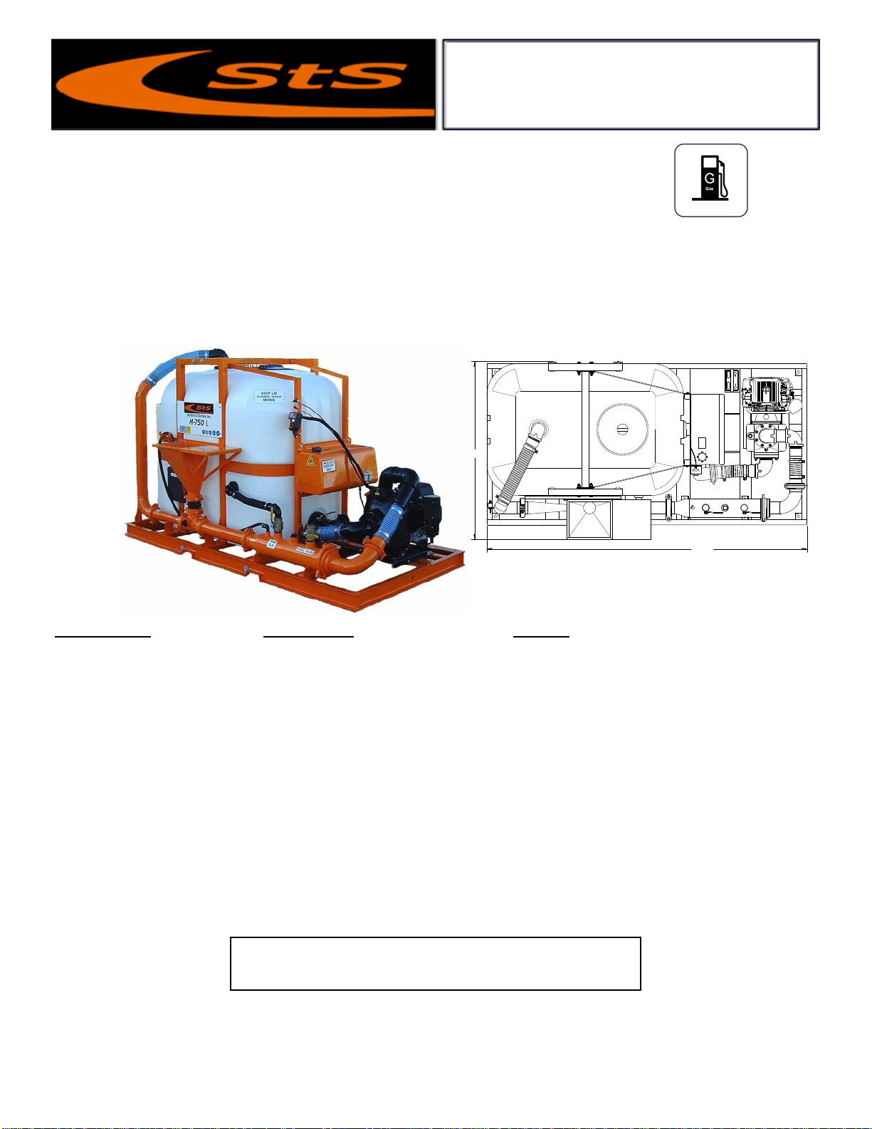
The M-750 mixing unit was designed to mix dry or liquid drilling products with clean
water, into a slurry. The slurry is continually circulated through the mixing cycle until it
reaches the desired consistency. The operator can then transfer the final product to a holding
reservoir or directly to the drilling equipment.
The M-750 mixing unit consists of a 750 u.s. gal. (2839 litre) polyethylene plastic tank,
gasoline or diesel powered centrifugal pump, filter/shear unit, venturi mixing tee assembly,
dry hopper with a table, tank internal jet gun and a discharge valve to pump the finished
slurry to a holding tank or the drill rig. These components are all mounted on a frame type
skid, built for lifting or solid mounting. For ease of interpretation, looking at the mixing unit
hopper straight on will be considered looking at the front of the unit. Hence the other long
side, will be the rear and the ends will be right or left end.
RECORD OF OWNERSHIP:
• Unit Serial No. __________________________________________
• Engine Serial No.________________________________________
• Pump Serial No:_________________________________________
• Tank Serial No:__________________________________________
• Date Purchased/Leased:___________________________________
• Dealer Purchased/Leased From:_____________________________
• Special Custom Features:__________________________________
13
REV.
DATE.
DWR. NUM.
116.50"
65.00"
* Due to our continuing product improvement, specifications are subject to change without notice. *
UNLEADED
GASOLINE
ONLY
Surface to Surface Inc.
DRY WEIGHT
2010 lbs.
M-750L (Gasoline )
M-750L (GR)
10 / 15 / 09
Height: 73"
14
Surface to Surface Inc.
Specifications M-750L Mixer Benefits
Dimensions 65” W x 116.5” L x 75” H The long design allows for alternative
Approx. Weight 2010 Lbs placement by the contractor.
Hopper Height 39” High Waist high hopper reduces back strain.
Mixing System 4” Proprietary StS Mixing System Fast, efficient mixing time ( 8 min. mix ).
Mixing Tank 750 gal. Roto-Molded polyethylene Minimal maintenance required.
Skid Frame 5” Steel channel, welded Built for the rigors of the construction trade.
Gasoline Engine 18.0 hp air-cooled, electric start Industrial rated for long service life.
Pump 4” Cast iron centrifugal trash pump Rugged & repairable for extended service life.
Pump Drive Direct coupled engine to pump No expensive couplers or inserts to replace.
Fuel Tank 15 gal. Steel c/w sight gauge Provides a full day running on a fill up.
Pipe Couplers Bolt & Snap-groove type Provides fast cold weather draining of system.
Pressure Wand Hopper maintenance wand Removal of blockages caused by additives.
Tank Drain Bottom tank drain supplied Provides fast cold weather tank drainage.
Also available in Diesel (M-750LD) - Hydraulic (M-750LH) – Electric (M-750LE) models.
∗∗∗ All Specifications Subject to Change Without Notice ∗∗∗
Features and Benefits M-750L Mixer
The M-750L was designed and manufactured to provide an alternative footprint for special applications. The longer,
narrower footprint allows the contractor the option of mounting the unit to one side of a 96 inch platform, while allowing
a 31 inch walk way and work area in front of the mixer. Powered by an 18.0 hp Air Cooled electric start engine, driving
a 4 inch centrifugal pump making effective use of the proprietary StS mixing system, this Bentonite Mud Mixer is
capable of providing 750 gallons of full yield mud to your drill rig in less then eight (8) minutes. Added benefits to this
unit include the ability to draw water from a second tank and send mud to your drilling rig or storage tank with-out the
use of a second pump. Other power drives available
Bentonite Mud Mixer
Model M-750L
Surface to Surface Inc.
5150 Forest Road, R.R.#3, Watford, Ontario, N0M 2S0
Tel: 1-800-567-0978
Check our website for the latest products and specifications
www.stsmixers.com
01/29/10
116.50"
6
5.00"
UNLEADED
GASOLINE
ONLY
15
M-750LG
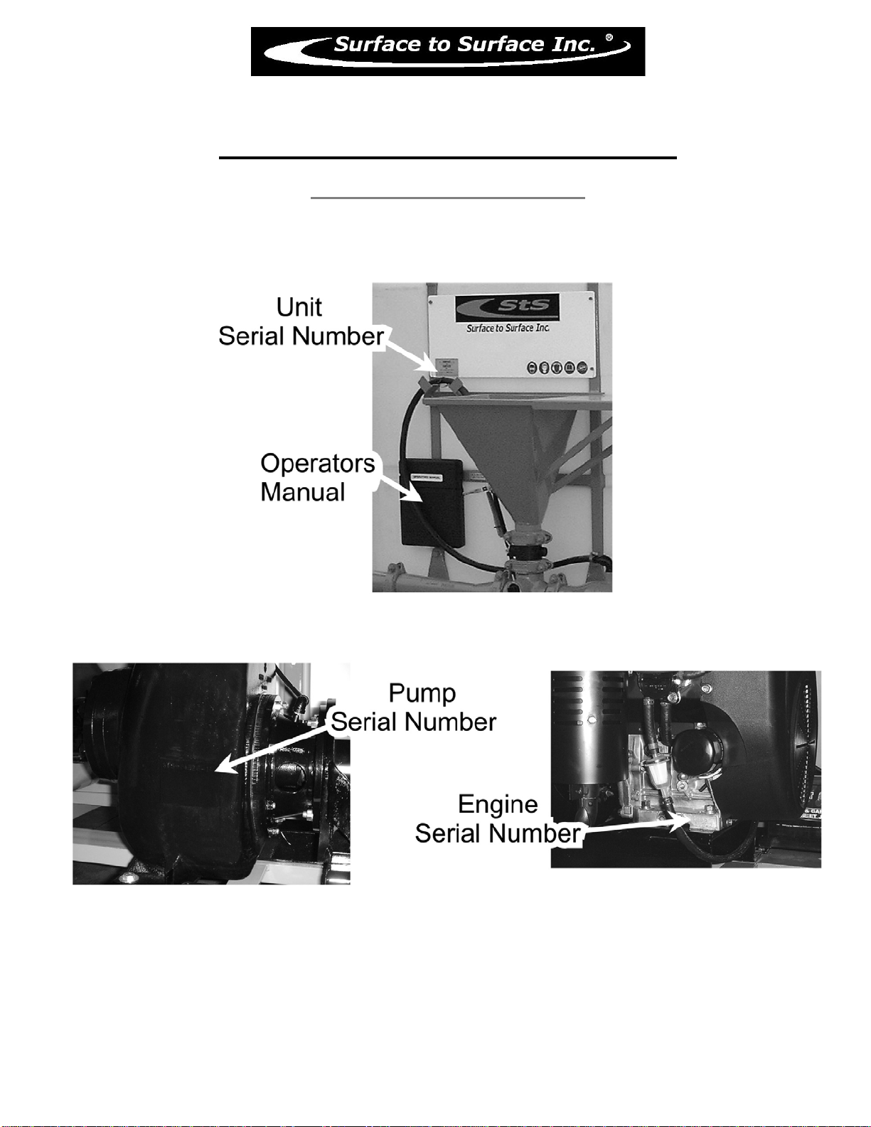
Identifying Your Machine & Components
Location of Tags and PIN Plates

16
SECTION #II
Description, Care and Maintenance
17
M-750LG
Description, Care and Maintenance
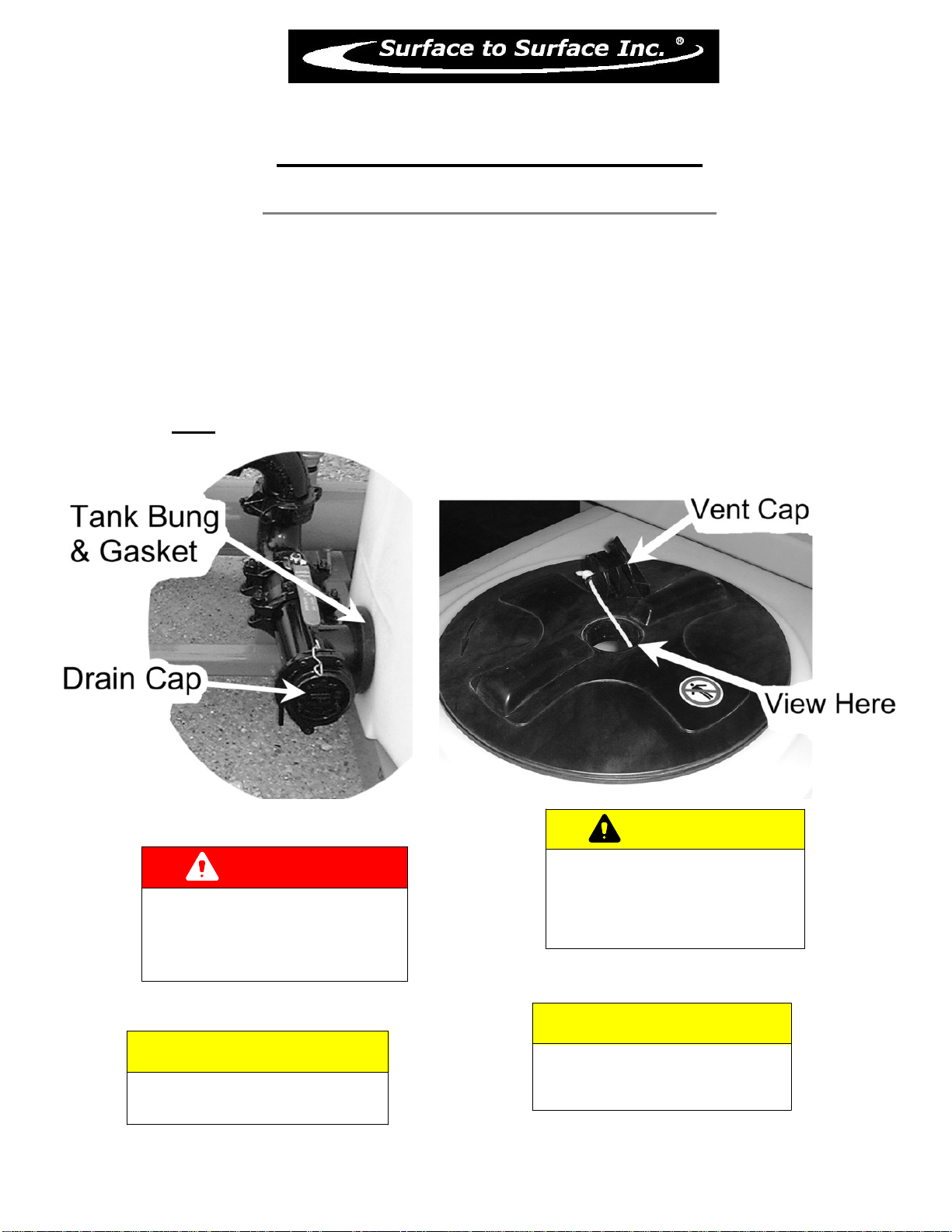
Polyethylene Plastic Reservoir Tank (750 us. gal)
Maintenance of this tank is required, but is simple. The tank should be cleaned on a regular basis by opening
the drain cap on the tank tee, located at the bottom right end of the tank (see Fig.1) and or open the
customer installed bottom tank drain (see Fig.2) and rinse the tank with clear water. Residue such as leaves,
stones, etc can be removed using a wet /dry vacuum.
All tank ports are of a threaded type bung (see Fig.1) with rubber gaskets. If a leak is noticed between
the tank and gasket, the connection can be tightened up by tightening the large nut flange in the direction of
the arrows (counter clock wise).
DANGER
NEVER ATTEMPT REPAIRS
OR DISASSEMBLY
without shutting off the engine / motor
and disconnecting the power source.
Serious personal injury will result.
CAUTION
NEVER OPERATE THE MIXING
unit with the tank lid open.
If viewing is necessary, open
only the small inspection
vent cap in the center of the lid.
CAUTION
BEFORE LIFTING OR MOVING THE UNIT,
all fluid should be removed from the tank.
CAUTION
TO ENTER THE TANK is not recommended
Personal injury could result from
the presents of hazardous fumes,
remaining fluid or unit start-up.
Fig.1

18
M-750LG
Description, Care and Maintenance
Polyethylene Plastic Reservoir Tank (750 us. gal)
INSTALLATION OF (CUSTOMER INSTALLED) TANK DRAIN
• Find a suitable location on the tank floor for the drain to be installed, taking into consideration the
placement of the unit on a trailer. LOOK under the deck for obstructions (cross-members, wiring, and axles,
ect.) Allow room for a shut off valve.
• Drill holes into floor of tank using the top (inside) portion of the drain as the template.
• Make sure the holes are free of burs and both surfaces are clean.
• Install the drain bung as per FIG 1. Note the gaskets are on the inside and outside of the tank.
• Tighten nuts as to slightly squeeze the rubber gaskets.
• Cut a hole into the deck of the trailer or truck for the piping and valve to be installed.
• Install 2” pipe nipple and valve into tank bung with a sealant on the threads. CAUTION: DO NOT OVER-
TIGHTEN!
• The nipple and valve should not extend to far from the tank without a support, as this will cause excess
stress on the threads, drain bung and the tank floor.
• Fill with water and check for leaks.
GASKETS
CUSTOMER SUPPLIED
PIPING AND VALVE
TOP
(INSIDE)
BOTTOM
(OUTSIDE)
FIG 1
TANK FLOOR
1 3/4" Ø
IN FLOOR
Fig.2

19
M-750LG
Description, Care and Maintenance
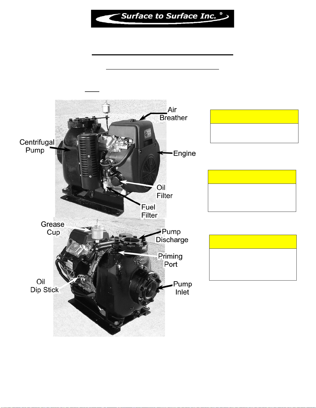
Gasoline Powered Centrifugal Pump
Care and maintenance of the engine and pump are covered in this manual and/or the manufacturer
operator’s manuals supplied and should be read and understood. We suggest the following daily checks be
carried out prior to using the system. Check the gasoline fuel tank is full. Check oil level by removing the oil
plug / dip stick, and viewing the oil level. Check the pump seal grease cup is full (see grease cup instructions
Fig.5). Check the engine air filter (due to environmental conditions). Check that the suction valve (see Fig.3)
is open and the reservoir tank has sufficient liquid to supply the centrifugal pump.
The pump is mounted directly to the engine, so there is no “drive coupler” to check or maintain. The
pump is the primary component that will see the most wear due to the nature of the material it is handling
therefore it will require regular checks, adjustments and maintenance.
There is a section of this manual dedicated to the pump itself and should be read and understood
which will help should any problems or concerns arise in the field.
The pump should never be allowed to start or run dry, as this WILL damage the internal pump seal (grease
seal) and render the unit inoperable until the seal is fixed.
To prime the pump or check to visually see if the pump is primed, slowly undo the plug on top of the
pump beside thedischarge elbow (see Fig.4) and stop after about 3 turns. If the pump is primed, fluid & air
will escape from around the plug threads. This indicates that the pump housing is full, and the plug can be
tightened back up. If no fluid is escaping from around the threads, completely remove the plug.
Fluid or water can be poured into this opening to fill the pump cavity, and a visual of the fluid level inside
the pump can be made. The level should be approximately to the top of the pump housing.
Another way to prime the pump is to have the tank FULL of fluid, and standing off to the side of the
hopper, rotate the hopper valve SLOWLY to the open position. As the valve is opened, you will hear air
escaping followed by fluid, into the hopper itself. Close the valve as the fluid enters the hopper. This means
the fluid in the tank has filled the pump cavity of the pump and flowed from the outlet of the pump to the
remaining piping on the unit.
DANGER
NEVER ATTEMPT REPAIRS
OR DISASSEMBLY
without shutting off the engine / motor
and disconnecting the power source.
Serious personal injury will result.
CAUTION
IMPROPER INSTALLATION OF THE
MECHANICAL or GREASE SEAL
will result in leakage and possible
damage to the seal. All maintenance,
operating and repair of this unit, must be
done per the instructions in the operators
manual for safety and reliability.
Fig.3
CAUTION
BEFORE STARTING THE ENGINE,
BE SURE THE PUMP IS PRIMED!
Check the pump by slowly & carefully
opening the plug located on the top
of the centrifugal pump discharge elbow.
A visual inspection can be made if the fluid
escapes around the plug as it is loosened.
Remove the plug to view inside fluid level.
The centrifugal pump seal WILL be
damaged if allowed to cavitate or run dry.
DANGER
IN AN EMERGENCY
rotate the key switch to
the STOP position
to halt engine, pump, and fluid flow
20
M-750LG
Description, Care and Maintenance
Gasoline Powered Centrifugal Pump
CAUTION
NEVER LEAVE LIQUID IN THE
PUMP CASING, PIPING, OR HOSES
during freezing weather conditions,
as damage will result.
Follow instruction for winterizing.
CAUTION
BEFORE STARTING OR RESTARTING
the engine and centrifugal pump, make
sure any valves installed on the pump
suction inlet line are open, and the
fluid level in the tank is above
the suction line.
CAUTION
TRAPPED FLUID MAY BE PRESENT
and will spill out when piping, hoses,
pump or filter shear are removed.
Fig.4
This manual suits for next models
1
Table of contents
Other STS Music Mixer manuals


