- 3 –
WARNINGS:
zMainsboost systems must not be used for any other
application without the written consent of Stuart
Turner Limited.
zThis appliance can be used by children aged from
8 years and above and persons with reduced
physical, sensory or mental capabilities or lack of
experience and knowledge if they have been given
supervision or instruction concerning use of the
appliance in a safe way and understand the hazards
involved.
zChildren shall not play with the appliance.
zCleaning and user maintenance shall not be made by
children without supervision.
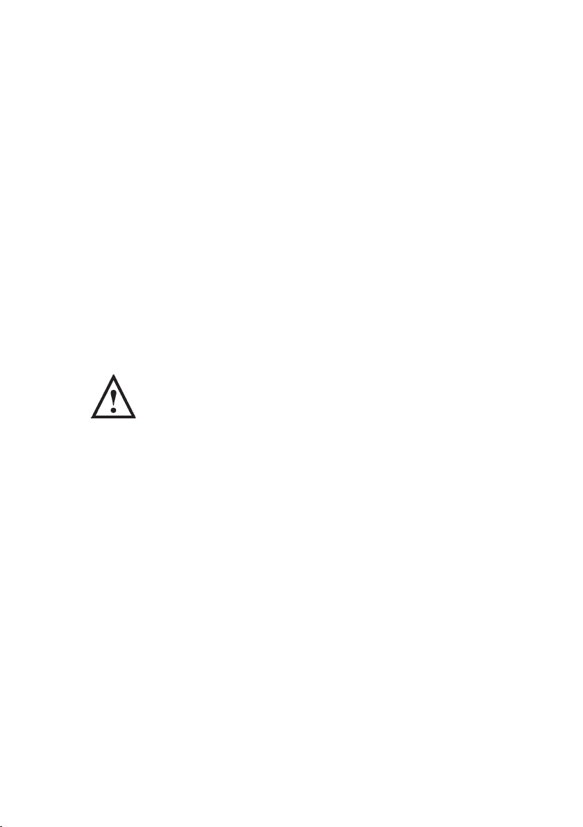
zEnsure the floor is sufficiently strong enough to
take the total weight of the unit when full of water
(see Technical Specification section). Take care when
manoeuvring the unit so as not to damage it.
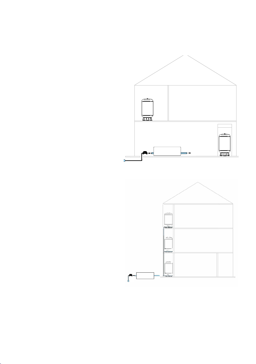
zEnsure the unit is fixed to the floor using suitable
fixings to avoid risk of toppling over.
zTo prevent personal injury, ensure all water pressure
is released from the pressure system prior to
work being performed. Ensure pumps are
disconnected and/or electrically isolated.
zIt is strongly recommended that the system is
protected by a suitable pressure relief valve set at
or below the maximum vessel pressure rating. Failure
to install a pressure relief valve may result in vessel
explosion in the event of a system malfunction or
over pressurisation, resulting in property damage,
serious personal injury or death.
zIf the Mainsboost vessel leaks or shows signs of
corrosion or damage do not use it.
Please read the installation details carefully as they are intended to ensure this
product provides long, trouble free service. Failure to install the unit in accordance
with the installation instructions will lead to invalidation of the warranty. These
instructions must be left with the product.