Studer D19 MicVALVE User manual

D19 MicVALVE
Valve-Dignified Mic/Line Preamplifier
Betriebsanleitung
Operating Instructions
POWER
MicVALVE D19 SERIES
PEAKHOLD SOFT CLIP
MODE SYNC
HOLD SOFT
48
44
VAR
INT
WCLK
AES
AUTO
16DI
16NS
20BIT
INSERT
VALVE 48V
ROUTING Ø
INSERT
VALVE 48 V
ROUTING Ø
OVL
-1
-3
-6
-9
-12
-18
-24
-30
-40
-60
OVL
-1
-3
-6
-9
-12
-18
-24
-30
-40
-60
VALVE
INS
PRE
48 V
Ø
1
2
3
4
5
6
7
8
1
2
3
4
5
6
7
8
VALVE
INS
PRE
48 V
Ø
LEFT
ValveDrive
OFF
0
3
6 9
dB
12
15
Fine
Gain Bass
Warmth
warm
cold
0
2
4 6
1
3
5
7
8
9
10
Angel
Zoom
max.
min.
0
2
4 6
1
3
5
7
8
9
10 dB
Gain
0
2
4 6
1
3
5
7
8
9
10 soft
Clip
hard 4
8
12 16
dBuFS
6
10
14
18
20
22
24
Line
Out
0
2
4 6
1
3
5
7
8
9
10
Input
dBuFS
+24
+10
-10
+20
0
-20
-30
-40
+14
Line Mic
RIGHT
Valve Drive
OFF
0
3
6 9
dB
12
15
Fine
Gain Bass
Warmth
warm
cold
0
2
4 6
1
3
5
7
8
9
10
Angel
Zoom
max.
min.
0
2
4 6
1
3
5
7
8
9
10 dB
Gain
0
2
4 6
1
3
5
7
8
9
10 soft
Clip
hard 4
8
12 16
dBuFS
6
10
14
18
20
22
24
Line
Out
0
2
4 6
1
3
5
7
8
9
10
Input
dBuFS
+24
+10
-10
+20
0
-20
-30
-40
+14
Line Mic

Prepared and edited by Copyright by Studer Professional Audio AG
Studer Professional Audio AG Printed in Switzerland
Technical Documentation Order no. 10.27.3861 (Ed. 0497)
Althardstrasse 30
CH-8105 Regensdorf – Switzerland
http://www.studer.ch Subject to change
Studer is a registered trade mark of Studer Professional Audio AG, Regensdorf

SAFETY / SECURITE / SICHERHEIT
I
To reduce the risk of electric shock, do not remove covers (or
back). No user-serviceable parts inside. Refer servicing to quali-
fied service personnel.
Afin de prévenir un choc électrique, ne pas enlever les couvercles
(où l’arrière) de l’appareil. Il ne se trouve à l’intérieur aucune
pièce pouvant être réparée par l’usager.
Um die Gefahr eines elektrischen Schlages zu vermeiden, entfer-
nen Sie keine Geräteabdeckungen (oder die Rückwand). Über-
lassen Sie Wartung und Reparatur qualifiziertem Fachpersonal.
This symbol is intended to alert the user to presence of uninsula-
ted “dangerous voltage” within the apparatus that may be of suf-
ficient magnitude to constitute a risk of electric shock to a person.
Ce symbole indique à l'utilisateur qu'il existent à l'intérieur de
l'appareil des “tensions dangereuses”. Ces tensions élevées en-
trainent un risque de choc électrique en cas de contact.
Dieses Symbol deutet dem Anwender an, dass im Geräteinnern die
Gefahr der Berührung von “gefährlicher Spannung” besteht. Die
Grösse der Spannung kann zu einem elektrischen Schlag führen.
This symbol is intended to alert the user to the presence of
important instructions for operating and maintenance in the en-
closed documentation.
Ce symbole indique à l’utilisateur que la documentation jointe
contient d'importantes instructions concernant le fonctionnement
et la maintenance.
Dieses Symbol deutet dem Anwender an, dass die beigelegte Do-
kumentation wichtige Hinweise für Betrieb und Wartung enthält.
CAUTION: Lithium battery. Danger of explosion by incorrect handling. Re-
place by battery of the same make and type only.
ATTENTION: Pile au lithium. Danger d'explosion en cas de manipulation incor-
recte. Ne remplacer que par un modèle de même type.
ACHTUNG: Explosionsgefahr bei unsachgemässem Auswechseln der Lithium-
batterie. Nur durch den selben Typ ersetzen.
ADVARSEL: Lithiumbatterei. Eksplosinsfare. Udskinftning ma kun foretages af
en sagkyndig of som beskrevet i servicemanualen (DK).

SAFETY / SECURITE / SICHERHEIT
II
FIRST AID
(in case of electric shock)
1. Separate the person as quickly
as possible from the electric
power source:
•by switching off the equipment
•or by unplugging or disconnec-
ting the mains cable
•pushing the person away from
the power source by using dry
insulating material (such as
wood or plastic).
•After having sustained an elec-
tric shock, always consult a
doctor.
WARNING!
DO NOT TOUCH THE PERSON
OR HIS CLOTHING BEFORE
THE POWER IS TURNED OFF,
OTHERWISE YOU STAND
THE RISK OF SUSTAINING
AN ELECTRIC SHOCK AS
WELL!
2. If the person is unconscious:
•check the pulse,
•reanimate the person if respira-
tion is poor,
•lay the body down, turn it to one
side, call for a doctor immed-
iately.
PREMIERS SECOURS
(en cas d'électrocution)
1. Si la personne est dans l'impos-
sibilité de se libérer:
•Couper l'interrupteur principal
•Couper le courant
•Repousser la personne de l'ap-
pareil à l'aide d'un objet en ma-
tière non conductrice (matière
plastique ou bois)
•Après une électrocution, tou-
jours consulter un médecin.
ATTENTION!
NE JAMAIS TOUCHER UNE
PERSONNE QUI EST SOUS
TENSION, SOUS PEINE DE
SUBIR EGALEMENT UNE
ELECTROCUTION.
2. En cas de perte de connaissance
de la personne électrocutée:
•Controller le pouls
•Si nécessaire, pratiquer la respi-
ration artificielle
•Placer l'accidenté sur le flanc et
consulter un médecin.
ERSTE HILFE
(bei Stromunfällen)
1. Bei einem Stromunfall die be-
troffene Person so rasch wie
möglich vom Strom trennen:
•Ausschalten des Gerätes
•Ziehen oder Unterbrechen der
Netzzuleitung
•Betroffene Person mit isoliertem
Material (Holz, Kunststoff) von
der Gefahrenquelle wegstossen
•Nach einem Stromunfall sollte
immer ein Arzt aufgesucht wer-
den.
ACHTUNG!
EINE UNTER SPANNUNG
STEHENDE PERSON DARF
NICHT BERÜHRT WERDEN.
SIE KÖNNEN DABEI SELBST
ELEKTRISIERT WERDEN!
2. Bei Bewusstlosigkeit des Verun-
fallten:
•Puls kontrollieren,
•bei ausgesetzter Atmung künst-
lich beatmen,
•Seitenlagerung des Verunfallten
vornehmen und Arzt verstän-
digen.

SICHERHEIT / SAFETY
III
Installation
Vor der Installation des Gerätes müssen die hier aufge-
führten und auch die weiter in dieser Anleitung mit
bezeichneten Hinweise gelesen und während der
Installation und des Betriebes beachtet werden.
Untersuchen Sie das Gerät und sein Zubehör auf allfäl-
lige Transportschäden.
Ein Gerät, das mechanische Beschädigung aufweist
oder in welches Flüssigkeit oder Gegenstände einge-
drungen sind, darf nicht ans Netz angeschlossen oder
muss sofort durch Ziehen des Netzsteckers vom Netz
getrennt werden. Das Öffnen und Instandsetzen des
Gerätes darf nur von Fachpersonal unter Einhaltung der
geltenden Vorschriften durchgeführt werden.
Falls dem Gerät kein konfektioniertes Netzkabel
beiliegt, muss dieses durch eine Fachperson unter
Verwendung der mitgelieferten Kabel-Gerätedose
IEC320/C13 oder IEC320/C19 und unter Berücksichti-
gung der einschlägigen, im geweiligen Lande geltenden
Bestimmungen angefertigt werden; siehe unten.
Vor Anschluss des Netzkabels an die Netzsteckdose
muss überprüft werden, ob die Stromversorgungs- und
Anschlusswerte des Gerätes (Netzspannung, Netz-
frequenz) innerhalb der erlaubten Toleranzen liegen.
Die im Gerät eingesetzten Sicherungen müssen den am
Gerät angebrachten Angaben entsprechen.
Ein Gerät mit einem dreipoligen Gerätestecker (Gerät
der Schutzklasse I) muss an eine dreipolige Netzsteck-
dose angeschlossen und somit das Gerätegehäuse mit
dem Schutzleiter der Netzinstallation verbunden werden
(Für Dänemark gelten Starkstrombestimmungen, Ab-
schnitt 107).
Installation
Before you install the equipment, please read and adhe-
re to the following recommendations and all sections of
these instructions marked with .
Check the equipment for any transport damage.
A unit that is mechanically damaged or which has been
penetrated by liquids or foreign objects must not be
connected to the AC power outlet or must be immedia-
tely disconnected by unplugging the power cable. Re-
pairs must only be performed by trained personnel in
accordance with the applicable regulations.
Should the equipment be delivered without a matching
mains cable, the latter has to be prepared by a trained
person using the attached female plug (IEC320/C13 or
IEC320/C19) with respect to the applicable regulations
in your country - see diagram below.
Before connecting the equipment to the AC power out-
let, check that the local line voltage matches the equip-
ment rating (voltage, frequency) within the admissible
tolerance. The equipment fuses must be rated in accor-
dance with the specifications on the equipment.
Equipment supplied with a 3-pole appliance inlet
(equipment conforming to protection class I) must be
connected to a 3-pole AC power outlet so that the
equipment cabinet is connected to the protective earth
conductor of the AC supply (for Denmark the Heavy
Current Regulations, Section 107, are applicable).
Female plug (IEC320), view from contact side:
Llive; brown National American Standard: Black
Nneutral; blue White
PE protective earth; green and yellow green
Connecteur femelle (IEC320), vue de la face aux contacts:
Lphase; brun Standard national américain: Noir
Nneutre; bleu Blanc
PE terre protective; vert et jaune Vert
Ansicht auf Steckkontakte der Kabel-Gerätesteckdose (IEC320):
LPhase; braun USA-Standard: Schwarz
NNulleiter; blau Weiss
PE Schutzleiter; gelb/grün grün

SICHERHEIT / SAFETY
IV
Zugentlastung für den Netzanschluss
Zum Verankern von Steckverbindungen ohne mechani-
sche Verriegelung (z.B. IEC-Kaltgerätedosen) empfeh-
len wir die folgende Anordnung:
Vorgehen: Der mitgelieferte Kabelhalter ist selbstkle-
bend. Bitte beachten Sie bei der Montage die folgenden
Regeln:
1. Der Untergrund muss sauber, trocken und frei von
Fett, Öl und anderen Verunreinigungen sein. Tempe-
raturbereich für optimale Verklebung: 20...40° C.
2. Entfernen Sie die Schutzfolie auf der Rückseite des
Kabelhalters und bringen sie ihn mit kräftigem
Druck an der gewünschten Stelle an. Lassen sie ihn
unbelastet so lange wie möglich ruhen – die maxi-
male Klebekraft ist erst nach rund 24 Stunden er-
reicht.
3. Die Stabilität des Kabelhalters wird erhöht, wenn
Sie ihn zusätzlich verschrauben. Zu diesem Zweck
liegen ihm eine selbstschneidende Schraube sowie
eine M4-Schraube mit Mutter bei.
4. Legen Sie das Kabel gemäss Figur in den Halter ein
und pressen Sie die Klemme kräftig auf, bis das Ka-
bel fixiert ist.
Mains connector strain relief
For anchoring connectors without a mechanical lock
(e.g. IEC mains connectors), we recommend the fol-
lowing arrangement:
Procedure: The cable clamp shipped with your unit is
auto-adhesive. If mounting, please follow the rules be-
low:
1. The surface to be adhered to must be clean, dry, and
free from grease, oil or other contaminants. Best ap-
plication temperature range is 20...40° C.
2. Remove the plastic protective backing from the rear
side of the clamp and apply it firmly to the surface
at the desired position. Allow as much time as pos-
sible for curing. The bond continues to develop for
as long as 24 hours.
3. For improved stability, the clamp can be fixed with
a screw. For this purpose, a self-tapping screw and
an M4 bolt and nut are included.
4. Place the cable into the clamp as shown in the illus-
tration above and firmly press down the internal top
cover until the cable is fixed.

UMGEBUNGSBEDINGUNGEN / AMBIENT CONDITIONS
V
Lufttemperatur und Feuchtigkeit
Allgemein
Die Betriebstauglichkeit des Gerätes oder Systems ist unter
folgenden Umgebungsbedingungen gewährleistet:
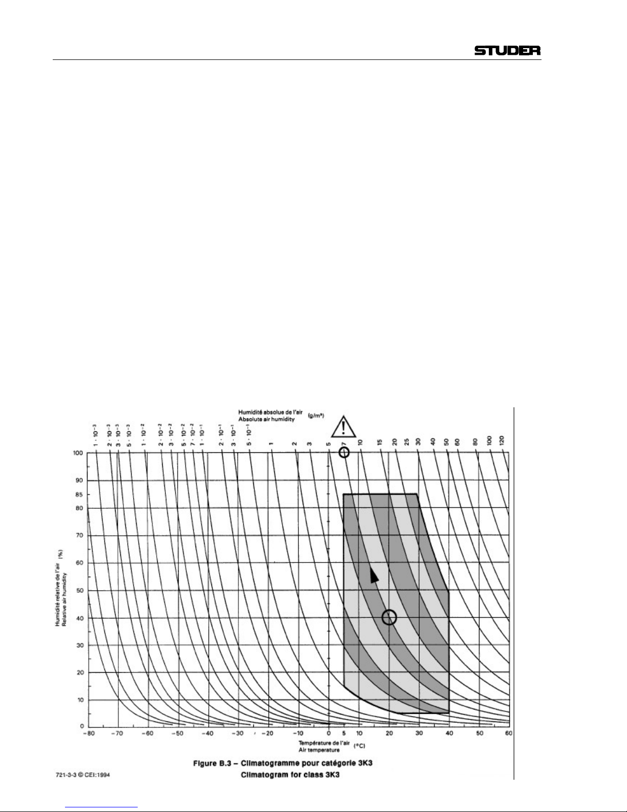
EN 60721-3-3, Set IE32, Wert 3K3.
Diese Norm umfasst einen umfassenden Katalog von Parame-
tern; die wichtigsten davon sind: Umgebungstemperatur
+5...+40 °C; rel. Luftfeuchtigkeit 5...85% – d.h. weder Konden-
sation noch Eisbildung; abs. Luftfeuchtigkeit 1...25 g/m³; Tem-
peratur-Änderungsrate <0,5 °C/min. In den folgenden Ab-
schnitten wird darauf näher eingegangen.
Unter den genannten Bedingungen startet und arbeitet das
Gerät oder System problemlos. Ausserhalb dieser Spezifikatio-
nen möglicherweise auftretende Probleme sind in den folgenden
Abschnitten beschrieben.
Umgebungstemperatur
Geräte und Systeme von Studer sind allgemein für einen Um-
gebungstemperaturbereich (d.h. Temperatur der eintretenden
Kühlluft) von +5...+40 °C ausgelegt. Bei Installation in einem
Schrank muss der vorgesehene Luftdurchsatz und dadurch die
Konvektionskühlung gewährleistet sein. Folgende Tatsachen
sind dabei zu berücksichtigen:
1. Die zulässige Umgebungstemperatur für den Betrieb der
Halbleiter-Bauelemente beträgt 0°C bis +70 °C (commercial
temperature range for operation).
2. Der Luftdurchsatz der Anlage muss gewährleisten, dass die
austretende Kühlluft ständig kühler ist als 70 °C.
3. Die mittlere Erwärmung der Kühlluft soll 20 K betragen,
die maximale Erwärmung an den heissen Komponenten darf
somit um weitere 10 K höher liegen.
4. Zum Abführen einer Verlustleistung von 1kW bei dieser
zulässigen mittleren Erwärmung ist eine Luftmenge von
2,65 m³/min notwendig.
Beispiel: Für ein Rack mit einer Leistungsaufnahme P = 800 W
ist eine Kühlluftmenge von 0,8 * 2,65 m³/min nötig, entspre-
chend 2,12 m³/min.
5. Soll die Kühlfunktion der Anlage (z.B. auch bei Lüfter-
Ausfall oder Bestrahlung durch Spotlampen) überwacht wer-
den, so ist die Temperatur der Abluft unmittelbar oberhalb der
Einschübe an mehreren Stellen im Rack zu messen; die An-
sprechtemperatur der Sensoren soll 65 bis 70 °C betragen.
Reif und Tau
Das unversiegelte System (Steckerpartien, Halbleiteranschlüs-
se) verträgt zwar leichte Eisbildung (Reif). Mit blossem Auge
sichtbare Betauung führt jedoch bereits zu Funktionsstörungen.
In der Praxis kann mit einem zuverlässigen Betrieb der Geräte
bereits im Temperaturbereich ab –15 °C gerechnet werden,
wenn für die Inbetriebnahme des kalten Systems die folgende
allgemeine Regel beachtet wird:
Wird die Luft im System abgekühlt, so steigt ihre relative
Feuchtigkeit an. Erreicht diese 100%, kommt es zu Nieder-
schlag, meist in der Grenzschicht zwischen der Luft und einer
kühleren Oberfläche, und somit zur Bildung von Eis oder Tau
an empfindlichen Systemstellen (Kontakte, IC-Anschlüsse etc.).
Ein störungsfreier Betrieb mit interner Betauung, unabhängig
von der Temperatur, ist nicht gewährleistet.
Air temperature and humidity
General
Normal operation of the unit or system is warranted under the
following ambient conditions defined by:
EN 60721-3-3, set IE32, value 3K3.
This standard consists of an extensive catalogue of parameters,
the most important of which are: ambient temperature +5...
+40° C, relative humidity 5...85% – i.e. no formation of con-
densation or ice; absolute humidity 1...25 g/m³; rate of tem-
perature change <0,5 °C/min. These parameters are dealt with
in the following paragraphs.
Under these conditions the unit or system starts and works
without any problem. Beyond these specifications, possible
problems are described in the following sections.
Ambient temperature
Units and systems by Studer are generally designed for an am-
bient temperature range (i.e. temperature of the incoming air) of
+5...+40 °C. When rack mounting the units, the intended air
flow and herewith adequate cooling must be provided. The
following facts must be considered:
1. The admissible ambient temperature range for operation of
the semiconductor components is 0°C to +70 °C (commercial
temperature range for operation).
2. The air flow through the installation must provide that the
outgoing air is always cooler than 70 °C.
3. Average heat increase of the cooling air shall be 20 K, al-
lowing for an additional maximum 10 K increase at the hot
components.
4. In order to dissipate 1 kW with this admissible average heat
increase, an air flow of 2,65 m³/min is required.
Example: A rack dissipating P = 800 W requires an air flow of
0,8 * 2,65 m³/min which corresponds to 2,12 m³/min.
5. If the cooling function of the installation must be monitored
(e.g. for fan failure or illumination with spot lamps), the outgo-
ing air temperature must be measured directly above the mod-
ules at several places within the rack. The trigger temperature of
the sensors should be 65 to 70 °C.
Frost and dew
The unsealed system parts (connector areas and semiconductor
pins) allow for a minute formation of ice or frost. However,
formation of dew visible with the naked eye will already lead to
malfunctions. In practice, reliable operation can be expected in
a temperature range above –15 °C, if the following general rule
is considered for putting the cold system into operation:
If the air within the system is cooled down, the relative humid-
ity rises. If it reaches 100%, condensation will arise, usually in
the boundary layer between the air and a cooler surface, to-
gether with formation of ice or dew at sensitive areas of the
system (contacts, IC pins, etc.). Once internal condensation
occurs, troublefree operation cannot be guaranteed, independent
of temperature.

UMGEBUNGSBEDINGUNGEN / AMBIENT CONDITIONS
VI
Vor der Inbetriebnahme muss das System auf allfällige interne
Betauung oder Eisbildung überprüft werden. Nur bei sehr
leichter Eisbildung kann mit direkter Verdunstung (Sublimati-
on) gerechnet werden; andernfalls muss das System im abge-
schalteten Zustand gewärmt und getrocknet werden.
Das System ohne feststellbare interne Eisbildung oder Betau-
ung soll möglichst homogen (und somit langsam) mit eigener
Wärmeleistung aufgewärmt werden; die Lufttemperatur der
Umgebung soll ständig etwas tiefer als diejenige der Syste-
mabluft sein.
Ist es unumgänglich, das abgekühlte System sofort in warmer
Umgebungsluft zu betreiben, so muss diese entfeuchtet sein.
Die absolute Luftfeuchtigkeit muss dabei so tief sein, dass die
relative Feuchtigkeit, bezogen auf die kälteste Oberfläche im
System, immer unterhalb 100% bleibt.
Es ist dafür zu sorgen, dass beim Abschalten des Systems die
eingeschlossene Luft möglichst trocken ist (d.h. vor dem Ab-
schalten im Winter den Raum mit kalter, trockener Luft belüf-
ten und feuchte Gegenstände, z.B. Kleider, entfernen).
Die Zusammenhänge sind im folgenden Klimatogramm er-
sichtlich. Zum kontrollierten Verfahren gehören Thermometer
und Hygrometer sowie ein Thermometer innerhalb des Systems.
Beispiel 1: Ein Ü-Wagen mit einer Innentemperatur von 20 °C
und 40% relativer Luftfeuchtigkeit wird am Abend abgeschal-
tet. Sinkt die Temperatur unter +5 °C, bildet sich Tau oder Eis.
Beispiel 2: Ein Ü-Wagen wird morgens mit 20 °C warmer Luft
von 40% relativer Luftfeuchtigkeit aufgewärmt. Auf Teilen, die
kälter als +5 °C sind, bildet sich Tau oder Eis.
Before putting into operation, the system must be checked for
internal formation of condensation or ice. Only with a minute
formation of ice, direct evaporation (sublimation) may be ex-
pected; otherwise the system must be heated and dried while
switched off.
A system without visible internal formation of ice or condensa-
tion should be heated up with its own heat dissipation, as ho-
mogeneously (and subsequently as slow) as possible; the ambi-
ent temperature should then always be lower than the outgoing
air.
If it is absolutely necessary to operate the system immediately
within warm ambient air, this air must be dehydrated. In such a
case, the absolute humidity must be so low that the relative
humidity, related to the coldest system surface, always remains
below 100%.
Ensure that the enclosed air is as dry as possible when powe-
ring off (i.e. before switching off in winter, aerate the room with
cold, dry air, and remove humid objects as clothes from the
room).
These relationships are visible from the following climatogram.
For a controlled procedure, thermometer and hygrometer as well
as a thermometer within the system will be required.
Example 1: An OB-van having an internal temperature of
20 °C and rel. humidity of 40% is switched off in the evening.
If temperature falls below +5 °C, dew or ice will be forming.
Example 2: An OB-van is heated up in the morning with air of
20 °C and a rel. humidity of 40%. On all parts being cooler than
+5 °C, dew or ice will be forming.

WARTUNG / MAINTENANCE
VII
Wartung und Reparatur
Durch Entfernen von Gehäuseteilen, Abschirmungen
etc. werden stromführende Teile freigelegt. Deshalb
müssen u.a. die folgenden Grundsätze beachtet werden:
Eingriffe in das Gerät dürfen nur von Fachpersonal
unter Einhaltung der geltenden Vorschriften vorge-
nommen werden.
Vor Entfernen von Gehäuseteilen muss das Gerät aus-
geschaltet und vom Netz getrennt werden.
Bei geöffnetem, vom Netz getrenntem Gerät dürfen
Teile mit gefährlichen Ladungen (z. B. Kondensatoren,
Bildröhren) erst nach kontrollierter Entladung, heiße
Bauteile (Leistungshalbleiter, Kühlkörper etc.) erst
nach deren Abkühlen berührt werden.
Bei Wartungsarbeiten am geöffneten, unter Netz-
spannung stehenden Gerät dürfen blanke Schaltungs-
teile und metallene Halbleitergehäuse weder direkt noch
mit nichtisoliertem Werkzeug berührt werden.
Zusätzliche Gefahren bestehen bei unsachgemässer
Handhabung besonderer Komponenten:
•Explosionsgefahr bei Lithiumzellen, Elektrolyt-Kon-
densatoren und Leistungshalbleitern
•Implosionsgefahr bei evakuierten Anzeigeeinheiten
•Strahlungsgefahr bei Lasereinheiten (nichtioni-
sierend), Bildröhren (ionisierend)
•Verätzungsgefahr bei Anzeigeeinheiten (LCD) und
Komponenten mit flüssigem Elektrolyt.
Solche Komponenten dürfen nur von ausgebildetem
Fachpersonal mit den vorgeschriebenen Schutzmitteln
(u.a. Schutzbrille, Handschuhe) gehandhabt werden.
Maintenance and Repair
The removal of housing parts, shields, etc. exposes
energized parts. For this reason the following precauti-
ons should be observed:
Maintenance should only be performed by trained per-
sonnel in accordance with the applicable regulations.
The equipment should be switched off and disconnected
from the AC power outlet before any housing parts are
removed.
Even if the equipment is disconnected from the power,
parts with hazardous charges (e.g. capacitors, picture
tubes) must not be touched until they have been pro-
perly discharged. Touch hot components (power semi-
conductors, heat sinks, etc.) only when cooled off.
If maintenance is performed on a unit that is opened
and switched on, no uninsulated circuit components and
metallic semiconductor housings must be touched nei-
ther with your bare hands nor with uninsulated tools.
Certain components pose additional hazards:
•Explosion hazard from lithium batteries, electrolytic
capacitors and power semiconductors
•Implosion hazard from evacuated display units
•Radiation hazard from laser units (non-ionizing),
picture tubes (ionizing)
•Caustic effect of display units (LCD) and such com-
ponents containig liquid electrolyte.
Such components should only be handled by trained
personnel who are properly protected (e.g. safety
goggles, gloves).

WARTUNG / MAINTENANCE
VIII
Elektrostatische Entladung (ESD)
bei Wartung und Reparatur
ATTENTION:
ATTENTION:
ACHTUNG:
Viele ICs und andere Halbleiter sind empfindlich gegen
elektrostatische Entladung (ESD). Unfachgerechte Be-
handlung von Baugruppen mit solchen Komponenten
bei Wartung und Reparatur kann deren Lebensdauer
drastisch vermindern.
Bei der Handhabung der ESD-empfindlichen Kompo-
nenten sind u.a. folgende Regeln zu beachten:
•ESD-empfindliche Komponenten dürfen ausschliess-
lich in dafür bestimmten und bezeichneten Ver-
packungen gelagert und transportiert werden.
•Unverpackte, ESD-empfindliche Komponenten dür-
fen nur in dafür eingerichteten Schutzzonen (EPA,
z.B. Gebiet für Feldservice, Reparatur- oder Service-
platz) gehandhabt und nur von Personen berührt
werden, die durch ein Handgelenkband mit Serie-
widerstand mit dem Massepotential des Reparatur-
oder Serviceplatzes verbunden sind. Das gewartete
Gerät wie auch Werkzeug, Hilfsmittel, EPA-
taugliche (elektrisch halbleitende) Arbeits-, Ablage-
und Bodenmatten müssen ebenfalls mit diesem Po-
tential verbunden sein.
•Die Anschlüsse der ESD-empfindlichen Komponen-
ten dürfen unkontrolliert weder mit elektrostatisch
aufladbaren (Gefahr von Spannungsdurchschlag),
noch mit metallischen Oberflächen (Schockent-
ladungsgefahr) in Berührung kommen.
•Um undefinierte transiente Beanspruchung der Kom-
ponenten und deren eventuelle Beschädigung durch
unerlaubte Spannung oder Ausgleichsströme zu ver-
meiden, dürfen elektrische Verbindungen nur am ab-
geschalteten Gerät und nach dem Abbau allfälliger
Kondensatorladungen hergestellt oder getrennt wer-
den.
Electrostatic Discharge (ESD)
during Maintenance and Repair
Observe precautions for handling devices sensitive to
electrostatic discharge!
Respecter les précautions d’usage concernant la mani-
pulation de composants sensibles à l’électricité statique!
Vorsichtsmassnahmen bei Handhabung elektrostatisch
entladungsgefährdeter Bauelemente beachten!
Many ICs and semiconductors are sensitive to elec-
trostatic discharge (ESD). The life of components con-
taining such elements can be drastically reduced by
improper handling during maintenance and repair work.
Please observe the following rules when handling ESD
sensitive components:
•ESD sensitive components should only be stored and
transported in the packing material specifically pro-
vided for this purpose.
•Unpacked ESD sensitive components should only be
handled in ESD protected areas (EPA, e.g. area for
field service, repair or service bench) and only be
touched by persons who wear a wristlet that is con-
nected to the ground potential of the repair or service
bench by a series resistor. The equipment to be repai-
red or serviced and all tools, aids, as well as electri-
cally semiconducting work, storage and floor mats
should also be connected to this ground potential.
•The terminals of ESD sensitive components must not
come in uncontrolled contact with electrostatically
chargeable (voltage puncture) or metallic surfaces
(discharge shock hazard).
•To prevent undefined transient stress of the compo-
nents and possible damage due to inadmissible volta-
ges or compensation currents, electrical connections
should only be established or separated when the
equipment is switched off and after any capacitor
charges have decayed.

WARTUNG / MAINTENANCE
IX
SMD-Bauelemente
Der Austausch von SMD-Bauelementen ist ausschliess-
lich geübten Fachleuten vorbehalten. Für verwüstete
Platinen können keine Ersatzansprüche geltend gemacht
werden. Beispiele für korrekte und falsche SMD-
Lötverbindungen in der Abbildung weiter unten.
Bei Studer werden keine handelsüblichen SMD-Teile
bewirtschaftet. Für Reparaturen sind die notwendigen
Bauteile lokal zu beschaffen. Die Spezifikationen von
Spezialbauteilen finden Sie in der Serviceanleitung.
SMD Components
SMDs should only be replaced by skilled specialists.
No warranty claims will be accepted for circuit boards
that have been ruined. Proper and improper SMD sol-
dering joints are depicted below.
Studer does not keep any commercially available SMDs
in stock. For repair the corresponding devices should be
purchased locally. The specifications of special compo-
nents can be found in the service manual.

EMV / EMC
X
Störstrahlung und Störfestigkeit
Das Gerät entspricht den Schutzanforderungen auf dem
Gebiet elektromagnetischer Phänomene, wie u.a. in den
Richtlinien 89/336/EWG und FCC, Part 15, aufgeführt:
1. Vom Gerät erzeugte elektromagnetische Strahlung ist
soweit begrenzt, dass bestimmungsgemässer Betrieb
anderer Geräte und Systeme möglich ist.
2. Das Gerät weist eine angemessene Festigkeit gegen
elektromagnetische Störungen auf, so dass sein be-
stimmungsgemässer Betrieb möglich ist.
Das Gerät wurde getestet und erfüllt die Bedingungen
der im Kapitel „Technische Daten“ aufgeführten EMV-
Standards. Die Limiten dieser Standards gewährleisten
mit angemessener Wahrscheinlichkeit sowohl den
Schutz der Umgebung wie auch entsprechende Stör-
festigkeit des Gerätes. Absolute Garantie, dass keine
unerlaubte elektromagnetische Beeinträchtigung wäh-
rend des Betriebes entsteht, ist jedoch nicht gegeben.
Um die Wahrscheinlichkeit solcher Beeinträchtigung
weitgehend auszuschliessen, sind u.a. folgende Mass-
nahmen zu beachten:
•Installieren Sie das Gerät gemäss den Angaben in der
Betriebsanleitung, und verwenden Sie das mitgelie-
ferte Zubehör.
•Verwenden Sie im System und in der Umgebung, in
denen das Gerät eingesetzt ist, nur Komponenten
(Anlagen, Geräte), die ihrerseits die Anforderungen
der obenerwähnten Standards erfüllen.
•Sehen Sie ein Erdungskonzept des Systems vor, das
sowohl die Sicherheitsanforderungen (die Erdung der
Geräte gemäss Schutzklasse I mit einem Schutzleiter
muss gewährleistet sein), wie auch die EMV-Belange
berücksichtigt. Bei der Entscheidung zwischen stern-
oder flächenförmiger bzw. kombinierter Erdung sind
Vor- und Nachteile gegeneinander abzuwägen.
•Benutzen Sie abgeschirmte Kabel, wo vorgesehen.
Achten Sie auf einwandfreie, grossflächige, korrosi-
onsbeständige Verbindung der Abschirmung zum
entsprechenden Steckeranschluss und dessen Gehäu-
se. Beachten Sie, dass eine nur an einem Ende ange-
schlossene Kabelabschirmung als Sende- bzw. Emp-
fangsantenne wirken kann (z.B. bei wirksamer Ka-
bellänge von 5m oberhalb von 10 MHz), und dass
die Flanken digitaler Kommunikationssignale hoch-
frequente Aussendungen verursachen (z.B. LS- oder
HC-Logik bis 30 MHz).
•Vermeiden Sie Bildung von Masseschleifen oder ver-
mindern Sie deren unerwünschte Auswirkung, indem
Sie deren Fläche möglichst klein halten und den darin
fliessenden Strom durch Einfügen einer Impedanz
(z.B. Gleichtaktdrossel) reduzieren.
Electromagnetic Compatibility
The equipment conforms to the protection requirements
relevant to electromagnetic phenomena that are listed in
the guidelines 89/336/EC and FCC, part 15.
1. The electromagnetic interference generated by the
equipment is limited in such a way that other equip-
ment and systems can be operated normally.
2. The equipment is adequately protected against elec-
tromagnetic interference so that it can operate cor-
rectly.
The unit has been tested and conforms to the EMC
standards applicable to residential, commercial and
light industry, as listed in the section „Technical Data“.
The limits of these standards reasonably ensure protec-
tion of the environment and corresponding noise immu-
nity of the equipment. However, it is not absolutely
warranted that the equipment will not be adversely af-
fected by electromagnetic interference during operation.
To minimize the probability of electromagnetic interfer-
ence as far as possible, the following recommendations
should be followed:
•Install the equipment in accordance with the opera-
ting instructions. Use the supplied accessories.
•In the system and in the vicinity where the equipment
is installed, use only components (systems, equip-
ment) that also fulfill the above EMC standards.
•Use a system grounding concept that satisfies the
safety requirements (protection class I equipment
must be connected with a protective ground conduc-
tor) that also takes into consideration the EMC requi-
rements. When deciding between radial, surface or
combined grounding, the advantages and disad-
vantages should be carefully evaluated in each case.
•Use shielded cables where shielding is specified. The
connection of the shield to the corresponding con-
nector terminal or housing should have a large sur-
face and be corrosion-proof. Please note that a cable
shield connected only single-ended can act as a
transmitting or receiving antenna (e.g. with an effec-
tive cable length of 5m, the frequency is above
10 MHz) and that the edges of the digital communi-
cation signals cause high-frequency radiation (e.g.
LS or HC logic up to 30 MHz).
•Avoid ground loops or reduce their adverse effects
by keeping the loop surface as small as possible, and
reduce the noise current flowing through the loop by
inserting an additional impedance (e.g. common-
mode rejection choke).

Konformitätserklärungen / Declarations of conformity
XI
Class A Equipment - FCC Notice
This equipment has been tested and found to comply with
the limits for a Class A digital device, pursuant to Part 15
of the FCC Rules. These limits are designed to provide a
reasonable protection against harmful interference when the
equipment is operated in a commercial environment. This
equipment generates, uses, and can radiate radio frequency
energy and, if not installed and used in accordance with the
instruction manual, may cause harmful interference to radio
communications. Operation of this equipment in a residen-
tial area is likely to cause harmful interference in which
case the user will be required to correct the interference at
his own expense.
Caution:
Any changes or modifications not expressly approved by
the manufacturer could void the user's authority to operate
the equipment. Also refer to relevant information in this
manual.
CE-Konformitätserklärung
Der Hersteller,
Studer Professional Audio AG,
CH-8105 Regensdorf,
erklärt in eigener Verantwortung, dass das Produkt
Studer D19 MicVALVE, Valve Dignified Mic/Line Pre-
amplifier, (ab Serie-Nr. 101),
auf das sich diese Erklärung bezieht, entsprechend den
Bestimmungen der EU-Richtlinien und Ergänzungen
•Elektromagnetische Verträglichkeit (EMV):
89/336/EWG + 92/31/EWG + 93/68/EWG
•Niederspannung:
73/23/EWG + 93/68/EWG
mit den folgenden Normen und normativen Dokumenten
übereinstimmt:
•Sicherheit:
Schutzklasse 1, EN 60950:1992 + A1/A2:1993
•EMV:
EN 50081-1:1992, EN 50082:1992.
Regensdorf, 6. Februar 1996
B. Hochstrasser, Geschäftsleiter
P. Fiala, Leiter QS
CE Declaration of Conformity
The manufacturer,
Studer Professional Audio AG,
CH-8105 Regensdorf,
declares under his sole responsibility that the product
Studer D19 MicVALVE, Valve Dignified Mic/Line Pre-
amplifier, (on from serial No. 101),
to which this declaration relates, according to following
regulations of EU directives and amendments
•Electromagnetic Compatibility (EMC):
89/336/EEC + 92/31/EEC + 93/68/EEC
•Low Voltage (LVD):
73/23/EEC + 93/68/EEC
is in conformity with the following standards or other nor-
mative documents:
•Safety:
Class 1, EN 60950:1992 + A1/A2:1993
•EMC:
EN 50081-1:1992, EN 50082:1992.
Regensdorf, February 6, 1996
B. Hochstrasser, Managing director
P. Fiala, Manager QA

D19 MicVALVE
Date printed: 9.2.2000 Contents E0/1
CONTENTS
1Come in!.................................................................................................................................................................E1/1
1.1 Basic Information............................................................................................................................................E1/1
1.2 General............................................................................................................................................................E1/2
1.2.1 Scope of Delivery.....................................................................................................................................E1/2
1.2.2 Options....................................................................................................................................................E1/2
1.2.3 Accessories ..............................................................................................................................................E1/2
1.3 Safety and Connections....................................................................................................................................E1/3
1.3.1 Utilization for the Purpose Intended.........................................................................................................E1/3
1.3.2 Power Connection....................................................................................................................................E1/3
Connector Panel..................................................................................................................................................E1/4
1.4 Technical Specifications..................................................................................................................................E1/6
1.4.1 Audio Specifications................................................................................................................................E1/6
1.4.2 Synchronization.......................................................................................................................................E1/7
1.4.3 Power Supply...........................................................................................................................................E1/7
1.4.4 Primary Fuse............................................................................................................................................E1/8
1.4.5 Operating Conditions...............................................................................................................................E1/8
1.4.6 Safety and EMC Standards.......................................................................................................................E1/8
1.4.7 Mechanical Data......................................................................................................................................E1/8
2Operation...............................................................................................................................................................E2/1
2.1 Operating Elements.........................................................................................................................................E2/1
2.2 Audio and Sync Connections, Pin Assignments...............................................................................................E2/4
2.2.1 Mic and Line Inputs, Insert Returns.........................................................................................................E2/4
2.2.2 Line Outputs, Insert Sends.......................................................................................................................E2/4
2.2.3 AES/EBU, Digital Output........................................................................................................................E2/4
2.2.4 AES IN, External AES/EBU Synchronization..........................................................................................E2/4
2.2.5 Word Clock In/Out..................................................................................................................................E2/4
2.2.6 Using the TDIF-1 8-Channel Interface.....................................................................................................E2/5
2.2.7 Using the Optical ADAT 8-Channel Interface..........................................................................................E2/6
2.3 Application Ideas and Examples......................................................................................................................E2/7
2.3.1 Wiring for External Synchronization .......................................................................................................E2/9
3Additional information..........................................................................................................................................E3/1
3.1 What the Heck is Noise Shaping?....................................................................................................................E3/1
3.2 Block Diagrams...............................................................................................................................................E3/3
3.2.1 Global Audio Block Diagram...................................................................................................................E3/3
3.2.2 Synchronization Block Diagram...............................................................................................................E3/3

D19 MicVALVE
Date printed: 9.2.2000 Come in! E1/1
1COME IN!
We are happy to welcome you in the steadily growing circle of the Studer
D19 MicVALVE's users, and we felicitate you on your selection. Thanks to
Studer's experience collected during more than 40 years of business in the
professional audio products field, you may expect that the performance of
your new unit will fulfill your highest demands.
1.1 Basic Information
Together with the renaissance of natural sounds and the classical recorded
performance of real artists (as opposed to computer-gernerated sounds), us-
ers frequently quote the term “valve sound” in a meaning far beyound nos-
talgic reminiscence. Studer engineers have systematically investigated the
differences between valve and transistor amplifiers. The result of this re-
search is now part of the D19 MicVALVE, where the typical properties of
valve amplifiers are implemented in the form of adjustable parameters.
The MicVALVE is a two-channel preamplifier for microphone and line level
signals with analog and digital outputs. The main signal path is designed in
semiconductor technology and allows top quality “direct-to-digital” record-
ings. A Valve Dignifier stage equipped with 2 × ECC 81 valves per channel
can be switched into the signal path, providing a number of front panel con-
trols for individual valve sound treatment. Each input has a switchable ana-
log insert and an analog output. Both channels are then combined to an
AES/EBU digital output. The built-in 20 bit A/D converter technology rep-
resents today's state of the art. Thanks to the modular concept the A/D con-
verter can easily be upgraded as technology advances. A TDIF or an optical
ADAT interface can be installed as an option.
Even in connection with recording media having only the reduced 16 bit
resolution, the Studer MicVALVE leads to improved results thanks to DSP
dithering and noise shaping technology which is used instead of simple trun-
cating.

D19 MicVALVE
E1/2Come in! Date printed: 9.2.2000
1.2 General
1.2.1 Scope of Delivery
The D19 MicVALVE (order No. 66.655.000.00) is supplied with an IEC
320/C13 socket, a hex-socket-screwdriver (2.5 mm), and this manual.
1.2.2 Options Order No.
Digital Audio Output Options:
ADAT Interface: 8-channel optical digital audio output card 1.650.050.20
for connecting with the ADAT and compatible
8-channel recorders or other equipment featuring
the ADAT standard connectors.
TDIF-1 Interface: 8-channel digital audio output card 1.650.052.20
for connecting with the DA-88 and compatible
8-channel recorders or other equipment featuring
the TDIF-1 standard connectors.
Note: These two options are identical to the ones used for the eight-channel D19
MicAD preamp; the channel routing, however, can be selected individually
on the D19 MicVALVE.
Super ADC: Converter assembly for further improving 1.655.042.00
the A/D performance
1.2.3 Accessories Order No.
Accessories/Spares: Kit, consisting of: 20.020.302.51
•Mating XLR connectors (7 pcs. male,
5 pcs. female)
•Rotary knobs (2 × small, 1 × large)
•Rack mounting screws with washers
(4 pcs. each)
Interface cables: ADAT/Alesis optical interface cable,10.325.010.00
length 1.0 m
ADAT/Alesis optical interface cable,10.325.011.00
length 5.0 m
TDIF-1/Tascam interface cable F-10.025.031.08
“PW 88D”, length 1.0 m
TDIF-1/Tascam interface cable F-10.025.031.09
“PW 88D”, length 5.0 m

D19 MicVALVE
Date printed: 9.2.2000 Come in! E1/3
1.3 Safety and Connections
1.3.1 Utilization for the Purpose Intended
The Studer D19 MicVALVE 2-channel Mic/Line valve preamplifier is de-
signed for professional use. It is presumed that the unit is operated only by
trained personnel; servicing must be performed by qualified experts.
The electrical connections may be connected only to the appropriate volt-
ages and signals specified in this manual. Please consult the Security and
EMC section at the very beginning of this manual.
1.3.2 Power Connection
There is no need to select a specific mains voltage setting because the Studer
D19 MicVALVE can be operated on mains voltages from 100 through
240 VAC, 50...60 Hz.
Danger: Repair work may only be performed by a trained service technician. The
primary fuse of the D19 MicVALVE must be replaced by a spare fuse of
exactly the same type. The D19 MicVALVE must not be opened by the user
– the risk of a severe electric shock hazard is increased as a result of the
high operating voltage of the vacuum tubes (300 V)!
Power cable: The supplied power socket has to be fitted with a mating power cable incl.
plug by an electrician, if your local Studer agency or your dealer should not
have added a fitting power cable.
☛Please consult the Safety section at the very beginning of this manual.

D19 MicVALVE
E1/4Come in! Date printed: 9.2.2000
1.3.3 Connector Panel
[1] AC POWER Connector for socket IEC 320/C13.
Supply voltage range 100...240 VAC (without voltage selector); mains fre-
quency 50...60 Hz.
For connecting to the mains, please consult the Safety section at the very
beginning of this manual.
[2] MIC INPUTS Microphone inputs on female XLR connectors. Sensitivity for full-scale
input level of the A/D converter adjustable from –55 dBu to +20 dBu. Input
impedance 1 kΩ, transformer-balanced.
[3] LINE INPUTS Analog line inputs on female XLR connectors. Sensitivity for full-scale
input level of the A/D converter adjustable from –1 dBu to +24 dBu. Input
impedance 11 kΩ, transformer-balanced.
[4] LINE OUTPUTS Analog line outputs on male XLR connectors. Output impedance ≤20 Ω,
electronically balanced.
[5] AES IN Input for external synchronization via AES/EBU (female XLR connector).
[6] WCLK IN Input for external Word Clock synchronization (BNC connector, 75 Ω).
[7] WCLK OUT Output of the Word Clock Sync signal (BNC connector, 75 Ω).
[8] DIGITAL OUT AES/EBU output on male XLR connector, transformer-balanced. Output
impedance 110 Ω.
[9] INSERT SENDS Output of the insert point, on male XLR connectors. Output impedance
~50 Ω, electronically balanced.
[5] [6] [7] [8] [1][3]
[9]
[11]
f
INSERT SENDS INSERT RETURNS
MIC INPUTS SYNCHRONIZATION DIGITAL OUT
LINE OUTPUTSLINE INPUTS R
L
RL
WCLK OUTWCLK INAES IN
R
L
R
LRLAES/EBU
[2] [4]
[10]
m
TDIF-1
DIGITAL MCH OUT
OPTICAL OUT
DIGITAL MCH OUT
ff
fffff
m m
m m

D19 MicVALVE
Date printed: 9.2.2000 Come in! E1/5
[10] INSERT RETURNS Input of the insert point, on female XLR connectors, for external units. The
insert points can be switched between input and output of the valve stage.
Input impedance 11 kΩ, electronically balanced.
[11] Optional Digital Outputs TDIF-1 eight-channel format or optical ADAT eight-channel format.

D19 MicVALVE
E1/6Come in! Date printed: 9.2.2000
1.4 Technical Specifications (Subject to Change without Notice)
A/D converter: Delta-Sigma, 64 × oversampling, resolution 20 bit, linear (modular).
Analog inputs: 2 separate Mic and Line inputs on XLRs, transformer-balanced and float-
ing.
2 stepped attenuators and 2 potentiometers for MIC/LINE Gain setting.
Functions selectable per channel: Phase, Phantom (Mic input only), High-
pass filter (–3 dB @ 75 Hz, 12 dB/oct.; Mic input only).
2 switchable Insert Return inputs (XLR), electronically balanced; input level
fixed.
Analog outputs: 2 Line outputs (XLR), electronically balanced. Output level adjustable.
2 separate Insert Send outputs (XLR), electronically balanced; output level
fixed.
Metering: PPM, peak program meter with switchable Peak Hold function;
16-segment bargraph displays, range –60 dBFS...Overload.
Digital audio processing: DC reject (always on)
Output word length 20 bit, 16 bit with Dithering or 16 bit with Noise
Shaping.
1.4.1 Audio Specifications
Conditions: all measurements without valve stage, at fs= 48 kHz
Insert OFF, unless otherwise noted
20 Hz...20 kHz, unless otherwise noted.
Analog – Digital:
Line inputs: Conditions: Gain = 24 dBuFS, without Super ADC option
Frequency response: ±0.1 dB
Signal/noise ratio: > 106 dBFS, CCIR 468-3
THD + Noise: < –80 dBFS, @ –1 dBFS
< –104 dBFS, @ –30 dBFS
< –103 dBFS, @ –30 dBFS, looped via Insert
CMRR: > 50 dB
Crosstalk: < –100 dB @ 15 kHz, Fine Gain min.
Sensitivity: –1...+24 dBu for Full Scale
Microphone inputs: Conditions: Gain = 20 dBuFS
Frequency response: ±0.4 dB
Noise figure: < 3.5 typ. @ max. gain, 20 Hz...20 kHz, 24°C
CMRR: > 60 dB
Crosstalk: < –100 dB @ 15 kHz, Fine Gain min., Gain = 20 dBuFS
Sensitivity: –55...+20 dBu for Full Scale
Other manuals for D19 MicVALVE
1
Table of contents
Languages:
Other Studer Amplifier manuals
Popular Amplifier manuals by other brands

Kenwood
Kenwood KA-895 instruction manual

ION
ION BLOCK ROCKER BLUETOOTH quick start guide

Mesa/Boogie
Mesa/Boogie Three Channel Dual & Triple Rectifier Solo... operating manual

Ecler
Ecler eHMA SERIES user manual

LEM
LEM procon series owner's manual

Stewart Audio
Stewart Audio CVA50-1 NET Series owner's manual