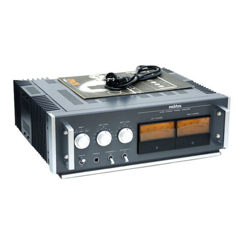
Studer Revox B740 Operating instructions

^QJOEM] R^OX
SERVICEANLEITUNG
SERVICE INSTRUCTIONS
i^TRUCTIONS DE SERVICE
-20 -10 0J
S./** 1
R^OX
B74a-srtAEO powsfl AMPuinen
IMVf C6FT UFVCL nGHT LtVEL L£TT CHAN'^ CHANNCL
'
!
;;'•••• !,-i
iJil.-- 'J1
n«Nb>
RCVO>
f
II

s'D'yisiaRs R^ox B740
SERVICEANLEITUNG
SERVICE INSTRUCTIONS
INSTRUCTIONS DE SERVICE

9mLDS)[£[^ R^OX B740 2
EINL.EITUNG
Das vorliegende Buch ist eine Neubearbei-
tung der Serviceanleitung fCir den Lei-
stungsverstarker B740.
Anderungen Oder Neuerungen wurden be-
rOcksichtigt.
Die Fgnktignsbeschreibung, die Abglei-
chenleitung sowie der Schemateil enthal-
ten samtiiche Angaben zu den A740- und
874O-Ausfbhrung0n.
INTRODUCTION
This book is arevised edition of the service
instructions for the power amplifier B740,
Modifications and innovations have been
considered.
The circuit description, the electrical adjust-
ments as well as schematic diagrams con-
tain all informations concerning the A740-
snd B740-versions.
INTRODUCTION
Ce livre st une nouvelle Edition de I’instruc-
tion deservicepourl'amplificateurde puis-
sance Revox B740.
Onatenu compte des modifications etdes
innovations.
La description des fonctions, I'ajustage el la
section schema contiennent lous les indi-
cations pour les vei^ions A740 et B74Q.
Prepared and edited by
STUDER -REVOX
TECHNICAL DOCUMENTATION
Althardsirasse 146
CH -8105 Regensdorf -Zurich
Copyright by Willi Studer
Printed in Switzerland
Order No. 18.194.1280
We reserve the right to make alterations as
technical progress may warrant

STOllISEin ReVoX B740 3
6. Schaltbilder 6/1 6. Diagrams 6/1 6, Schemas 6/1

siryissiMi R^/bx B740 SECTION 1/1
1. ALLGEMEINES
Osr hochwertige Stereo-Lsistungsverster-
ker 6740 wird wahrend der Fedigung und
in der Endkontrolle nach eng toierienen
Messdaten geprijft. Es ist deshalb unerl§ss-
iich, dass die entsprechenden Spezifika-
tionen kontrollieri werden, damit die ur-
sprtinglichen Eigenschaften des Cerates
vpll erhalten bleiben.
Achtung:
Bevor Service-Arbeiten am geflffneten Ver-
stSrker vorgenommen werden. ist unbe-
dingt darauf zu achten, dass die Siebkon-
denseloren entladen sind. Siehe Kap 2.2
Entladen der Siebkondensatoren,
1.1
Technische Oaten
Musikleietung:
300Wpro Kanal (4 Ohm)
beide Kanaie gleichzeiiig ausgesteuert
Ausgangsleistung:
(nach DIN 45500 bei 1kHz)
200W pro Kanal (4 Ohm)
125Wpro Kanal (80bm)
beide Kanale gleichzeitig ausgesteuert
Nannausgangsleistung:
(20 Hz ..20 kHz] Sinusleistung
l75Wpro Kanal (40hm)
100 Wpro Kanal (BOhm)
beide KanSle gleichzeitig ausgesteuert
DSmpfungslaktor:
grosser als 150 bei 1kHz |8 Ohm)
Frequeitzgang;
20 Hz... 20 kHz, +O/-0.75dB
Subsonic-Filter:
(schaltbar)
16 Hz -3dB. Steilheit 12 dB/Oktave
Harmonlsche Verzerrungen:
(20 Hz, „20 kHz)
kleiner als 0,1 %bei jedem Leistungspegel
bis Nennausgangsleistung
Transient Intermodulatione-Verzerrun-
gen (TID):
<0,03% bei 1kHz, lOOW/BOhm
Fremdspannungsabstand;
(Effektivweit)
grosser als 100 dB
bezogen auf Nennausgangsleistung
1. GENERAL
To ensure optimum performance within the
narrow tolerances which are sat for the ste-
reophonic high power amplifier Revox
B740, each unit must passa aeries of tightly
controlled production tests plus acareful
final inspection step. In order to maintain
the specified characteristics, it is essential
that all important performance data are
checked whenever an B740 comes to the
shop for servicing.
Important:
Before carrying out any service work on the
opened amplifier, discharge the filter ca-
pacitors as described in section 2.2 of this
manual.
1.1
Technical specifications
Continuous average sine wave power;
from 20 20 000 Hz at rated distortion:
175 Wper channel into 4ohms
100W per channel into 8ohms
(both channels simultaneously driven)
Damping factor;
minimum 150/1 kHz (8 ohms)
Frequency response:
20 ... 20 000 Hz. plus 0, minus 0,75 dB
Subsonic filter:
(switchable)
-3 dB at 16 Hz. roll off 12 dB/ octave
Total harrnonic distortion;
(20-20000 Hz)
less than 01%at any level up to rated out-
put
Transient intermodulation distortion
(TID);
<0.03 %at 1kHz, 100 W/8ohms
Signal to noise ratio:
unweighted (rms calibrated meier)
better than 100 dB
referred to rated output
1. GENERALITE5
En fin de montage, un contrble severe, aux
tolerances de mesure tr$s etroites, permet
eI'amplificateur de puissance st6reopho-
nique B740 de conserver sa quality si sss
caractenstiques techniques originales.
Important;
Avant toute interveniion sur I'amplificateur
ouvert, il esi imperatif de s'assurer de la d6-
charge des condensaieurs de filtrage, Voir
chapitre 2.2 dScharge des condensateurs
de filtrage.
1.1
Caract4ristiques techniques
Puissance musicale:
300Wpar canal (4ohms)
les deux canaux simultan^ment en service
Puissance de sortie:
(selon DIN 45500 e1kHz)
200 Wpar canal (4 ohms)
125W par canal (8 ohms)
les deux canaux simultanement en service
Puissance nominale:
(20 Hz ... 20 kHz) puissance sinusoTdale
175 Wpar canal (4ohms)
100W parcanal (8 ohms)
les deux canaux simultan^ment en service
Coefficient d'ornortissement:
sup^rieur e150 a1kHz (Sohms)
Reponse en frequence;
20 Hz,., 20kHz, -1-0/ -0.75 dB
Filtre infrasonore:
(cornmutable)
16 Hz -3dB, efficacite 12 dB/ octave
Oistorsion harmonique:
(20Hz.„ 20 kHz)
inf4rieur e0.1%. ^n’importe quel niveau
jusqu'a la puissance de sortie nominale
Distorsion d'intermodulation transi-
toire (TID):
<0,03 %e1kHz, 100 W/8ohms
Recul du bruit de fond:
(vateur effective)
sup6rieur^ 100 dB
par rapport 4la puissance de soriie nomi-
nale

s'iryi[S)[^ ni^ox B740 SECTION 1/2
UbersprechdSmpfung:
grosser als 75 dB bei 40 Hz
grosser als 70 dB bei lkHz
grosser als 60 dB bei 10 kHz
Eingfinge:
A: Cinch (Phono-Jack)
B: XLR-Buchse. weiblich (Cannon)
EingangswShler:
{3-stellig)
A-SUBSONIC FILTER
A-DIRECT
B- DIRECT
Eingangsimpedanz;
50k0hm
Eingangsempllndlichkeit:
IV fur Nennausgangsleistung (175W/
4Ohm)
Eingangsabschwdcher:
0... -27 dB, schaltbarinSdB-Stufen, fiirje-
den Kanal getrennt.
Genauigkeit 0,2 dB
LautsprecherausgSnge:
(scheltbar)
A: DIN-Anschlussbuchsen
B; Polklemmen (60 Ampere)
Kopfhbrerausgang:
Stereo-Jack euf der Frontplatte
Nennausgangsspannung 11,9 V
Ausgangslmipedanz; 100 Ohm
geaignat fur hoch- und niederohmige Kopf-
horer
AuSateuerungsanzeige:
2Peak Program Meter (Spitzenwertmes-
ser), beleuchtet
Anstiegszeit: <2,5 ms fur Anzeige -1dB
Ruckstellzeit;1,8 s/20dE
Skaia linear in dB, Bereich; -40...-h5dB
(OdB entsprechen 100 Wand 4Ohm Last)
Abmessungen der Instrumente:
95x73mm
Netzanschlu$$:
220 VAC
intern jmscheltbarlOO, 120, 140, 200,
220, 240 VAC
SicherungilOO.. 140V: BAT
200,.,240V:4AT
Leistungsaufnahma;
100„.800W
Crosstalk:
better ihan75dB at 40 Hz
better than 70 dB at 1kHz
better than 60 dB at 10 kHz
Inputs:
A: phono sockets
B: XLR type receptacles (cannon)
Input selector:
(3 positions)
A-SUBSONIC FILTER
A-DIRECT
B-DIRECT
Input impedance:
50 kohms
Input sensitivity:
IV for rated output (175 W/4 ohms)
Input attenuator:
0...-27dB, switchable for each channel
separately in 3dB steps.
Accuracy 0.2 dB
Loudspeaker outputs:
(switchable)
A: DIN speaker sockets
B; binding posts (60 amps)
Headphone output:
stereo jack on from panel
nominal output voltage: 11.9 V
output impedance: 100 ohms
Suitable for low and high impedance
phones.
Output level meters:
2peak program meters, internally illumi-
nated
response time <2.5 msec fora -1 dB indi-
cation
release time 1,8sec/20dB
linear dB scale, from -40 to +5dB
(0 dB equals 100 Winto 4 ohms)
meter dimensions: 95x73 mm
Electric current connections:
220 VAC
internally switchable forlOO, 120, 130, 200,
220, 240 V AC
Fuse: 100... 140V. 8A slow-blow
200... 240V; 4A slow-blow
Power consumption:
100...800W
Weight:
20kg/44lbs
Gewichti
20 kg
Recul de diaphonie:
sup6rieur ^75 dB S40 Hz
sup6rieura70dB^1kHz
supbrieur a60 dB ^10 kHz
Entries:
A, Cinch (Phono-Jack)
B: XLB prise feminine (cannon)
Seiecteur d’entree:
(3 positions)
A-SUBSONIC FILTER
A-DIRECT
B- DIRECT
Impedance d'entree:
50 kohms
Sensibility d'entrye:
IV pour la puissance de sortie nominale
(175W/4ohms)
Attynuateurs d'entryoi
0.„-27dB. par crans de 3dB, syparfes
pour chaque canal
precision 0.2 dB
Sorties hsut-parleur:
(commutables)
A: prises DIN
B; bornes (60 amperes)
Sortie casque:
Jack stereo sur Is psnnesu frontal
tension de sortie riominale: 11.9 V
impedance de sortie: 100 ohms
pour casque haute dbassa impedance
Indicateurs de modulation:
2Peak Program Meters (indicateurde va-
leur de pointe), edaires
temps de montye: <2,5ms pour I'mdica-
tion -IdB
temps de descents, 1,8 ms /20 dB
Schelle linSaire en dB: -40..,-l-5dB
(OdB correspondant e100W avec une
charge de 4ohms)
dimensions des cadrans: 95 x73 mm
Raccordement secteur:
220 V AC
(commutation interne pour lOO, 120, 140,
200, 220, 240 VAC
Fusible: 100... 140V: 8 Aretard^
200„.240V:4Aretardy
Consommation:
100„.80DW
Folds:
20 kg

R^/bx B740 SECTION 1/3
1.2
Abmessungen
[Oline Anschlusssiecker auf derRiickseite)
[BxHxTl 450x^51 x357 mm
1.2
Dimensions
(without connecting plugs on rear panel)
(wxhxdi 450x151 X357 mm
(17.71 X5.94 X14.05 irwhes)
1,2
Dimensions
(La place pour les connecteurs XLR sur ie
panneau amere non inclus)
(I Xh X p) 450x 151 x357 mm
397
AFrontserte AFront panel A1^nneau frontal
©Netzschalter POWER ®Electrical POWER switch ©Intemjpteur secteur POWER
Kopihorerbuchse PHONES @Head-PHONES jack ®Prise casque PHONES
Lautsprechergruppen-Sctialtec
SPEAKERS A®Output selector
SPEAKERS A@Commutateur haut-parleur
SPEAKERS A
Lautsprechergfuppen-Schalter
SPEAKERS B@Output selector
SPEAKERS B@Comrrulateur haut-parleur
SPEAKERS B
®Eingangswahlschatler INPUT ®INPUT selector ©Selecteur d'entree INPUT
F^gelregler linker Kanal
LEF LEVEL ®Input attenuator
LEF LEVEL ®Reglage du niveau canal gauche
LEF LEVEL
®Pegetregle; rechter Kanal
RIGHT LEVEL ©Input attenuator
RIGHT LEVEL ©Reglage du niveau canal droit
BIGHT LEVEL
Modulometer linker Kanal
L£F CHANNEL Fteak program meter
LEF CHANNEL McHdulometre canal gauche
LEF CHANNEL
®Modulometer rechter Kanal
RIGHT CHANNEL E^ak program meter
RIGHT CHANNEL ®Modulom&tre canal droit
RIGHT CHANNEL

B740 SECTION 1/4
BRifckseite BRear panel BPanneau arri^re
EingSnge INPUTS INPUTS Entries INPUTS
CINCH-Eingangsbjchse A,
rechter Kanal
Phono socket A, right channel ®Prise d'entr^ CINCH A,
carral droit
®CINCH-Eingangsbiichse A.
linker Kanal
Phono socket A, left channel ®Prise denu^ CINCH A,
canal gauche
@CANNON-Eingang B. rechter Kanal ®XUI-type receptacle B, right channel ®Prise d’entr^e CANNON B. canal
droit
@CANNON-E ingang B. linker Kanal @XLR-tvpe receptacle B. left channel Prise d'entree CANNON B. caral
gauche
Ausgange SPEAKERS Sorties SPEAKERS Outputs to SPEAKERS
DIN -Lautsprecherbuchse,
SPEAKERS A. rechter Kanal
DIN-sccket SPEAKERS A.
right channel
Prise haut-parleur DIN
SPEAKERS A, canal droit
DIN-Lautsprecherbjchse,
SPEAKERS Alinker Kanal ®DIN-socket SPEAKERS A,
left charnel ®Prise haiit-parleur DiN
SPEAKERS A, canal gauche
Laiflsprecher-Polklemmen,
SPEAKERS B. rechter Kanal
Binding posts SPEAKERS B.
right channel ®Bomes haut-parleur
SPEAKERS B. canal droit
Laulsprecher-Polklemmen.
SPEAKERS B. linker Kanal
Binding posts SPEAKERS B,
left charnel ®Bernes haut-parleur
SPEAKERS B. canal gauche
Netzsicherung ®Fuse ®Fusible secteur
Netanschluss @AC inlet plug @Raccordemenl secteur

STPOERi REVbX B740 SECTION 2/1
Kurzschluss (Entladen siehe 22)
Short circuit (Discharge see 2.2)
Court Circuit (DScharge voir 2.2)
2. AUSBAU
Achtung:
Bevor am geCtfnetenVerstarkerAusbauar-
beitenausgefuhrtwerdenistzuijberprufen,
ob die Siebkondensatoren entladen sind.
2.1
Entfernen des Oberert Deckbleches
-Verstarker vom Netz trennen
-2Schrauben [21] auf der RDckseite I6sen
-Deckblech hinten anheben und ausfah-
ren.
2.2
Entladen der Siebkondensatoten
'Deckblech entfernen.
-Verstarker ausschalten (Netzstecker Zie-
hen),
Achtung:
Die Sammelschienen der Siebkondensato-
ren durfen nicht kurzgeschlossen werden.
-Auf Netzteil 1.068.734 mil Schraubenzie-
her zwischen TP5 und -M2 Vsofort kurz-
sghliessen (siehe Fig. 2.1.1). Es ist dabei
ein merklicher Stoss im Schraubenzieher
zu verzeichnen.
Bei belastetem Verslarker entladen sich die
Kondensatoren Oder die Last.
2. DISMANTLING
Important:
Before carrying out any service work Oh the
Opened amplifier, discharge the filter ca-
pacitors as described in section 2,2 of this
manual.
2.1
Removal of top cover
-Disconnect amplifier from the electric
current supply.
-Remove two screws [21] on the back of
the unit.
-Raise top cover atthe rear and removeto-
wards the rear
2.2
Discharging the filter capacitors
-Remove top cover as per section 2.1.
-Amplifier must be disconnected from the
electric current supply.
Important:
Do not try to discharge Vie capacitors by
simply short-circuiting the bus-bars.
-Create an electrical connection (using a
screwdriver) between TP5 and +12Vin
the power supply 1.068.734 as indicated
in figure 2,1.1 ,After having made this con-
nection, adistinct vibration (mechanical
shock) will be felt through the screwdri-
ver
With aload connected to the amplifier, the
capacitors will discharge through the load.
2. DEMONTAGE
Attention;
Avant le demontage de I'amplificateur ou-
vert s' assurer de la d^charge desconden-
sateurs de filtrage.
2.1
Depose de la plaque de recouvrement
supdrieure
-Retirer de prise secteur.
-Devissar 2vis [21] sur le c6t6,
-Souleverettirervers I'arridre la plaque de
recouvrement.
2.2
D6charge des condensateurs de fil-
trage
-Enlever la plaque de recouvrement.
-Ddclencher I’amplificateur [retirer de pri-
se secteur).
Important:
Les barres de contact des condensateurs
ne doivent jamais stre an court-circuit.
-AI'aide d'un tournevis, etablir un contact
entre TPS et l12V (voir fig. 2.1.1); au mo-
ment du court-circuit, il se produira une
secousse sur le tournevis.
Si des haut-parleurssont raccord^s S I’am-
plificateur, ia d^charge des condensateurs
se fera au travers d'une resistance.

ST[y7[^X(R R^OX B740 SECTION 2/2
Fig, 2.1.3 Fig. 2.1,4 Fig. 2.1,5
2.3
Endstufe ausbauen
-Oberes Deckblech entfernen (siehe 2.1.),
-2Schrauben [22] vorne ISsen,
-2Schrauben [23] ander Riickseile IGsen.
-Kuhikdrper rnit aufgebauter Endstufe
kann zur Uberprufung nach untan ge-
klappt warden
2.3
Removal of power stages
-Remove top cover as per section 2.1.
-Remove two screws [22] at the front,
-Remove two screws [23] at the rear,
-The heat sink, complete with output tran-
sistors, may now be hinged downwards
to gain access for testing.
2.3
OemoiTtage de retage de puissance
-Enlever la plaque derecouvrement supS-
rieure (voir 2,1).
-D6visser 2vis [22] devant,
-D^visser 2vis [23] II'arri^re.
-Fbur le Controls, Is radiateur et le circuit
de puissance peuvent Stre abaiss^s sur le
C6t6.
2.4
Frontplatte ausbauen
-3Schalterknopfe nach vorne abziehen,
-Kippschaltsr nach unten stellen.
-Vordere Fussleiste entfernen, 2Schrau-
ben [24] von der Unterseite losen.
4Schrauben [25] auf der Frontplatte 10-
sen. Frontplatte mittels Griffen vorsichtig
nach vorne abziehen.
2.5
Lampe In Modulometer auswechsein
-Frontplatte ausbauen (siehe 2.4).
-4Schrauben [26] losen,
-instrumente mit Platte ausbauen, ROck-
seitig angebrachler Printstecker auszie-
hen,
-Die Lampen auf der dahinterliegenden
Platte Sind nun zugSnglich.
AnmerKung:
Die Helligkeit der beiden Lampen ist vor
dem Zusammenbau der Instrumente auf
identische Leuchtstarke zu prufen.
2.4
Removal of front panel
-Pull knobs from the three toggle swit-
ches.
-Bring switches into their OFF position,
-Remove front toe rail. Remove 2screws
[24] on the bottom.
-Remove four screws [25] on the from
pennei. Take holdof the two handles and
carefully pull the front panel forward and
away from the amplifier.
2.5
Lamp replacement for rneterillumina-
tion
-Remove front panel as per section 2.4.
-Remove four screws [26].
-Remove meters with mounting plate.
Remove the plug-in connector on the
back of the meters.
-Access to the lamps on the olate located
Just behind is now possible.
Note:
Before installing newlamps.checkthem for
identical brightness to ensure equal illumi-
nation of both meters.
2.4
Depose du panneau frontal
-Tirer vers I'avant les 3boutons,
-Les commuteteursdoiventregarder vers
le bas.
-Enlever les listes d'appuis event.
D6visser 2vis [24] sur le c6t6 inferieur.
D^isser 4 vis [25] sur le panneau frontal,
Retirer avec precaution vers I'avant le
panneau frontal avec ses poign^es.
2.5
Echange des lampea des modulo-
metres
-Retirer le panneau frontal (voir 2.4).
-DSvisser 4vis [26].
-Ddmonter les instruments avec le circuit.
Sur le cflt4 arriSre retirer les prises.
-Les lampes derri^re la plaquette sont ain-
si accessibles.
Remarque:
Verifier que la luminosity des lampes soit
ygale.

STOElEaffi R^OX B740 SECTION 2/3
2.6
N6tz-Sicherung auswechsein
-Netzstecker ziehen,
-Bajonettverschluss auf Riickwand off-
nen.
-Defekte Sicherung auswechseln.
2.7
Ndt2$pannungsw§hler einstellen
-2Schrauben [27] auf der RQckseite IGsen
und Abdeckung entfernen.
-Erfordertiche Netzspsnnung mit Span-
nungswShler einstellen.
2.8
Netrteil-Sicherungen wechsein
-Oberes Deckblech ausbauen (siehe 2.1).
-Defekte Netzteil-Sich&rungan auf dem
Nefeteilprint auswechseln.
2.9
Endstufen- und Vorverstdrkerprint
ausbauen
-Endstufe ausbauen (siehe 2.3).
-Samtliche Steckverbindungen auf den
beiden Prints aussiehen.
-Treiber-Kuhlkdrper ausbauen, 2Schrau-
ben an der Kuhlrippenseite Idsen, NTC-
Anschlusse ausder Steclwerbindung zie-
hen. KOhlkflrper mit monlierten Transisto-
ren aus den Steckverbindungen des End-
siufenprinis ziehen.
-2Schrauben auf VorverstSrkerprint Id-
sen. Vorverslarkerprint nach vorne ab-
nehmen.
-7Schrauben auf Endverstarkerprint vor-
sichtig senkrecht nach oben abheben.
2.6
Replacement of main fuaa
-Disconnect amplifier from the electric
current supply,
-Remove twist lock cap from the fuse hol-
der.
-Replace defective fuse.
2.7
Adjustment of voltage selector
-Remove two screws [27] on the ampli-
fier's back and lift off the cover plate,
-Adjust voltage selector to required set-
ting.
2.8
Replacement of power supply fuses
-Disconnect amplifier from electrical cur-
rent supply
-Remove top plate as per section 2,1
,
-Locate defective fuse on the power sup-
ply board and replace.
2.9
Removal of output stages and pream-
plifier boards
-Remove output stages with their heat
sinks as per section 2.3.
-Disconnect all plug-in wire connections
from both printed wire circuits.
Remove heatsink of driver stages, Undo
two screws at the side of the cooling fins,
Unplug connections of the NTC-resistor.
Pull the heat sinks with their transistors
from the plug-in connections in the
printed circuit board.
-Remove two screws from the preampli-
fier circuit board. Take preamplifier
boardstowardsthefrontout of tine ampli-
fier,
-Remove seven screws from the power
amplifier board and carefully lift the
power amplifier vertically out of the unit.
2.6
Echange du fusible secteur
-Retirer la prise du secteur,
-Ouvrir la bouchon ^balonnstte kTarrifere
de I'appareil.
-Changer le fusible d^fecfueux,
2.7
Adaptatiort de la tension secteur
-D6visser 2vis [27] &I'erriSre et Qter le
couvercle.
-Mettre le s6lecteur de tension sur la posi-
tion correspondam Sla tension secteur,
2.8
Echange des fusibles d'alimentation
-Enlever la plaque de recouvrement sup6-
rieure (voir 2,1),
-Changer le fusible dbfectueux du circuit
d’alimentation
2.9
P^montage du pr^amplificateur et de
I'dtage de puissance
-D6monter I’btage de puissance (voir 2,3).
-Retirer les diff^rentes prises des deux cir-
cuits.
-Dbmonter les radiateurs. Ddvisser 2vis
sur la radiateur, Retirer de la prise de rac-
cordement les connexions NTC, Retirer
le radiateur avec les transistors de puis-
sance des prises de raccordement du cir-
cuit de puissance.
-Dbvisser 2vis sur le circuit de puissance.
Retirer par I'avanl le prbamplificateur
-D^visser 7vis sur le circuit de puissance.
Retirervers le hautavec precaution le cir-
cuit de puissance.

siroiKsei^ R^ox B740 SECTION 2/4
Fig. 2.1.7
Anmerkung:
Beim Einbau darauf achten, dass die An-
schlOsse des Transistors 09 (auf dem Kiihl-
gehSuse) in der ruckwSrtigen Stackverbin-
dung auf dem Endstufenprint einwandfrei
kontaktieren,
2.10
Netzteilprint ausbauen
-Oberes Deckblech entfernen (Kap, 2,1),
-Die acht Transformatorkabel losen.
-Auf Siebkondensaioran-Sammelschis-
nen (-i-. -) die roten und blauen Anschlus-
se Idsen.
-3Sleckverbindungen auf dem Netzteil-
printausziehen.
-4Schrauben losen.
-Netzteilprint herausheben,
2.11
Instrumentenprint ausbauen
-Oberes Deckblech entfernen (Kap. 2.1).
-1Steckverbindung ausziehen,
-Von Unterseite 2Schrauben [28J Ibsen,
2.12
Siebkondensator ausbauen
-Oberes Deckblech entfernen (Kap 21).
-Sammelschlenen Ibsen und ausbauen.
-Von der GerSte-Unterseite 6Schrauben
129] Ibsen.
-Zentralbefestigung des entsprechenden
defekten Siebkondensators Ibsen und
neuen Kondensator einsetzen.
2.13
Drehschalter ausbauen
-Frontpiatte ausbauen (slehe 2.4).
-2Befestigungsschrauben auf entSprS-
chendem Schalter Ibsen,
Note:
When inserting the power amplifier board,
make surethatthe connections oftransistor
Q9 (on the heat sink) make good electrical
contact with the plug-in connections on the
power amplifier board.
2.10
Replacement of power supply
-Remove top cover as per section 2,1,
-Disconnect the eight transformer wires.
-Disconnect the red and blue wires from
the bus bars on the filter capacitors,
-Disconnect three plug-in connections
from the power supply board,
-Remove four screws,
-Lift power supply out of the unit.
2.11
Removal of meter amplifier
-Remove top cover as per section 2.1.
-Disconnect one plug-in connection.
-Remove two screws [28] on the bottom.
2.12.
Removal of filter capacitor
-Remove top cover as per section 2,1.
-Disconnect and remove bus bers.
-Remove six screws [29) on the bottom of
the unit.
-Undo central mounting nut of the capaci-
tor which has to be replaced.
2.13
Removal of rotary switches
-Remove front panel (see section 2.4).
-Remove two mounting sCrewS Of rotary
switch.
Remarque:
Lors de la remise en place du circuit, veiller
h ce que les connexions du transistor Q9 fi-
xbsurleradiateur.entrentlibrementdansle
connecteurcorrespondantducircuitimpri-
mb.
2.10
D^montage du circuit d'alimentation
-Dfivisser lesS connexions du transforma-
teur.
-Dbconnecter les fils rouges et bleus des
barres de contact des condensateurs de
filtrage.
”Enlever les 3prises du circuit d'alimenta-
tion
-D6visser4 vis,
-Eniever par le haut la circuit d'alimenta-
tion.
2.11
D^montage du circuit de mesure
-Enlever la prise du circuit.
-Dbvisser2 vis [28] en dessous de I'appa-
reil.
2.12
D4montage des condensateurs
-D^visser el enlever les barres de contact.
-Dbvisser6vis(29] en dessous de i'appa-
reil.
-Dbvisser la vis centrale du condensateur
dbfectueux. Remonter un nouveau con-
densateur.
2.13
^montage des commutateurs
-Enlever le panneau frontal (voir 2.4).
-D^visser les 2vis de fixation du commu-
tateur correspondant.

B740
EinyiQISI^ RI^^X SECTION 3/1
tf^T iilPljT ifVtL HI SLMONie ^ASEUNUR PmR PiniHTi9R
Fig, 3.1
3. FUNKT10NSBESCHREIBUNG
3.1
Beschreibung des Blocksclialtbildes
Mit dem Eingangswahlschalter wird in
Stellung (A SUBSONIC FI) ein Subsonic-Fil-
ter geschaltet. Dieses Filter erzielteine Star-
ke Pegelabsenkung bei Signaler unter
20 Hz.
Auf den Schalterstellungen (A-DIRECTi
und (B-DiRECT) werden die EingSnge A
und B direkt an den Verstarker geschaltei.
Die Ftegelregler ermdglicben die Pegelre-
gulierung des linker sowie des rechten Ka-
nals in 3dB-Stufen von 0...-27dB, Auf
Stellung 0dB und bei 1VEmgangssignal er-
gibt sicb eine Ausgangsleistung von 175 W
an 4Ohm Impedanz,
Nach der 7,5dB-VBrstarkung im Vorver-
starker wird dss Signal Ober das Subsonic-
Filter und das phasenlineare Tiefpassfilter
(75 kHz) an den Eingang der Leistungsend-
stufe gebrecht. Diese Endstufe besitzt eine
fest eingestsllte VerstSrkung von 2l dB.
Eine aufwendige Begrenzerschaltung ver-
hindert den Betrieb der Endtransistoren
ausserhalb des erlaubten Bereiches der
Verlustleistungshvperbel der Transistoren.
Das Ausgangssignal der Leistungsendstufe
ist an den Buchsen auf der ROckseite sowie
liber einen Abschwbcheran die Kopfhbrer-
buchse auf der Frontplatte herausgefiihrt.
3. CIRCUIT DESCRIPTION
3.1
Deecription of block diagram
The input selector permits the insertion of a
high-pass filter when selecting the position
'A SUBSONIC FI”. This filter attenuates all
frepuencies below 20 Hz. In the switch po-
sitions A-DIRECT and B-DIRECT the inputs
Aor Bare connected directly to thefirst am-
plifier stage.
The input attenuators permit accurate level
adjustments for each channel in steps of
3dB over the range frorn 0to -27 dB. In po-
sition OdB and with asignal input of 1volt,
the amplifier will deliver 175watts into
4ohms load.
Alter 7.5 dB of amplification in the pream-
plifier. the signal passes the subsonic filter,
followed by aphase linear tow-pass
(75 kHz) from where it reaches the input of
the power amplifier. The power amplifier
has afixed amplification factor of 21 dB.
An elaborate control circuit protects the
output transistors from being operated
beyond their maximum power dissipation
rating. From the powerstages the signal ap-
pears at the output sockets on the rear and,
via suitable attenuation networks, at the
headphone jacks on the front panel.
3. DESCRIPTION DES FONCTIONS
3.1
Explication du schema-bloc
En position (A SUBSONIC Fli du s^lecteur
d'sntrees sont commutbes aun filtre infra-
sonorequi attbnuefortement las signaux de
frequence infbrieure b20 Hz.
Les positions <A-DIRECT) et iB-DIRECTi
commuientdirectementlesentreesAetBb
I'amplificateur,
Les rbglages de niveau permertent I'adap-
tation des canaux gauche et droit par crans
de 3dB, de 0... -27dB. En position OdB
avec un signal d’entrbe de 1V. la puissance
ds sortie est de 175 Wpour une impedance
de4ohms.
Sortant du prbamplificateur avec un gain
de 7,5 dB la signal estamenb bI’blage de
puissance par un filtre infrasonore suivi
d’un filtre passe-bas (75 kHz). Cet btage de
puissance aun gain fixe de 21 dB,
La mise en oeuvre d'un circuit limiteur pro-
tege les transistors de puissance centre un
dbpassementdeslimitesde dissipation, Le
signal de sortie est disponible sur les bor-
nes du panneau arnere etvia un attenuateur
sur les prises casque du panneau avant

STQJ)!Sl[£[!!] R^OX B740 SECTION 3/2
Der Betrieb des Stereo-Leislungsverstar-
kers B740 wird durch zusatzliche Schulz-
schaltungen uberwacht.
Temperaturschutz:
Erste Temperatufschwell©
Abschaltung derstabilisiertenSpeisespan-
nung infolge ubermassigerErwarmung der
seitlichen KCihlkdrper der LeistungsendStu-
fen sowte des Netzieiles.
Drsi NTC-Widerstande fuhlen auf den er-
wahnten Kuhikdrpern die Temperatur Stellt
sich auf einem seitlichen Kuhikdrper eine
Temperatur von 90°C Oder auf dem Kuhl-
kOrper des Netzteils eine Temperatur von
120°C ein, so schaltet der Uberwachungs-
kreis die stabilisienen Speisespannungen
(±62,5 V) ab. Die Lautsprecherausgange
werden spannungsfrei, Durch die Leislungs
transisioren fliessen keine Rghestrome
mehr und dadurch erfolgt ein schnelles Ab-
kiihlen des Verstarkers,
Bei Erreichen der ersten Temperatur-
schwelle schaltet die Instrumentenbe-
leuchtung ab.
Zweite Temperaturschwelle
Die Crowbarschaltung des Verstarkers
wird bei einem Weiteranstieg derTempera-
tur auf 12D°C auf den seitlichen Kuhikdr-
pern Oder 150°C auf dem Netzteil-Kuhikor-
per aktiv, Die Oberwachungsschallung
startet einen Thyristor, welcher die Sieb-
kondensatorendesLeistungsneateilskurz-
schliesst und somit die Primarsicherung
zum Schmelzen bringt
Lautspreche^chutz;
Trin am Lauisprecherausgang eine Span-
nung von <3 Hz und >8V wahrend 1...
1,5s auf, so wird ebenfalls die Crowbar-
Schaltung aktiviert Somit werden die an-
geschlossenen Laufsprecher-Systeme ge-
gen Uberbelastung geschutzt.
Modulometer:
im Instrumentenverstarker wird das Aus-
gangssignal gleichgerichtet verstarkt und
logarithmiert dem Aussieuerungsinstru-
ment zugefuhrt.
3.2
Beschreibung d«r Schutzschaltungen
Je ein NTC-Widerstand ist auf dem Kuhl-
korper der Leistungsendstufe angebracht.
Die Anschlusse sind Gber den VorversiSr-
kerprint1,068,733geschlauftundfuhrenzu
der Sohutzschaltung auf dem Leistungs-
netzteil1.068.734.
Vital peiormance characteristics of the
amplifier B740 are being monitored by ad-
ditional protection circuits in order to pre-
vent catastrophic failure,
Protection against overheating:
First temperature threshold
De-activation of the stabilized supply volt-
ages as aresult of excessive temperature
rise on Uie heatsinks of the power transis-
tors and in the power supply.
Three NTC-resistors are mounted on the
mentioned heatsinks. Should the tempera-
ture of the output stages rise to 9CPC or
120°C In the power supply, the stabilized
supply voltages (-1- 62,5 V) become de-acti-
vated and there will be no longer any signal
appearing at the outputs. The quiescent
current through the output transistors gels
turned off, thus cooling will be rapid. When
this first temperature threshold is reached,
the meter illumination will extinguish.
Second temperature threshold
If frie temperature continues to rise to
120° Con the output transistor heat sinks, or
to 150°C in the power supply, the crowbar
circuit becomes activated. That circuit cau-
ses athyristor to become conductive,
thereby short-circuiting the filter capaci-
tors of the power supply with the effect the
amplifier's main fuse blows.
Loudapeakdr protection
If asignal condition of <3 Hz and >8V
develops across the speaker output for a
period of 11.5 sec, then the crowbar cir-
cuit will also become activated. The loud-
speakers connected to the amplifier are so
protected from dangerous DC overload.
Peak program meter
In the meter amplifier the output signal is
rectified and converted into alinear decibel
ratio by logarithmic amplification to drive
the peak program meter.
3.2
Description of fail-safe circuits
ANTC-resistor is mounted on each of the
two heat sinks of the output transistors.
Their connections are looped via the
preamplifier 1.068.733from where they are
wired to the protection circuit on the power
supply board 1.068.734, The NTC-resiSlor
Lampiificateur de puissance stereophoni-
que B740 est 6quip4 de plusieurs protec-
tions,
Protection thermique
ter seuil de temperature
Lampiificateur est mis automatiquement
hors-service en cas de temperature exces-
sive des radiateufs des transistors finals ou
de I'alimentation de puissance.
La temperature est mesut4e partrois resi-
stances NTCsituees sur les radiateurs men-
tionnes ei-dessus. Si les temperatures de
ces derniers dSpassent 90°C (alimenta-
tion). un dispositif d4denche la tension
d’alimentation (±62,5 V) et les sorties haut-
parieurs som coupdes. Le couram de repos
ne circulant plus 4Iravers les transistors,
ceux-ci se refroidissent rapidement Au
premier seuil de temperature les modulo-
metres s'eteignent-
2eme seuil de temperature
Si les temperatures continuent d'augmen-
ler et atteignent respectivement 120° Cet
150°C, un circuit crowbar entre en action,
Ce dernier est 6quip6 d’un thyristor qui est
commandeparlecircuitdemesuredetem-
p4rature et qui s’allume lors du d4passe-
ment du 24me seuil, court-circuitant ainsi
I'alimentation, ce qui provoque la destruc-
tion du fusible secteur et la mise hors-servl-
ce de ramplificateur.
Protection des haut-patfeurs
Si un signal de frequence inf6rieure 43Hz
et d'amplitude sup4rieure 48V apparait
aux sorties haut-parleurs, le circuitcrowbar
entre en action (voir chapitre pr4c6dant).
Les haut-parleurssontainsiprot4g4s centre
les surcharges continues,
Modulometres
Le signal de sortie est dgalement envoyd au
circuit demesure qui le redresse etl'ampli-
fie Ipgarithmiquement pour la commande
des moduiometres.
3.2
Description des circuite de protection
Une resistance NTC, mont6e sur chacun
des radiateurs des transistors de puissan-
ce. est connectee via le pr4amplificateur
1,068.633 au dispositif de prelection situ4
sur le circuit de I’alimentation de puissance
1,068,734,

avyisisffi R^ox B740 SECTION 3/3
Der NTC-Widerstand auf dem Kijhikdrper
des Netzteils selbst ist ebenfalls an die
Schutzschaltung angeschlossen.
Diese Schucschaltung ist auf 2Tempera-
turschwellen ausgelsgt,
1Ansprechschwelle:
90®C auf den Leistungsendstufen Oder
120°C auf dem Net2leil.
Bei den erw^hinten GehSusetenperaturen
Sink! der Widerstandswert der NTC-Wider-
stande, so dass sich die Spannung an den
konstenten Spennungsteilerwiderstanden
(R11, R12, R13) erhdht, Uberschreitet die
Spannung am Anschluss 6 von ICl den
festen Schwellenwert am Anschluss 6vOn
ICl (ca. +6V),sokippiderAusgangspunki
7auf negatives Potential (ca. -12 V). Transi-
stor Q3 bringi positives Potential an die
Transistoren Q5 und Q10, welche die sta-
bilisierten Speisespannungen -62,5 Vund
(62,5Vabschalten.
2. Ansprechschwelle'
120“C auf den Leistungsendstufen Oder
150*C auf dem Netzteil.
Bei Weiteranstieg der Temperaturen steigt
die Spannung Liber den Widerstanden R11,
R12 brw. R13 ebenfalls weiter an, Am An-
schluss 2von 1C 1ist ein hdhererSchwellen-
wert (ca. -i-7,7V) fsst eingestsllt Am Aus-
gangsanschluss 1stellt sich positive Span-
nung [ca. -M2V) ein, wenn die Elngangs-
spannung am Punfct 3 den Schwellenwert
uberschreitet, Die Transistoren Q1 und Q4
schalten. C6 wird geladen, der Diac D21
(6,.,SV) starlet den Thyristor SCRI und
dieser schliesst die Siebkondensatoren
kurz. Die Pnmarsicherung schmilzt und
trennt den Verstarker vom Netz.
Dyrch Enfernen des Verbindungssteckers
zwischen R35 und dem SCRI wird die Feh-
lersuche an deraktivlerten Crowbar-Schal-
tung ermdglicht
Lautsprecher-Schutzscheitung:
Die Lautsprecherausgange warden bei Fre-
guenzen kleiner ca. 3 Hz und grdsser ±8 V
spannungsfrei. Die Abschaltung erfolgt
ubar die bereits erwahnte Crowbar-Schal-
tung (Schmelzen der Primarsicherung).
Ober ein Tiefpassfilter und einen Dioden-
und Spannungsteiler-Schaltkrais addiert
sich der positive Gleichspannungs-Anteil
on the heat sink of the power supply is also
connected to the protection circuit.
This protection circuit is designed to re-
spond to the following two temperature
thresholds.
1threshold
90* Con the powertransistor heatsinks or
120° Cin the power supply.
At the above mentioned heat sink tempera-
tures, the resistance of the NTC-resistors
falls off to avalue which causes the voltage
drop across R11, R12and R13 to rise until the
voltage on pin 6of IC 1exceeds the fixed po-
tential on pin 5of ICl (4-6 Vapprox) and
pin 7/iCi flips to anegative potential
(-12Vapprox.).TransistorQ3 feeds a posi-
tive potential to Q5 and Q10, and they effect
the turning off of the stabilized -62,5 Vand
+62.5 V.
2, threshold
120° Cat the heat sinks of the power tran-
sistors or150°C in the power supply.
With afurther increase of the heat sink tem-
perature. the voltages across R11. R12 and
R13 respectively will continue to rise, At pin
2of 1C 1the threshold voltage is set to
+7 7V approx. As soon as this potential is
exceeded on pin 2, then pin 1/ ICl flips to
positive (+12 Vapprox.), the transistors Q1
and 04 become conductive, causing C6 to
get charged and the Diac D21 fires the thy-
ristor SCRI. which causes ashort-circuit
across the filter capacitors. The amplifier's
main fuse blows, thereby disconnecting the
amplifier from the electric current supply.
Removal of the interconnecting plug be-
tween R35 and SCRI makes trouble-shoot-
ing in the activated crowbar circuit possi-
ble.
Loudspeaker protection
If asignal condition develops across the
loudspeakerterminals. which corresponds
to a frequency of less than 3Hz with an am^
plitude in excess of ±8V the amplifier will
be de-activated by ttie already described
crowbar circuit (amplifier's main fuse
blows).
Via alow-pass filter and adiode and volt-
age dividing network, the positive and
negative DC components are building up
La resistance NTC moni^e sur la radiateur
de lalimentation de puissance est egale-
ment conneci6e au dispositif de protection.
Ce dispositf est congu pour les deux seuils
de temperature suivants:
ler seuil de temperature:
90° Caux transistors da puissance ou
120°Cet’alimentation,
Des quels temperature des radiateurs aug-
manta, la valeur des resistances NTC dimi-
nue, ce qui provoque une augmentation de
la tension aux bornes des resistances R11,
Rl2 et R13, Sur le point 5de IC 1. le seuil de
tension est fixe a+6Vsnv. Aussitflt que sur
le point 6 de IC 1ce seuil est depasse, (tem-
perature des radiateurs depassant les va-
leurs indiquees ci-dessus) il se produit un
basculement du point 7de IC 1qui pesse e
env. -12 V. Le transistor Q2allume lalampe
OVERLOAD, Le transistor Q3 donne un po-
lentiel positif sur 05 et 010, ce qui coupe
ralimentation stabilisee +62.5V et
-62,5V.
2eme seuil de temperature;
120®C aux transistors de puissance ou
150°C eI’alimentatiOn
Si la temperature continue eaugmenter, la
tensin aux bornes de Rll, R12 et R13 conti-
nue egalement d'augmenter Au point 2de
IC 1, le seuil estfixSe 7,7 Venv. Aussiifttque
latensionau point 3de IC Idepassece seuil
(lemperatuf© des radiateurs depassant les
valeurs in diqu§es ci-dessus), il se produit
un basculement du point 1de IC 1qui passe
aenv, +12 VLes transistors Ql etQ4com-
mencent econduire, ce qui charge C6 etal-
lume lethvristor SCRI par I'interm^diairedu
diac D21, court-circuitant ainsi les conden-
sateurs de filtrage. Les fusibles secteurs
sent ainsi d^truits et I’appareil eSt isol6 du
secteuf,
En retirant le pont entre R36 et SCR1, il de-
vient possible de chercher une panne dans
le circuit crowbar.
Protection des haut-parleurs
Si un signal dune frequence infehsure 6
3Hz et d’une amplitude sup^rieure ^+8V
apparsit aux sorties haut-parleurs, I'amplifi-
cateur est automatiquement d§clench§:
ceci par riniermddiaire du circuit crowbar
qui detruit le fusible secteur.
Via un (litre passe-bas, un diviseur de ten-
sion et un pent de diodes, les altemances
negatives sent envoy^es sur le point 9de

s*m[sisi^ reVqx B740 SECTION 3/4
am Anschluss 12 vom 1C 1und der negative
Gleichspannungs-Anteil am Anschluss 9
vom 1C 1. Die Spannungswerte an den Re-
ferenz-Eingangen sind durgh fixe Span-
nungsteiler festgehallen (ca. ±3V), Treten
GleichspannungenausserhalbdieserRefe-
renz-Werte an den Anschlussen 9bzw. 12
auf, so 1st am Ausgang eine positive Soan-
nung (ca. -M2V) vorhanden, Diese Span-
nung steuert die Crowbar-Schaltung und
die Nelzsicherung sdhmilzt. Die Zeitkon-
stame von 1.,1,5s des Gliedes R33/C6
verhindert, dass die Crowbar-Schaltung
auf nur kurzzeitig aber noch night gefahrli-
che Gleichspannungsstdsse anspricht.
3.3
Beechreibung des Inetrumentenvef-
starkera
Das Signal am Eingang gelangt auf die
Doppelweg-Gleichrichtung und verstarkt
die Haibwellen um den Faktor2,7 R13 und
C3 im linken Kanal, R51 und C4 im rechten
Kanal bestimmen die Ansprechieit der In-
strumente, Rl4, fil5, C3 bzw. R52, R53, C4
bestimmen die Rucklaufzeit der Instrumen-
te, Mit Rl8 (R56) kann die Linearitat der
Rucklaufzeit beeinflusst warden.
Der VerstSrker mit D9 [Dl9) im Gegen-
kopplungszweig logarithmiert das vom
Gleichrichter kommende Signal. Fur Refe-
renzanzBige ist die Ausgangsspannung am
Anschluss 12 vom 1C 1(Anschluss 10, 1C 2)
gieich null Volt, well der durch R29 (R67)
abfiiessende Strom gieich gross istwie der,
durch die Referenzspannung erzeugte, zu-
fliessende Strom durch R30 (R68). Wird
der Signalpegel reduziert, so verkleiner:
sich der durch R30 (R68) abfiiessende
Strom. Die Ausgangsspannung. am An-
schluss12 vom 1C 1(10, 1C 2) ist proportional
der Stromdifferenz,
Die mechanische Nullstellung des Mess-
werkes liegt bei Referenzanzeige. Fur Ein-
gangspegel, die eine Anzeige zwischen 0
und 5dB ergeben, wechselt die Polahtat
der Ausgangsspannung am Anschluss 12
vom IC1{10, IC2).
Die Logarithmierschaltung ist temperatur-
kompenslert, D9, DIO, R40 (D19, D20, R78)
sind thermisch gekoppelt
on pins 12 and 9 of IC 1The potential at the
reference inputs is held to ±3V approxi-
mately by fixed voltage dividers. If aDC po-
tential develops, which exceeds the re-
ference values on pins 9and 12 respective-
ly, the output of the IC will turn positive
(-F12 Vapprox.) ,That voltage activates the
crowbar circuit, and the amplifier's main
fuse blows, The time constant of the combi-
nation R33C6 (1.1 5sec) ensures that the
crowbar circuit does not respond to brief
but not dangerous DC surges.
3.3
Description of peak program meter
amplifier
At the amplifier's input section the signal
passes full wave rectification while the so
obtained half wave signal is amplified by a
factor of 2,7. The response time for the me-
ters is determined by R13 /C3 and R51 /C4
respectively. The return time is governed by
the combination of R14, R15, C3 and R52,
R53, C4 respectively. The linearity of the re-
turn time can be adjusted with RIB (R56),
The next IC amplifier which has diode 09
(D19) in Its feedback loop, forms the loga-
rithmic circuit to process the signal arriving
from the rectifier. For reference deflection of
the meter (OdB on the scale) the output
voltage on pin 12 of iCl (pin 10 IC 2) is zero
because the current fiow through R29
(R67) eouals that which is generated by
the reference voltage and which fiows in
opposite direction through R30 (R68). The
output voltage at pin 12 of ICl (pin 10 iC 2) is
directly proportional to the difference in
current flow.
The mechanical rest position of the pointer
is at the 0dB mark, For levels which cause
the meter do deflect beyond 0to -F 5dB the
voltage at pin 12 of IC 1(pimo IC 2) changes
polarity.
The logarithmic circuit istemperature com-
pensated in that D9, DIO and R40 (D19,
D20, R78) are mounted on acommon heat
sink for thermic coupling.
ICl, landis ctue les alternances positives
vont sur le point 12 de IC 1. Le potentiel des
entries r414rences est d’env. ±3V Si aux
points 9©t 12 de IC 1les valeursdes tensions
d4passent la valeur de reference, les sorties
8et 14 basculeni et devienneni positives
(env. -h12V). Le circuit crowbar rentre an
action et le fusible secteur est detruit. La
constantede temps del ...1,5 sde la combi-
naison C6/R33 permet d'empScher la mi-
ss en action du circuit crowbar par des
sauts de tension courts et non dangereux.
3.3
Description du circuit de mesure
Les deux alternances du signal d’entr6e
sont redressees et amplitiees avec un fac-
teur d'ampiification de 2,7. R13 et C3 du
canal gauche ainsi que R51 et C4 du canal
droit fixeni le temps de moni6e des rnodu-
lomfetres. R14, R15, C3 et respectivement
R52, R53, C4 fixent le temps de descente
des modulomdtres. R18 (R56) influencent
la Iin6aril6 du temps de descente,
Lamplificateur avec D9 (D19) en contre-
reaction, rend logarithmique le signal pro-
venant du redresseur. Pour I’indication de
r^l^rence. la tension de sortie ci la con-
nexion 12 de IC 1(10 de IC 2) est Sgale 5 zb-
ro,cardansR29(R67)circulelem$mecou-
rant que celui provoqu4 par la tension de ra-
fbrence circulant dans R30 (R68), La ten-
sion de sortie 6la connexion 12 de IC 1(10
de iC 2) est ainsi proportionnelle Sla diffe-
rence des courants.
La position neutre m^canique du modulo-
metre se trouve aI'mdication de reference
c'est edire e0dB, Ainsi pour une indication
se situant entre 0et -t-BdB, la tension de
sortie change de polarite.
Le circuit logarithmique est compense en
temperature. D9, DIO, R40 (D19, D20. R78)
sont coupiees thermiquement,

smuimm reVox B740 SECTION 4/1
4. ABOLEICHANLEITUNG
4.1
MessgerSte
FOrfachgerechteAbgleichgrbeitensindfol-
gende Messgerate ertorderiich:
-Digital-Voltmeter
-NF-Genarator
-Osziilostop
-NF-Voltmeter
-Universal-Instrument
-Regel-Transformator (Variac)
-Wattmeter (min. 2x250W)
-Klirrfaktor-MessgerSt
Bevormltden Abgleicharbeiten begonnen
wird, ist das obere Deckblech nach Kapitel
2.1 abzunehmen.
Achtung: Bei Manipulationen am offenen
Gerdt einen KurzschluSS der Filterkonden-
satorenvermeiden.
4.2
Abgleich der stabilisierten Speise-
spannungen (Fig. 4.2.1)
-Gerateinschalten.
-Digital-Voltmeter an TP4 (-I-) und TP3
(0,0V) auf Netteilprint 1.068,734 an-
schliessen,
-Am Potentiometer R65 sine Spannung
von -F6i5V±0,5V einstellen.
-Digital-Voltmeter an TP2 (-) und TPS
(0,0V) anschliessen.
-Am Potentiometer R52 sine Spannung
von -62,5 V±0,5 Veinstellen
4. ELECTRICAL ADJUSTMENTS
4.1
Teat eguipments
Thefollowingrestequipmentis required for
accurate alignment of the B740 amplifier:
-Digital voltmeter
-Audio generator
-Oscilloscope
-Audio voltmeter
-Multimeter
-Variable transformer (Venae)
-Audio wattmeter (minimum 2x250 W)
-Distortion analyser
Prior to commencing with the tests outlined
below, remove the amplifier's top plate as
per section 2.1. Work carefully on the open
amplifier and take great care 10 preventthe
possibility of ashort-circuit across the bus
bars on the filter capacitors.
4.2
Adiustment of stabilized supply
voltages (fig. 4.2.1)
-Connect power cord to electric current
supply and switch the amplifier on.
-Connect digital voltmeter to TP4 (+)and
TP3 (0.0 V) on the power supply board
1,068,734.
-Adjust potentiometer R65 to obtain a
voltage reading of -t-62.5V ±0.5 V
-Connect digital voltmeter to TP2 [-)and
TPS (O.OV),
-Adjust potentiometer R52 to obtain a
voltage of-62.5V±0.5V,
4. INSTRUCTION DE REGLAGE
4.1
Appareils de mesure
Pour un r^glege correct, les appareils de
mesure suivants sent n4cesssires:
-Voltmetre digital
-G6n6rateur BF
-Oscilloscope
-Voltmetre BF
-Instrument de mesure universel
-Transformateur variable (Variac)
-Wattmetre (2x250W min.)
-Distorsiomltre
Deposez Is plaque de recouvrement sup6-
rieure (chapitre 2.1) avant les r4glages sui-
vants.
Faites attention dne pas court-circuiler les
epndensateurs filires.
4.2
Reglage de I'alimentation stabilises
(fig.4.2.1)
-Enclencher I'appareil.
-Brancher le voltmetre digital aux points
TP4(+) etTP3 (O.OV) du circuit d'aiimen-
tation 1,068.734.
-Avec le potentiom^tre R65, ajuster la ten-
siona+62.5V±0.5V
-Brancher le voltm^tre aux points TP2 (-
)
etTP3 (0,0 V).
-Avec le potentiomfetre R52. ajustar la ten-
sion a -62.5V ±0,5 V.

reVox B740 SECTION 4/2
Fig. 4,3,1
4.3
Ruhestrom-Einstellungen (Fig. 4.3.1)
-Gerat einschaiten, kein Eingangssignal.
-Voltmeter uber R58 anschliessen auf der
Leistungsendstufa 1,068,741.
-Am Potentiometer R25 eine Spannung
von 25mVeinstellen.
-DieSpannungenuberdenWiderstanden
R59/R60/R61/R63 messen. Diese Span-
nungen sollen imerhalb 25mV ±50%
liegen.
Bei zu grossen Abweichungen in einer
Riohtung ist die mitllere gemessene Span-
nung am Potentiometer R25 auf 25 mV
nachzustellen. Die Ruhestrom-Einstellung
ist fur den 2, Kanal analog auszufuhren,
4.3
Adjustment of quiescent current
(fig. 4.3.1)
-Amplifier switched on, no input signal,
-Connect voltmeter across R58 on the
output Stage 1,068,741.
-Adjust potentiometer R25 to obtain a
voltage reading of 25 mV,
-Measure the voltage across the remain-
ing five resistors R59 .. R63 The voltage
across each resistor must not deviate by
more than ±50 %from 25 mV.
If the so measured voltages deviate too
much in one direction orthe other, readjust
R25 to obtain amean reading of 25 mV. Ad-
just the quiescent current for channel II ana-
log to the above,
4.3
Ajustage du courant de repos
(fig. 4.3.1)
-Enclencher I'appareil sans modulation.
-Brgncher le voltmdtre sur la resistance
R58 de retage de puissance 1,068,741,
-Aveo le poten1iom&treR25. ajuster la ten-
sion a 25 mV
-Convoler qu’aux bornes des resistances
R59, R60, R61, R62, R63, la tension soil
egalement de 26 mV ±50%.
Si la tension sur ure des resistances est
mauvaise. rSajusleravec R25 et recontrSler
touies les resistances,
Ajuster de la m§me fagon le canal droit.
4.4
Pegelkontrolle (Ausgang unbelaStet)
Ruckseitige AusgSnge:
-Bedisnungsslemente nach Fig. 4,4,1 ein-
stelien.
-NF-Volimeter an Ausgang LEFT CHAN-
NEL [18] anschliessen.
-NF-Generator an Eingang LEFT CHAN-
NEL [141 anschliessen.
Pegel: IV
Frequenz, 1kHz
-NF-Voltmeter muss 26,6V Ausgangs-
spannung anzeigen.
-NF-Voltmeter an Ausgang RIGHT CHAN-
NEL [17] anschliessen.
-NF-Generatoran Eingang RIGHT CHAN-
NEL [13] anschliessen (1 V/
1
kHz).
4.4
Level check (output not loaded)
Loudspeaker outputs:
-Adjust operating controls as perfig, 4.4,1.
-Connect audio voltmeter to output LEFT
CHANNEL [18].
-Connect audio generator to input LEFT
CHANNEL f14],
Level; IV
Frequency: 1kHz
-Audio voltmeter must indicate an output
voltage of 26,6 V,
-Repeat this measurement on the other
channel by connecting audio voltmeter
and audio generator to the sockets [17]
and [13] respectively.
4.4
R^glage des niveaux (sans charge de
sortie)
Sorties du panneau arri^re
-0rganesdecommandeselonlafig,4,41.
-BrancherunvoltmetreBFS la sortie LEFT
CHANNEL [18],
-Brancher un g^n^rateur BF aI'entrSe
LEFT CHANNEL [14],
Niveau: IV
Frequence: 1kHz
-Le VOltmOtre BF doit mdiquer 26,6 Vde
tension de sortie.
-Brancher un voltm^tre BF hla sortie
RIGHT CHANNEL [17]
-Brancher un g6n6rateur BF aI'entrSe
RIGHT CHANNEL [13].

strojEjEK reVox B740 SECTION 4/3
-NF-Voltmeter muss 26,6V Ausgangs-
spanrtung anzeigen,
-Eingsngswahlschalter [5] auf Stellung A-
DIRECT.
-Gleiche Messungen fur linken und rech-
ten Kanal ausfUhiren,
Anschlusse;
Eingang LEFT CHANNEL [12]
Ausgang LEFT CHANNEL [16]
Eingang RIGHT CHANNEL [11]
Ausgang RIGHT CHANNEL [15]
Wird die gelordgrte Ausgangsspannung
nichterreicht so mussen derVorverstSrker
(7,5 dB) sowie die Endstufe {21 dB) iiber-
pruft werden.
Kopfhdrer-Ausgang;
-NF-Voltmeter an Kopthdrerbuchse PHO-
NES (2] anschliessen,
-NF-Generator am Eingang auf 1V/1 kHz
einstellen,
-NF-Voltmeter muss 11,9V Ausgangs-
spannung anzeigen,
Pegelregler;
-Eingangswahlschalter [5] auf Stellung B-
DIRECT,
-NF-Voltmeter an Ausgang LEFT CHAN-
NEL [18] anschliessen,
-NF-Generator an Eingang LEFT CHAN-
NEL [14] anschliessen (1 V/1 kHz).
Generatorpegel so verstellen, dass sich
am NF-Voltmeter eine ganzzahlige dB-
Anzeige einstellt
-F^gelregler LEFT LEVEL 6von 0... -
27 dB schrittweise (3dB) schalten und
die 3dB-Verstarkungsabstufung kontrol-
lieren (Toleranz ±0,2 dB),
-NF-Volimeter an Ausgang RIGHT CHAN-
NEL [17). NF-Generator an Eingang
RIGHT CHANNEL [13] anschliessen.
-Gleiche Kontrolle mit Pegelregler RIGHT
LEVEL [7] vornehmen.
-Output voltage must again read 26,6V.
-Turn input selector [5] to position A-DI-
RECT
-Repeat the above described measure-
ments on both channels.
Connect lo'
Input LEFT CHANNEL [12]
Output LEFT CHANNEL [16]
Input RIGHT CHANNEL [11]
Output RIGHT CHANNEL [15]
In case the specified output voltage is not
obtained, check the preamplifierfor proper
amplification. Since the preamplifier has a
prescribed voltage gain of 7,5 dB the signal
level at its output (line YAN-L/YAN-R)
must read 2,37V,
Headphone output:
-Connect audio voltmeter to headphone
jack PHONES [2],
-Connect audio generator to asuitable in-
put socket and adjust it to deliver 1Vat
1kHz.
-Voltmeier must Indicate 11,9 V
Volume control:
-Turn input selector [5] to position B-DI-
RECT.
-Connect audio generator to input LEFT
CHANNEL [14] with its Signal output set
to 1Vat 1kHz, Adjust generator level to
obtain an oulput level indication which
corresponds to afull dB reading (ideally
OdB on the 30 Vrange).
-Turn volume control LEFT CHANNEL 6
from 0.27 dB in steps of 3dB and note
the effected level change (tolerance
+0,2 dB).
-Connect audio voltmeter to output
RIGHT CHANNEL[17] and audio genera-
tor to input RIGHT CHANNEL [13]
-Repeat the above check with volume
control RIGHT CHANNEL [7].
Niveau: IV
Frequence: 1kHz
-Le voltm^tre BF doit indiquer 26,6V de
tension de sortie.
-Sdlecteur d'entrde [5] sur position A-DI-
RECT
-Fairs les mfimes mesures pOuf le canal
gauche et droit,
Connexions:
EntrOe LEFT CHANNEL [12]
Sortie LEFT CHANNEL [16]
Entr6e RIGHT CHANNEL [11]
Sortie RIGHT CHANNEL [15]
Si la tension de sortie n'est pas correcte. ve-
rifier le prdamplificateur (7,5dB) et I'fetage
de puissance (2l dB).
Sortie casque;
-VoltmStre BF ala prise PHONES [2].
-G6nSrateurBFS TentrSe (1 V/1 kHz).
-Le voltm^tre BF doit indiquer 11.9V de
tension de sortie.
R^glage du niveau:
-Saiecteur d'entrSe [5] sur position 8-DI-
RECT
-VoltmOtre BF ^la sortie LEFT CHANNEL
[18].
-GSndrateur BF kI’entrfee LEFT CHANNEL
[14] (1 V/I kHz), Rfegler le niveau du gOnd
raieur de fapon kobtenir une indication
enti^re de dB au voltmdtre BF
-Commuter le rOglage du niveau LEFT LE-
VEL [6] de 0 ... -27 dB en contrplant au
voltmAti^ BF les pas de 3dB (tolerance
±0,2 dB),
-Voltm^treBFaiasortieRIGHTCHANNEL
[17].
-G6n6rateur BF ^I'entrSe RIGHT CHAN-
NEL [13].
-Effectuer le meme contrdle avec le rdgla-
ge du niveau RIGHT LEVEL [7],

B740
R^OX SECTION 4/4
Fig. 4.4.1
RIGHT
LEFT
R71
R62
R56
R73
R35
R18
R24
R33
Ode
40 dB
Lin
30 dB
30 dB
Lin
40 dB
OdB
4.5
Abgleich der Modulometer (PPM)
Statische Einstellung:
-Bedienungselemente nach Fig. 4.4.1 ein-
s;ellen.
-Bei ausgeschaltatam Gerat die Instru-
mente mil mechanischer Nullpunkt-Kor-
rektur auf 0dB einaiellen.
Modulometer linker Kanel:
-NF-Voltmeter an Ausgang LEFT CHAN-
NEL [18] anschliessen.
-Toneburst-Ganerator an Eingang LEFT
CHANNEL [14] anschliessen.
Frequenz; 1kHz
Pegel einregulieren, so dass sich am Aus-
gang eine Soarinung von 20 Veinstellt.
-Am Potentiometer R33 (LEFT) auf dem
Insirumentenprint die Anzeige am linken
Modulometer auf OdB justieren.
-Eingangspegel um 30 dB reduzieren.
-Am Potentiometer R35 die Anzeige am
linken Modulometer auf -30 dB justie-
ren.
-Eingangspegel um weitere 10 dB redu-
zieren
-Am Potentiometer R24 die Anzeige am
linken Modulometer auf -40 dB justie-
ren.
-Skala-Bereich nachkontrollieren bei 0,
-10,-20,-30, -40dB, Bei Bedarf nach-
juStieren bis keine Korrektur mehr erfor-
derlich ist.
-Frequenzgang-Kontrolle des Instruments
bei OdB. NF-Generator im Bersich
20. .20000 Hz durchstimmen gnd Ab-
weichungen kontrollieren (-F0/-1 dS).
4.5
Calibration of peak program meters
(PPM)
Steady state calibration:
Prior to making any electrical adjustments
make sure that the pointer's rest oosition
coinsides with the 0dB mark on the meter
scale. To check this, the amplifier must be
switched off. Correct, if necessary, by ad-
justing the meters zeroing screw.
PPM left channel:
-Switch amplifier on.
-Connect audio voltmeter to output LEFT
CHANNEL [18],
-Connect audio generator to input LEFT
CHANNEL [14],
-Select the frequency of 1kHz and adjust
input level to obtain areading of 20 Vat
the amplifier's output,
-Adjust trimport R33 (LEFT) on the meter
amplifier until an indication of OdB exact
is obtained on the left PPM,
-Reduce input level by 30 dB.
-Adjust irimpot R35 until an indication of
-30 dB is obtained on the left PPM.
-Reduce input level by afurther 10 dB.
-AdjuSttrimportR24 until an indication of
-40 dB is obtained on the left PPM.
-Check the accuracy of the meter indica-
tion at the level of 0(20V output), -10,
-20, -30 and -40dB. If necessary, re-
peat the above described adjustments to
obtain correct tracking,
-Check the meter's frequency response at
0 dB by varying the audio generator's fre-
quency through the range from 20 „.
20 000 Hz. The meter deflection must not
deviate by more than -l- 0/-1 dB from the
reference.
4.5
R4glage des modulpmMres (PPM)
R^lage statique:
-Organesde commands selon la fig. 4.4.1.
-Etemdre lappareii etajuster mdcanique-
ment les modulomStres sur 0dB.
Modulomatre canal gauche:
-Voltm^tre BF ala sortie LEFT CHANNEL
nsj.
G^n^rateur Srentr^e LEFT CHANNEL
[14],
Frequence: 1kHz
-R6gler le niveau de fapon 3obionir 20 VS
la sortie.
-Au moyen du potentlom^tre OdB (R33).
ajuste le modulom^tre gauche sur 0dB.
-R^duire de 30 dB le signal d'entrSe.
-Au moyen du potentiomdtre -30 dB
(R35)ajusterlemodulometre gauche sur
-30 dB,
-Rdduire encore de 10 dB la signal d'en-
trae.
-Au moyen du potentiom^tre -40dD
(R24) ajuster le modulomStre gauche sur
-40 dB.
-Contrdler les Stats intermSdisires 0, -10,
-20. -30, -40dB.
-Si nScessaire, retoucher les rSglages jus-
qu'S I’obtention exacte des valeurs.
-Verifier la r^ponse en frequence du mo-
dulomdtre dOdB, De 20 ^20000Hz
+0/-ldB.
Other manuals for Revox B740
1
Table of contents
Other Studer Amplifier manuals
