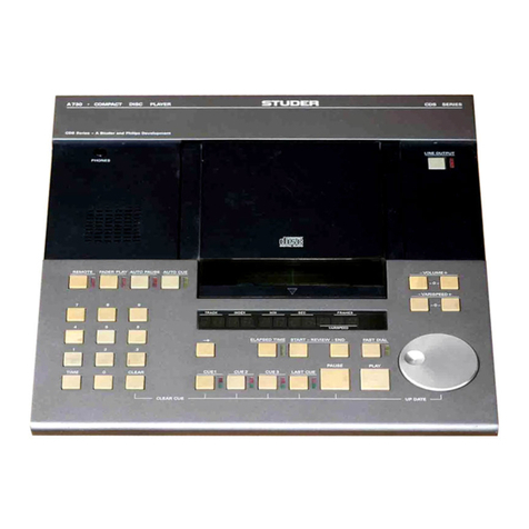
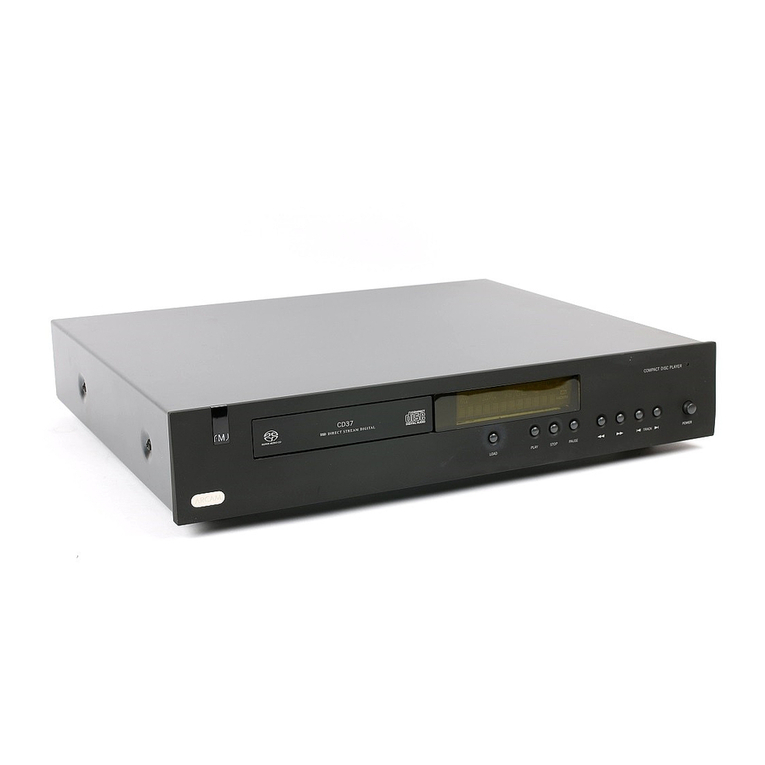
Studer Retrofit Kit MkII User manual

A730 CD Player
16.11.00 BN Upgrade Kit 1.630.027.81 Page 1 of 7
Neues Laufwerk für A730 Umbaukit MkII 1.630.027.81
Grund: Das Laufwerk CDM-4 Die-Cast (1.630.010.08/69, im folgenden Text „LW“ genannt) ist nicht mehr erhältlich;
deshalb wurde ein Umbaukit MkII entwickelt (CD Drive CDM-4/19). Der Umbau ist in dieser Anleitung Schritt
für Schritt beschrieben.
Der Umbaukit MkII 1.630.027.00 enthält folgendes Material:
CD-Laufwerk 1.630.114.00 Montageblech 1.630.110.34
Div. Litzen mit Steckern 1.630.114.93 2 Kabelbinder 35.03.0109
3 Schrauben M3×8 21.53.0355 2 Distanzröhrchen 3,25 mm 1.010.161.27
2 Schrauben M3×10 21.53.0356 1 Senkschraube M3 21.99.0121
Driver Brush Motor Platine 1.630.075.00 4 Distanzröhrchen 2 mm 23.01.2032
Widerstand 22 kΩ57.11.3223 Widerstand 10 kΩ57.11.3103
Widerstand 130 kΩ57.11.3134 Widerstand 56 kΩ57.11.3563
Kondensator 100 nF 59.03.2104 Kondensator 330 nF 59.06.0334
Selbstklebe-Etikette „1.630.072.00“ 1.630.072.10 Selbstklebe-Etikette „1.630.070.20“ 1.630.070.10
Schaumstoff-Klebeband, doppelseitig 65.99.0180 Lötöse 29.26.1002
Der Umbau darf nur von fachkundigem Personal durchgeführt werden. Bitte beachten Sie die Vorschriften für
die Handhabung elektrostatisch empfindlicher Bauteile („ESE“) im Abschnitt „Sicherheit und erste Hilfe“ in der
Service-Anleitung. Verwenden Sie zum Löten unbedingt geeignetes Werkzeug!
Hardware- und Software-Versionen
Für einen erfolgreichen Umbau wird im A730 folgende Hard- und Software vorausgesetzt:
Servo Board: 1.630.051.85/86 Main Board: 1.630.052.22/23/24
Servo Software .23 (IC33): 1.630.066.23/49/90 Control Software .23 (IC3): 1.630.065.23/08/92
Für Servo Board 1.630.051.84 und tiefer muss zusätzlich der Service Kit 1.630.060.00 eingebaut werden
(Servo Board 1.630.051.86 ist Teil dieses Kits). Tragen die oben aufgeführte Baugruppen tieferen Indices
(fettgedruckt), muss der CD-Spieler erst auf aktuellen Stand gebracht werden.
Falls auf dem Main Board gelbe Wire Wrap-Drähte gelötet sind, hat dieses Board den korrekten Index, damit
die Änderung im Abschnitt „Modifikation Main Board“ durchgeführt werden kann. Ist dies nicht der Fall, muss
das „Hardw. Mod. Kit A730“ 20.010.730.03 anstelle des Service Kits 1.630.060.00 für die Modifikation benutzt
werden. Servo Board 1.630.051.86 ist in diesem Kit ebenfalls enthalten.
Vorbereitung und Modifikation
•Trennen Sie das Gerät vom Netz.
•Öffnen Sie das Gerät durch vorsichtiges Entfernen der Frontabdeckung (Bedienungsteil). Lösen Sie dazu
die sechs Innensechskant-Schrauben. Bewahren Sie diese Schrauben auf. Diese sind von der Unterseite
der Front zugänglich; die ganze Frontplatte mit dem LW kann durch Abdrehen nach links auf eine geeignete
Unterlage gelegt werden. Sie blicken nun auf das Servo Board, das unterhalb des LWs montiert ist.
•Entfernen Sie die beiden Flachbandkabel am Main Board und die schwarze Erdungslitze zum Gehäuse. Le-
gen Sie den Gehäuseboden beiseite. Ziehen Sie alle Stecker mit Litzen vom Servo Board und die beiden
Flexprints zum LW ab. Vorsicht: Die Flexprint-Anschlüsse sind verriegelt.
•Entfernen Sie die beiden Zugfedern zwischen Druckguss-Rahmen und LW und bewahren sie sie auf.
•Entfernen Sie das Servo Board und die zugehörigen Montagebügel vom Chassis. Die vier Sicherungsschei-
ben werden wieder gebraucht. Lösen Sie die Spezial-Schrauben (mit Gummidämpfern) von der Frontplatte.
Nun kann das ganze LW entfernt werden.
•Demontieren Sie den Micro-Schalter vom Montageblech (das kleine Gewindeblech wird wieder gebraucht)
und montieren Sie diesen im gleichen Richtungssinn auf das beigepackte, neue Montageblech
(1.630.110.34). Die genaue Positionierung erfolgt später. Demontieren Sie nun das „alte“ Blech, welches mit
zwei Innensechskant-Schrauben am Druckguss-Rahmen befestigt ist. Das neue Blech mit Schalter kommt
nun auf zwei Distanzröhrchen 3,25 mm (1.010.161.27) zu sitzen. Die Befestigung erfolgt mit zwei Schrauben
M3×10 (21.53.0356) und den aufbewahrten Sicherungsscheiben.
•Justieren des Schalters: Durch leichtes Festdrehen der linken Schraube kann der Schalter um eine Achse
gedreht werden. Justieren Sie den Schalter so, dass der Schaltpunkt kurz vor dem Schliessen oder Öffnen
des CD-Deckels erfolgt, aber die Schaltzunge niemals das Schaltergehäuse berührt. Drehen Sie vorsichtig
beide Schrauben fest.
•Das neue LW hat eine mechanische Transportsicherung. Vor dem Einbau müssen die zwei IS-Schrauben
unter der schwarzen Kunststoff-Abdeckung festgedreht werden (ca. 10 Umdrehungen im Uhrzeigersinn).
•Einbau des neuen LW: Es wird über der Öffnung in der Front positioniert und mit den vier aufbewahrten In-
nensechskant-Schrauben so fixiert, dass der Rahmen noch justiert werden kann.

A730 CD Player
16.11.00 BN Upgrade Kit 1.630.027.81 Page 2 of 7
Bracket on front panel
CD drive
•Montieren Sie die aufbewahrten Zugfedern gemäss Figur (die Löcher
für die Zugfedern werden teilweise vom Rahmen verdeckt).
Position des LW
•Die genaue Position des LWs ist wichtig. Zur Justage muss die Bedienungsfront auf den Gehäuseboden
gelegt werden. Nur so kann das LW richtig positioniert werden. Prüfen Sie mit einer eingelegten CD, ob der
Luftspalt entlang seines gesamten Umfangs gleich breit ist. Ist dies der Fall, drehen Sie die vier Schrauben
fest, welche den Rahmen mit der Front verbinden.
Umbau des Servo Boards
•Entfernen Sie die Isolationsfolie und alle selbstklebenden Schaumstoffrückstände auf der Rückseite des
Boards (1.630.051.85/86). Die Isolationsfolie wird später wieder gebraucht.
•Nehmen Sie auf dem Board 1.630.051.85/86 folgende Änderungen vor: R48 (22 kΩ) ersetzen durch 10 kΩ
(57.11.3103); R16 (270 kΩ) ersetzen durch 130 kΩ(57.11.3134); R17 (51 kΩ) ersetzen durch 22 kΩ
(57.11.3223); C21 (68 pF) ersetzen durch 330 nF (59.06.0334) in Serie mit 56 kΩ(57.11.3563).
•Auslöten: TP17, TP18, TP24, TP28, J1, J3, J7, C66, R73 (Potentiometer) und IC6.
•Der 100 nF-Kondensator (59.03.2104) wird an TP19 (HF-RET) angelötet. Sein zweiter Anschluss wird mit
der Lötöse (29.26.1002) verlötet (siehe Figur 1). TP2 und TP3 müssen vorsichtig um 90°abgebogen werden
(siehe Fig. 1; Empfehlung: Vor dem Biegen auslöten).
•Löten Sie nun die vorgefertigten Litzen (1.630.114.93) gemäss Tabelle in die Lötaugen (vorher waren dort
Stecker J1 und J3 montiert). Befestigen Sie den Steckverbinder mit Schaumstoff-Klebeband auf dem Print
(Fig. 4). Binden Sie den Kabelstrang mit Kabelbindern (35.03.0109) gemäss Fig. 4 und 5. Löten Sie die zwei
verdrillten Litzen (brn, blk) an die entsprechenden Punkte auf dem Print (siehe Tabelle/Fig. 1).
•Anstelle von IC6 löten Sie die kleine Platine „Driver Brush Motor“ (1.630.075.00) ein. Der ZIP-Verbinder für
den Flexprint und die damit verbundenen Leitungen kommen teilweise zwischen dem Driver Brush Motor
PCB und dem Servo Board zu liegen, lassen Sie deshalb genügend Abstand zwischen den beiden Platinen.
Details finden Sie in Fig. 1 und 4.
•Vorsicht: Der Raum zwischen LW und Servo Board ist sehr knapp. Die in Fig. 3 grau markierten Lötan-
schlüsse auf der Lötseite des Boards müssen ganz kurz geschnitten werden.
•Schneiden Sie eine rechteckige Schutzfolie gemäss Fig. 1 aus der aufbewahrten Isolation. Abmessungen:
122 mm x 100 mm. Diese wird mit dem beigepackten Schaumstoff-Klebeband (siehe Bild; in
der Mitte des Prints) an 5 Punkten auf der Lötseite des Boards befestigt. Die Schaumstoffstücke müssen
gemäss Fig. 3 positioniert sein, die Folie muss fest angedrückt werden!
•Bohren Sie 2 Löcher ∅3,2 mm in die Folie, so dass sie mit den Montagelöchern des Boards fluchten.
•Falten Sie das Flachbandkabel gemäss Fig. 1. Überkleben Sie die Etikette „1.630.051.86“ mit der Etikette
„1.630.072.00“, löten Sie die braune (roter Punkt) und schwarze Litze an die entspr. Kontakte des Motors.
•Bauen Sie das Servo Board wieder ein. Verwenden Sie die vier 2 mm-Distanzröhrchen zwischen Montage-
rahmen und Platine. Befestigen Sie das Servo Board mit den drei Schrauben M3×8 (21.53.0355) und, beim
Driver Brush Motor PCB, der Senkschraube M3 (21.99.0121).
•Schliessend Sie den Flexprint am ZIP-Verbinder an. Nach dem Verriegeln (Clip in Richtung der Litzen einra-
sten) muss der Verbinder mit einem Stück des Schaumstoff-Klebebandes auf dem Servo Board befestigt
werden, die Position des Verbinders ist in Fig. 4 ersichtlich. Der Flexprint des LWs und die Litzen zum Motor
müssen nach dem Anschliessen ganz lose liegen und dürfen keinesfalls unter mechanischem Zug stehen!
•Bei Verwendung des Service Kits 1.630.060.00 ändern Sie den Stecker des Lock-Magneten gemäss Fig. 7.
Source Destination
J1, pin no. Signal name Wire color Conn. CDM-4 (ZIF), pin no.
1GNDbrn14
2 D1 red 10
3D2org9
4 D3 yel 11
5D4grn12
6Sblu13
7Gvio8
8FOC-gry1
9FOC+wht2
10 LO blk 6
11 LM red 7
12 LG org 5
J3, pin no. Signal name Wire color
1RAD+brn3
2RAD-red4
TP Signal name Wire color DC-Motor, pin
24 +5V brn red dot
28 VM blk no mark

A730 CD Player
16.11.00 BN Upgrade Kit 1.630.027.81 Page 3 of 7
Bestückungsplan Servo Board
Flachbandkabel und Position der Schutzfolie (Ansicht auf Bestückungsseite)
Figur 1; Servo Board (1.630.051.86 heisst nach dem Umbau 1.630.072.00)
FOCUS
OFFSET
LASER
RAD OFFSET
VERANY
Track 38:
min. dropouts
50 mV ±2 mV
Details see fig. 7
0 V ±5 mV
zum Motor
Schutzfolie (Lötseite)
1.630.072.00
100 mm
122 mm
114 mm
(2 x Ø 3.2 mm)
4 mm
Pin 1

A730 CD Player
16.11.00 BN Upgrade Kit 1.630.027.81 Page 4 of 7
Das fertig geänderte Servo Board mit Driver Brush Motor
Umbau des Steckers zum Verriegelungsmagneten
Fig. 2: Driver Brush Motor
1.630.075.00
Fig. 5: Gesamtansicht des umgebauten Servo Boards Fig. 6: Verlegen der Litzen auf dem Main Board
(keine Kabel im Bereich „Chassis Area“).
Fig. 3: Gekürzte Lötstifte und Drahtenden auf Servo Board;
Schutzfolie mit 2 Löchern, auf Lötseite fixiert mit
5 Stk. doppelseitigem Klebeband
Fig. 4: Anschluss ans LW.
Der Flexprint darf keinen mecha-
nischen Zug aufweisen. Der ZIP-
Stecker liegt unterhalb dem
Driver Brush Motor PCB (mit
Schaumstoff-Klebeband auf dem
Servo Board fixiert).
Fig. 7: Das Servo Board 1.630.051.85/86 besitzt für die Verbindung zum Ver-
riegelungsmagneten neu eine 5-polige Buchse (3-polig bei der früheren Versi-
on 1.630.051.00). Das Steckergehäuse muss gemäss Figur durch das 5-polige
Steckergehäuse ersetzt werden (im Kit 1.630.060.00 enthalten). Nach leichtem
Druck auf die Verriegelungsfahne können die Steckkontakte aus dem 3-poligen
Steckergehäuse gezogen werden. Biegen Sie die Verriegelungsfahnen vor
dem Einsetzen in das neue 5 polige Gehäuse vorsichtig wieder etwas auf. Bild
zeigt die Steckposition. Die glatte Seite des Gehäuses muss beim Einstecken
in J4 des Servo Boards nach oben weisen.
Hinweis: Der 3-polige Stecker kann weiter verwendet werden. Beachten Sie in
diesem Fall die Zuordnung von Litzenfarbe und Anschlussnummer (Pin1: oran-
ge, Pin2: grau).
pin1
org
gry

A730 CD Player
16.11.00 BN Upgrade Kit 1.630.027.81 Page 5 of 7
Modifikation Main Board
Da das neue LW mehr Platz beansprucht, muss auch das Main Board modifiziert werden. Die folgenden
Änderungen verhindern das Berühren der Ringkern-Spule L2. Das Main Board muss dazu ausgebaut werden.
•Löten Sie R39 und DL3 aus. Diese Teile werden nicht mehr gebraucht.
•L2 kommt in eine liegende Position. L2 sollte dazu komplett ausgelötet werden. Ein Anschluss von L2 wird
verlängert (eine Windung vom Kern abwickeln). Die Anschlussdrähte werden so gebogen, dass L2 nun lieg-
end montiert, mit Heiss- oder Silikonkleber auf dem Print fixiert und festgelötet werden kann.
•Das Servo Board wird J3 berühren. J3 muss daher um 180°gedreht werden, der Verpolungsschutz (Draht)
muss von Pin6 (J3) auf Pin 3 (J3) umgesteckt werden. Vorsicht: Vor dem Einlöten von J3 muss ein Rest der
zerschnittenen Isolationsfolie (oder allenfalls ein geeignetes Stück Papier) zur Isolation zwischen J3 und den
Print gelegt werden (Kurzschlussgefahr mit Leiterbahnen)!
•Überkleben Sie die bestehende Etikette „1.630.052.22/23/24“ mit der Etikette „1.630.070.20“.
•Nun wird das Main Board wieder eingebaut und angeschlossen. Vorsicht: Beachten Sie unbedingt, wie die
Litzen mit den Filtern (ggf. in Schrumpfschlauch) zum Line-Verstärker hin verlegt sind (siehe Fig. 6). Sie
dürfen beim Montieren der Front durch diese weder berührt noch gequetscht werden.

A730 CD Player
16.11.00 BN Upgrade Kit 1.630.027.81 Page 6 of 7
Geändertes Schema Servo Board
130
k
22k
330n 56k
+5V
Disc DC-Moto
r
IC6=1.630.075.XX
10k
brown wire
black wire

A730 CD Player
Studer is a registered trade mark of Studer Professional Audio AG, Regensdorf Page 7 of 7
Elektrische Einstellungen des Servo Boards
•Stecken Sie die beiden Flachbandkabel und die Masseverbindung wieder an. Legen Sie die Frontplatte mit
dem neuen LW auf das Gehäuse. Bringen Sie die Frontplatte durch geeignete Stützen in eine erhöhte Lage,
die möglichst parallel zur eingebauten Position sein sollte.
•Voreinstellung: Drehen Sie R23 auf Rechtsanschlag (im Uhrzeigersinn). Der Laserstom ist nun auf Mini-
mum eingestellt. Bringen Sie R33 und R77 in Mittelstellung. Schalten Sie das Gerät ein. Beobachten Sie, ob
sich die Linse beim Verdrehen von R33 auf und ab bewegt. Wenn ja, bringen Sie R33 wieder in Mittelstel-
lung zurück. Andernfalls überprüfen Sie die Verdrahtung des neuen Kabelbundes mit dem Servo Board.
Prüfen Sie, ob der Flexprintanschluss bündig im ZIF-Stecker am Kabel sitzt.
•Disc Motor Gain: Der Verstärkungsfaktor für den Disc-Motor ist nun fix und braucht nicht mehr eingestellt zu
werden.
•Laserstrom: Legen Sie die Test-CD „Philips SBC444“ ein (Bestell-Nr. siehe Tabelle unten). Schliessen Sie
den Deckel. Betätigen Sie die PLAY-Taste wiederholt und verstellen Sie R23 im Gegenuhrzeigersinn, bis Sie
zwischen TP2 und TP3 eine Spannung von 50 ±2 mV messen. Wenn das Inhaltsverzeichnis der CD („TOC“)
einwandfrei gelesen wird, erscheinen in der Anzeige zwei Balken.
•Focus Offset: Stellen Sie während dem Abspielen der CD zwischen TP7 und TP25 mit R33 eine Spannung
von 0 ±5 mV ein. Hinweis: Die Dicke der eingelegten Disk (nominale Dicke: 1,23 mm) hat einen entschei-
denden Einfluss auf die Einstellung des Focus Offset. Die Test-CD „Philips SBC444“ entspricht dieser Spe-
zifikation.
•Radial Offset: Legen Sie die Test-CD „Vérany Digital Test #2” ein (Bestell-Nr. siehe Tabelle unten). Justie-
ren Sie bei Track 38 mit R77 den abgespielten Sinus-Ton so, dass keine oder nur minimale Aussetzer zu
hören sind.
Behelfsmässige Variante: Stehen weder Vérany- noch Philips-Test CDs zur Verfü-
gung, stellen Sie R77 wie nebenstehend abgebildet ein.
•Der Umbau ist nun abgeschlossen, Sie können das Gerät definitiv schliessen.
Transportsicherung
Das neue LW hat eine mechanische Transportsicherung. Zwei IS-
Schrauben 2,5 mm sichern das LW. Vor einem Transport müssen
diese beiden Schrauben im Gegenuhrzeigersinn (ca. 10 Umdre-
hungen nach links) gedreht werden. Das LW wird dabei in einer
definierten Position festgehalten.
Vor der Inbetriebnahme müssen diese Schrauben wieder festge-
dreht werden (ca. 10 Umdrehungen im Uhrzeigersinn).
Test-CDs
Typ Studer-Bestell-Nr.
Philips SBC444 und SBC444 A 10.241.026.01
Vérany Digital Test #1 und #2 10.693.001.00
Prepared and edited by: Copyright by Studer Professional Audio AG
Studer Professional Audio AG Printed in Switzerland
Technical Documentation
Althardstrasse 30
CH-8105 Regensdorf – Switzerland Subject to change
unlock
lock unlocklock
Laser
pickup

A730 CD Player
16.11.00 BN Upgrade Kit 1.630.027.81 Page 1 of 7
New CD Drive for A730 Retrofit Kit MkII 1.630.027.81
Reason: The CD drive CDM-4 Die-Cast (1.630.010.08/69) is no more available. Therefore, the Retrofit Kit MkII (with
CD drive CDM-4/19) has been developed. The following text contains step-by-step upgrade instructions.
Contents of Retrofit Kit MkII 1.630.027.00
CD drive 1.630.114.00 Mounting bracket 1.630.110.34
Div. wires w. connectors 1.630.114.93 2 Wire straps 35.03.0109
3 Screws M3×8 21.53.0355 2 Spacer bushes 3.25 mm 1.010.161.27
2 Screws M3×10 21.53.0356 1 Countersunk screw M3 21.99.0121
Driver Brush Motor PCB 1.630.075.00 4 Spacer bushes 2 mm 1.010.098.27
Resistor 22 kΩ57.11.3223 Resistor 10 kΩ57.11.3103
Resistor 130 kΩ57.11.3134 Resistor 56 kΩ57.11.3563
Capacitor 100 nF 59.03.2104 Capacitor 330 nF 59.06.0334
Label “1.630.072.00” 1.630.072.10 Label “1.630.070.20” 1.630.070.10
Auto-adhesive foam tape 65.99.0180 Solder lug 29.26.1002
The upgrade may be performed by trained personnel only. Please consider the prescriptions for handling of
electrostatically sensitive components (“ESE”) in the “Safety” section at the beginning of the service manual.
Take care to use only appropriate tools for unsoldering and soldering!
Hardware and Software Versions
The following hardware and software modification indices are prerequisites for successful modification:
Servo Board: 1.630.051.85/86 Main Board: 1.630.052.22/23/24
Servo Software .23 (IC33): 1.630.066.23/49/90 Control Software .23 (IC3): 1.630.065.23/08/92
For Servo Boards 1.630.051.84 and lower, the Service Kit 1.630.060.00 must be installed in addition (Servo
Board 1.630.051.86 is part of this Service Kit). If the abovementioned assemblies have lower modification in-
dices (the part of the order no. printed in bold characters), the A730 CD Player must be updated before.
If yellow wrap wires are installed on the Main Board, then the Board has the correct modification status for a
successful upgrade according to the “Main Board Modification” paragraph. Should this not be the case,
please use the “Hardw. Mod. Kit A730” 20.010.730.03 for the modification instead of the Service Kit
1.630.060.00. The Servo Board 1.630.051.86 is contained in this kit, too.
Preparation, Modification
•Unplug the unit from the mains.
•Open the unit by carefully removing the front (operating) panel by means of unscrewing the six Allen screws
accessible from the bottom side. The complete front panel with the drive can then be flipped-over to the left
and placed onto your workbench next to the bottom part of the CD player. Now you see the Servo Board in-
stalled at the rear of the CD drive.
•Unplug the two flat ribbon cables from the Main Board and the black ground wire to the housing. Put the
bottom part of the CD player aside. Unplug all connectors and flex PCBs (after having opened the locks on
the flex PCB connectors) from the Servo Board.
•Remove both tension springs between the die-cast frame and the CD drive. Put them aside for later use.
•Remove the Servo Board and its mounting brackets from the chassis. Put the four lock washers aside for
later use. Unscrew the special screws with rubber dampers from the front panel. Now the complete CD drive
can be removed.
•Remove the microswitch from its mounting bracket (take care not to lose the small threaded part) and rein-
stall the microswitch in the same direction to the new mounting bracket (1.630.110.34) contained in the kit.
Exact positioning of the microswitch will be performed later. Now remove the “old” mounting bracket which is
fixed to the die-cast frame with two Allen screws. The new mounting bracket with the switch installed must be
fixed to the die-cast frame using the two 3.25 mm spacers between the bracket and the frame. Use two
screws M3×10 (21.53.0356) and the lock washers put aside before.
•Microswitch adjustment: Slightly tighten the left screw in such a way that the switch can still be rotated
around this pivot. Adjust the switch so that the switching point is just before closing or opening the hinged
CD cover; the switching lever must never touch the switch body. When finished, carefully tighten both
screws.
•The new CD drive has a mechanical transport lock. Before installing it, the two Allen screws (key no. 2.5) ac-
cessible through holes in the black plastic cover must be tightened (approx. 10 turns clockwise). Having
done this, the drive is ready for installation.
•Installation of the new CD drive: The new drive is placed over the front panel opening and loosely fixed with
the four Allen screws put aside before, so that the drive frame still can be shifted.

A730 CD Player
16.11.00 BN Upgrade Kit 1.630.027.81 Page 2 of 7
Bracket on front panel
CD drive
•Fit the two tension springs put aside before according to the figure;
the spring mounting holes are partially covered by the CD drive
frame.
Position of the CD drive
•The exact position of the CD drive is important. For adjustment, the front panel must be placed to the bottom
of the player. Check with an inserted CD if the air gap is of equal width around the circumference of the disk.
If so, tighten the four screws linking the CD drive frame with the front panel.
Servo Board Modification
•Remove the insulating sheet and all remainders of the adhesive foam tape from the solder side of the board
(1.630.051.85/86). Put the insulating sheet aside for later use.
•Perform the following modifications on the Board (1.630.051.85/86): R48 (22 kΩ), replace by 10 kΩ
(57.11.3103); R16 (270 kΩ), replace by 130 kΩ(57.11.3134); R17 (51 kΩ), replace by 22 kΩ(57.11.3223);
C21 (68 pF) , replace by 330 nF (59.06.0334) in series with 56 kΩ(57.11.3563).
•Remove the following parts: TP17, TP18, TP24, TP28, J1, J3, J7, C66, R73 (trimmer pot), and IC6.
•The 100 nF capacitor (59.03.2104) is connected to TP19 (HF-RET); its second terminal is soldered to the
solder lug (29.26.1002), refer to fig. 1. Test points TP2 and TP3 must be bent by 90°, refer to fig.1; we ur-
gently recommend to unsolder them before bending.
•Solder the pre-fabricated wires (1.630. 114.93) to the corresponding solder pads according to the table be-
low and to fig. 1 (at the former positions of connectors J1 and J3). Tie the cables with the wire straps
(35.03.0109) according to fig. 4 and 5. Solder the two twisted wires (brn, blk) to the corresponding pads on
the PCB (refer to the table below and to fig. 1).
•Solder the small Driver Brush Motor PCB (1.630.075.00) at the location of IC6. The ZIP connector for the flex
PCB and its wires will be located between the Driver Brush Motor PCB and the Servo Board, therefore
please leave sufficient space between the two PCBs. For details please refer to fig. 1 and 4.
•Caution: The clearance between the CD drive and the Servo Board is extremely narrow; therefore the com-
ponent leads on the solder side marked grey in fig. 3 must be cut very short.
•Cut a rectangular insulating sheet (dimensions: 122 x 100 mm) out of the insulating sheet put aside before;
refer to fig. 1. Fix this insulating sheet as shown in fig. 3 to the solder side of the Servo Board, using five
pieces of the double-sided adhesive foam tape contained in the kit. The foam tape has to be positioned ac-
cording to fig. 1 and 3; press the insulating sheet firmly to the foam tape.
•Drill two holes ∅3.2 mm into the insulating sheet such that they match the two mounting holes of the PCB.
•Fold the flat ribbon cable as shown in fig. 1. Stick the label “1.630.072.00” over the label “1.630.051.86” and
solder the two twisted wires to the motor’s soldering tags (brn wire to red dot).
•Reinstall the Servo Board, using the four 2 mm spacers (1.010.165.27) between mounting frame and Servo
Board. Fix the Servo Board with the three M3×8 screws (21.53.0355), and the countersunk screw M3
(21.99.0121) next to the Driver Brush Motor PCB.
•Connect the Flex PCB to the ZIP connector. After having locked the connector (shift the locking clip towards
the wire end of the connector), it must be fixed to the Servo Board using a piece of double-sided adhesive
foam tape. Position the connector exactly as indicated in fig. 4 – the flex PCB of the CD drive as well as the
two wires to the motor must be free in all directions – it must by no means be under tensile stress.
•If using the additional Service Kit 1.630.060.00, replace the 3-pin housing of the lock solenoid connector
(plugged to socket J4) by the 5-pin housing contained in the kit, refer to fig. 7.
Source Destination
J1, pin no. Signal name Wire color Conn. CDM-4 (ZIF), pin no.
1GNDbrn14
2 D1 red 10
3D2org9
4 D3 yel 11
5D4grn12
6Sblu13
7Gvio8
8FOC-gry1
9FOC+wht2
10 LO blk 6
11 LM red 7
12 LG org 5
J3, pin no. Signal name Wire color
1RAD+brn3
2RAD-red4
TP Signal name Wire color DC-Motor, pin
24 +5V brn red dot
28 VM blk no mark

A730 CD Player
16.11.00 BN Upgrade Kit 1.630.027.81 Page 3 of 7
Servo Board, Component Placement
Flat Ribbon Cable and Insulating Sheet Position (Component Side View)
Fig. 1: Servo Board (assy. no. changed from 1.630.051.86 to 1.630.072.00 after modification)
FOCUS
OFFSET
LASER
RAD OFFSET
VERANY
Track 38:
min. dropouts
50 mV ±2 mV
Details see fig. 7
0 V ±5 mV
To motor
Insulating sheet
(on solder side)
1.630.072.00
100 mm
122 mm
114 mm
(2 x Ø 3.2 mm)
4 mm
Pin 1

A730 CD Player
16.11.00 BN Upgrade Kit 1.630.027.81 Page 4 of 7
Modified Servo Board, Driver Brush Motor
Lock solenoid connector
Fig. 2: Driver Brush Motor
1.630.075.00
Fig. 4: Connection to CD drive.
The flex PCB must by no means
be under tensile stress. The ZIP
connector is located below the
Driver Brush Motor PCB and is
fixed to the Servo Board with auto-
adhesive foam tape.
Fig. 5: View of the modified Servo Board Fig. 6: Wire placement on Main Board
(no wires in “Chassis Area”!).
Fig. 3: Cut pin and wire ends on Servo Board;
Insulating sheet w. 2 holes, fixed on solder side
with 5 pcs. of self-adhesive foam tape
Fig. 7:
On the Servo Board 1.630.051.85/86 a 5-pin connector is used for the connec-
tion to the lock solenoid (the former version 1.630.051.00 had a 3-pin connector).
Remove the two pin contacts from the former connector housing by carefully
pressing down the detent spring with a pointed tool while pulling.
Slightly bend the detent springs of the pin contacts up again and insert them into
the 5-pin connector housing (contained in the kit 1.630.060.00).
The flat part of the connector housing must face upwards when plugging it into J4
on the Servo Board.
Note: Of course, the 3-pin connector can be used as well, provided the wire co-
lour/pin assignment is correct.
Pin1
org
gry

A730 CD Player
16.11.00 BN Upgrade Kit 1.630.027.81 Page 5 of 7
Main Board Modification
Due to the larger size of the new CD drive, the Main Board must be modified as well. The following changes
avoid the toroidal inductor L2 from being touched. For this purpose, the Main Board must be removed.
•Unsolder R39 and DL3; these components are used no more.
•L2 has to be installed in a horizontal position. For this behalf, it should be unsoldered. One of its leads must
be extended by unwinding one turn. Bend the leads in such a way that L2 can be mounted horizontally; fix it
to the PCB with hot-melt or silicone adhesive and solder its leads to the corresponding pads.
•The Servo Board will be touching J3. Therefore J3 must be rotated by 180°. Unsolder J3, move the key wire
from pin6 to pin3. Caution: Before inserting and soldering J3 in its new position, put an appropriate cutting
of the insulating sheet (or possibly a piece of solid paper) between J3 and the PCB, as an insulation against
the PCB tracks.
•Replace the label “1.630.052.22/23/24” by the label “ 1.630.070.20”.
•Reinstall and connect the Main Board. Caution: Take care to the placement of the wires with the filters (pos-
sibly in shrinking tube) relative to the Line Amplifier (refer to fig. 6). When installing the front panel, these fil-
ters must neither be touched nor pinched.

A730 CD Player
16.11.00 BN Upgrade Kit 1.630.027.81 Page 6 of 7
Modified Servo Board Diagram
130
k
22k
330n 56k
+5V
Disc DC-Motor
IC6=1.630.075.XX
10k
brown wire
black wire

A730 CD Player
Studer is a registered trade mark of Studer Professional Audio AG, Regensdorf Page 7 of 7
Electrical Adjustments
•Plug the two flat cables and the ground lead to their corresponding connectors. Place the front panel with the
new CD drive above the unit’s bottom, using appropriate supports so that the front panel is parallel to its in-
stalled position.
•Preadjustment: Turn R23 to its clockwise stop. Laser current is set now to its minimum setting. Turn R33
and R77 to their center positions. Switch the unit on. Verify if the pickup lens moves up and down when ad-
justing R33. If so, set R33 back to its center position. If not, check the wiring of the new cables to the Servo
Board, and also check if the flex PCB is completely plugged into the ZIF connector.
•Disc Motor Gain: This setting is fixed now, no adjustment required.
•Laser Current: Insert a the “Philips SBC444” test CD (order no. see table below). Close the hinged cover.
Press PLAY repeatedly and adjust R23 counterclockwise until a voltage of 50 ±2 mV can be measured be-
tween TP2 and TP3. If the CD’s table of contents (“TOC”) can be read, two bars appear in the display.
•Focus Offset: While the CD is playing, adjust the voltage between TP7 and TP25 to 0 ±5 mV with R33. Tip:
The thickness of the inserted disc has a crucial influence on the focus offset adjustment and refers to a
nominal disc thickness of 1.23 mm. The Philips SBC444 test disc fulfills this specification.
•Radial Offset: Insert the “Vérany Digital Test #2” test CD (order no. see table below). Play track 38 and ad-
just with R77 the reproduced sine-wave to minimum dropouts.
Workaround: If neither the Vérany nor the Philips test CDs are available, set R77 to a
position corresponding to “01:30” on a clock dial (no matter whether AM or PM), as
shown at the right.
•The upgrade is terminated now, the CD player can be reassembled.
Transport Lock
The new CD drive has a mechanical transport lock. Before trans-
porting the unit, two Allen screws (key no. 2.5) must be released
(approx. 10 turns counterclockwise). If so, the drive is fixed in a de-
fined position.
These screws must be tightened (approx. 10 turns clockwise) be-
fore the unit is put into operation again.
Test CDs
Type Studer order no.
Philips SBC444 and SBC444 A 10.241.026.01
Vérany Digital Test #1 and #2 10.693.001.00
Prepared and edited by: Copyright by Studer Professional Audio AG
Studer Professional Audio AG Printed in Switzerland
Technical Documentation Order no. 10.27.4166 (Ed. 1100)
Althardstrasse 30
CH-8105 Regensdorf – Switzerland Subject to change
unlock
lock unlocklock
Laser
pickup
This manual suits for next models
1
Table of contents
Languages:
Other Studer CD Player manuals
