Studer OnAir 2500 User manual

OnAir 2500 Digital Mixing Console
Quick Reference Guide 1
Document generated: 09.09.14
ONAIR 2500 QUICK REFERENCE
OnAir 2500 Quick Reference ..................................................................................................................................................... 3
1 What You See Is What You Got.................................................................................................................................. 4
2 Safety Information ...................................................................................................................................................... 4
3 First Aid ...................................................................................................................................................................... 4
4 Earthing....................................................................................................................................................................... 5
5 Dimensions ................................................................................................................................................................. 5
6 Setup of the Fixed-frame Version ............................................................................................................................... 7
7 Setup of the Modulo Version .................................................................................................................................... 10
8 Power-up................................................................................................................................................................... 12
9 The Fader Strip ......................................................................................................................................................... 12
10 Connector Pin Assignments...................................................................................................................................... 13
11 Optional External Units ............................................................................................................................................ 14

OnAir 2500 Digital Mixing Console
2 Quick Reference Guide Document generated: 09.09.14
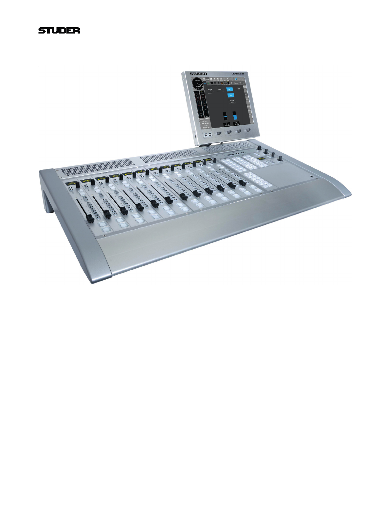
OnAir 2500 Digital Mixing Console
Quick Reference Guide 3
Document generated: 09.09.14
ONAIR 2500 QUICK REFERENCE
Main Features • All-in-oneconsoledesign–no additionalcorerequiredforoperation;
an optional, external D21m I/O frame for additional I/O can be connected
via MADI
• Also available as OnAir 2500 Modulo, with rackmountable DSP mainframe
and furniture-recessable fader modules
• 12,18or24faderlayoutwith100mmmanualfaders(motorfadersoptional)
• Touch-sensitive 12”colorTFTscreen,fourrotaryencodersfor parameter
adjustment. Ergonomic, easy-to-learn Touch’n’Action user interface
• OrganicLED(OLED)displaysinfaderstripsandcentralmoduleforclearest
indication
• Redlightsforon-airandopenmicindicationinmainandsecondarystudio.
• AudioI/Oinestablishedsignalformats(analogmic/lineinputs,lineI/O,AES/
EBUI/O,MADI,ADAT,IEEE-1394Firewire,Livewire,etc..)
• Everychannelinputwithfour-bandparametricEQandfulldynamics(com-
pressor,limiter,noisegate,expander,de-esser)
• Onestereoprogrambus,onestereorecordbus,twostereoAUXbusesand
eightstereoMix-Minus(N–1/N–X)buses
• VoiceMix,StuderAuto-Mixalgorithm(optional)
• Configurablekeyfunctionsincasecustomizationisneeded
• EasynetworkingandintegrationthankstoI/OsharingandCMS(StuderCall
ManagementSystem)support
• CompleteintegrationwithRadioAutomationSystems;Monitoraprotocolvia
serial interface or tunnelled via TCP/IP
• ConfigurableroutercontrolviaProBel1
OnAir 2500 Digital Mixing Console
4 Quick Reference Guide Document generated: 09.09.14
1 What You See Is What You Got
• OnAir2500digitalmixingconsole
• Mainscreenwithstandandfourmountingscrews(M4×10)
• MainscablewithIECconnectorandthreemainsplugs(forG/F,UK,US)
• Toolset(consistingofAllenscrewdrivers2/2.5/3mm,USBstick,237-pin
Sub-DplugsforGPIOsockets,5faderknobs,1rotaryknob,6keycaps)
• Thisquickreferenceinstructionleaflet
• Talkbackmodule(optional;includingoneADATandoneCat5cable)
• Redundantpowersupplyunit(PSU)(optional;includingmainscablewith
IECconnectorandDCsupplycable5m)
It is a good idea to keep the original packing materials in case that your unit
needs to be transported.
2 Safety Information
CAUTION
RISK OF ELECTRIC SHOCK
DO NOT OPEN
ACHTUNG
GEFAHR: ELEKTRISCHER SCHLAG
NICHT ÖFFNEN
ATTENTION
RISQUE DE CHOC ELECTRIQUE
NE PAS OUVRIR
Toreducetheriskofelectricshock,donotremovecovers.Nouser-serviceable
partsinside.Refer servicingtoqualifiedservicepersonnel (i.e.,persons
having appropriate technical training and experience necessary to be aware
ofhazardstowhichtheyareexposedinperformingarepairaction,andof
measurestominimizethedangerofthemselves).
This symbol alerts the user to the presence of un-insulated dangerous voltage
withintheequipmentthatmaybeofsufficientmagnitudetoconstitutearisk
of electric shock to a person.
CLASS 1
LASER PRODUCT
CLASS 1
LED PRODUCT
Assemblies or sub-assemblies of this product can contain opto-electronic
devices.AslongasthesedevicescomplywithClassIoflaserorLEDprod-
uctsaccordingtoEN60825-1:1994,theywillnotbeexpresslymarkedon
the product. If a special design should be covered by a higher class of this
standard, the device concerned will be marked directly on the assembly or
sub-assembly in accordance with the above standard.
3 First Aid
In Case of Electric Shock Separatethepersonasquicklyaspossiblefromtheelectricpowersourceby
switchingtheequipmentoff,byunpluggingordisconnectingthemainscable,
or by pushing the person away from the power source, using dry insulating
material(suchaswoodorplastic).
ALWAYS CONSULT A DOCTOR AFTER HAVING SUFFERED AN
ELECTRIC SHOCK.
Warning! Do not touch the person or his clothing before the power is turned off,
OTHERWISE YOU STAND THE RISK OF SUFFERING AN ELEC-
TRIC SHOCK AS WELL!
If the Person is Unconscious Laythepersondown,turnhimtooneside,checkthepulse.Reanimatethe
person if respiration is poor, AND CALL FOR A DOCTOR IMMED-
IATELY.
For additional information on safety, earthing, EMC, conformity declarations
and related subjects, please refer to the Operating Instructions file on this
same CD.
OnAir 2500 Digital Mixing Console
Quick Reference Guide 5
Document generated: 09.09.14
4 Earthing
Earthingofunitswith mains supply(classIequipment)isperformedvia
theprotectiveearth(PE)conductorintegratedinthemainscable.Unitswith
batteryoperation(<60V,classIIIequipment)mustbeearthedseparately.
Earthing the unit is one of the measures for protection against electrical shock
hazard(dangerousbodycurrents).Hazardousvoltagemaynotonlybecaused
by a defective power supply insulation, but may also be introduced by the
connected audio or control cables.
If the unit is installed with one or several external connections, its earthing
must be provided during operation as well as while the unit is not operated.
If the earthing connection can be interrupted, e.g. by unplugging the mains
plug of an external power supply unit, an additional, permanent earthing con-
nection must be installed using the provided earth terminal.
For additional information on earthing, please refer to the Operating Instruc-
tions file on this same CD.
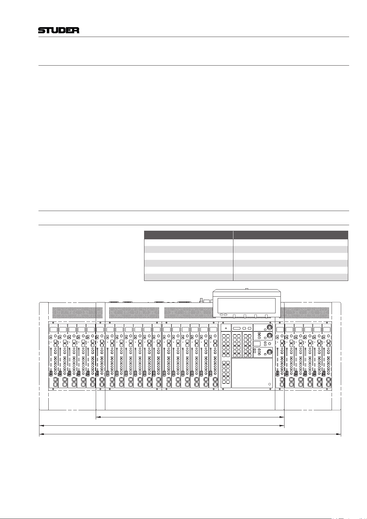
5 Dimensions
Fixed-frame Versions
OnAir 2500 Versions Order no.
12 faders 1.943.600.00
12 motor faders 1.943.605.00
18 faders 1.943.601.00
18 motor faders 1.943.606.00
24 faders 1.943.602.00
24 motor faders 1.943.607.00
524 mm / 20.7”
130 mm / 5.1”
392 mm / 15.5”
1300 mm / 51.2” (24 Fader)
1056 mm / 41.6” (18 Fader)
122 mm / 4.8”
8 mm / 0.3”
40 mm / 1.6” 732 mm / 28.8” (12 Fader)
812 mm / 32” (12 Fader)
465 mm / 18.3”

OnAir 2500 Digital Mixing Console
6 Quick Reference Guide Document generated: 09.09.14
524 mm / 20.7”
130 mm / 5.1”
392 mm / 15.5”
1300 mm / 51.2” (24 Fader)
1056 mm / 41.6” (18 Fader)
122 mm / 4.8”
8 mm / 0.3”
40 mm / 1.6” 732 mm / 28.8” (12 Fader)
812 mm / 32” (12 Fader)
465 mm / 18.3”
Modulo Version
cut-out 301 mm / 11.85”
244 mm / 9.6”
Fader ModuleCentral Module
Core Frame
Front View
Rear View
cut-out 245 mm / 9.65”
300 mm / 11.8”
cut-out 301 mm / 11.85”
244 mm / 9.6”
300 mm / 11.8”
60 mm
2.4”
cut-out 245 mm / 9.65”
64 mm
2.6”
260 mm / 10.2”
269 mm / 10.6” 207 mm / 8.2”
39 mm / 1.6”
275 mm / 10.8”
284 mm / 11.2”
292 mm / 11.5”
Screen Module
483 mm / 19”
380 mm / 15”
222 mm / 8.8” (5U)

OnAir 2500 Digital Mixing Console
Quick Reference Guide 7
Document generated: 09.09.14
cut-out 301 mm / 11.85”
244 mm / 9.6”
Fader ModuleCentral Module
Core Frame
Front View
Rear View
cut-out 245 mm / 9.65”
300 mm / 11.8”
cut-out 301 mm / 11.85”
244 mm / 9.6”
300 mm / 11.8”
60 mm
2.4”
cut-out 245 mm / 9.65”
64 mm
2.6”
260 mm / 10.2”
269 mm / 10.6” 207 mm / 8.2”
39 mm / 1.6”
275 mm / 10.8”
284 mm / 11.2”
292 mm / 11.5”
Screen Module
483 mm / 19”
380 mm / 15”
222 mm / 8.8” (5U)
6 Setup of the Fixed-frame Version
Location The console must be set up on a flat surface. In any case, free air circulation
must be guaranteed through all the air vents on the console’s bottom, side,
rear and top. The air vents must never be covered with e.g. a notepad or a
manual. The console must never be placed on a soft surface, and the rubber
feet at its bottom must not be removed.
Temperature Regulations The unit must not be used in conditions of excessive heat or cold, near any
source of moisture, in excessively humid environments, or in positions where
it is likely to be subjected to vibration or dust. The ambient temperature range
for normal operation of the unit is +5...+35° C.
Assembly Fix the main screen with the four supplied screws to the mounting holes [1]
attheconsole’srear;amatchingAllenkeyissupplied.Connectthescreen’s
cable to the rear-panel SCREEN [2] socket.

OnAir 2500 Digital Mixing Console
8 Quick Reference Guide Document generated: 09.09.14
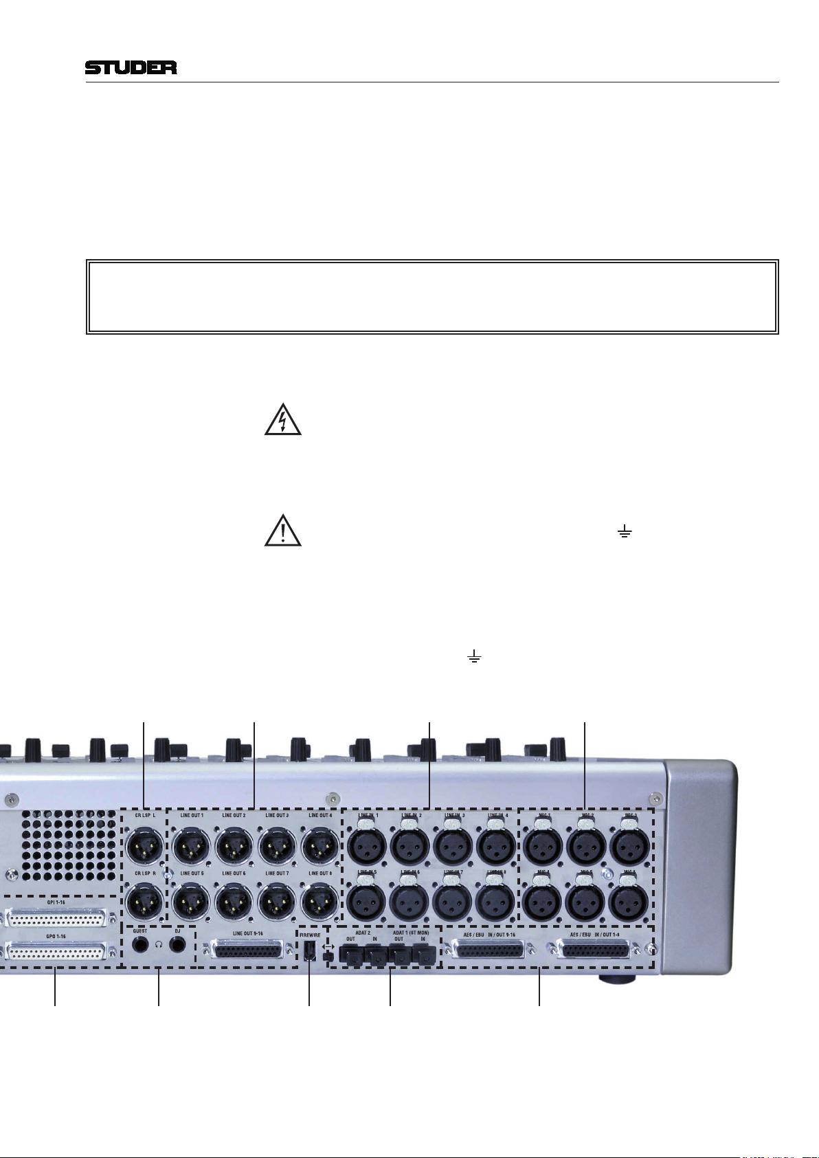
Analog
Line In
Screen Mount Screen Studio
Mon/TB
Box
Earth
Term-
inal
24 VDC
Inlet
Mains
Inlet/
Switch
AES/EBU I/O
CR Monitor
Speakers Out
USB Socket
Analog
Line Out
Microphone
In
LAN RS422
RS232
MADI
Main
DC
Out
MADI
Aux
WCLK
In
AES/EBU
Sync In
GP In
GP Out
Phones Firewire Optical
ADAT I/O
OnAir 2500 Digital Mixing Console
Quick Reference Guide 9
Document generated: 09.09.14
Analog
Line In
Screen Mount Screen Studio
Mon/TB
Box
Earth
Term-
inal
24 VDC
Inlet
Mains
Inlet/
Switch
AES/EBU I/O
CR Monitor
Speakers Out
USB Socket
Analog
Line Out
Microphone
In
LAN RS422
RS232
MADI
Main
DC
Out
MADI
Aux
WCLK
In
AES/EBU
Sync In
GP In
GP Out
Phones Firewire Optical
ADAT I/O
Signal Connection Connect your inputs and output signals. For a basic test hookup a digital signal
(AES / EBU IN / OUT [3])orananaloglinesource(LINEIN [4])andapairof
activemonitorloudspeakers(CR LSP [5])orheadphones(DJ [6])willdo.
An optional talkback module can be connected to the optical ADAT 1 (ST MON)
[7] input/output and to the ST MON [8] socket.
Anoptionalexternal/redundantpowersupplyunit(PSU)isconnectedtothe
24V DC IN [9] socket.
*Caution Connectors are identical on ST MON MODULE and LAN cables.
Make sure not to mix them up since the ST MON MODULE
socket carries DC supply voltage!
Mains Voltage Thepowersupplyunitisauto-ranging;itcanbeusedformainsvoltagesin
a range of 100 to 240 V
AC,50to60Hz.
Power Connection Connect your signal input and output cables before connecting the console
to the mains outlet. Thesuppliedmainscable(withfemaleIEC320/C13
socket)mustbeconnected to amainsplugmatchingyour local standard
(German/French,UKand USversionssupplied)by atrainedtechnician,
respecting your local regulations. Plug the mains cable to the 100-240V~ [10]
mains inlet.
Earthing Some consideration must be given to the earthing arrangement of the system,
at the center of which is the console frame. The frame is earthed to the mains
earth via the power supply or the earth terminal [11]. Ground loops may
occurwheresignalprocessingequipment,patchedtotheframe,hasitssignal
earth commoned to the console chassis.
The console must be earthed, due to the mains input filter network being
connected to the mains earth. If the earthing connection can be interrupted,
for example, by unplugging the mains plug of an external power supply unit,
an additional, permanent earthing connection must be installed using the
provided earth terminal [11].

OnAir 2500 Digital Mixing Console
10 Quick Reference Guide Document generated: 09.09.14
For additional information on ambient temperature, mains connection and
earthing please refer to the Operating Instructions file on this same CD.
7 Setup of the Modulo Version
Mounting Thefadermodulesaswellasthecentralmodulecanbeush-mountedinto
atableorfurniture.Thecoreframecanberackmountedina19”rack.Free
air circulation must be guaranteed through all the air vents of the core frame
Wiring Fader- / TB modules Please note that the maximum distance between the core frame and the moni-
toring/TB module is 60m.
Please note that the maximum distance between the core frame and the fader
modules is 18m.
Cable Type Cat 5e, with shielded connectors on both ends
*Caution Connectors are identical on ST MON, FADER MODULE and LAN
cables. Make sure not to mix them up since the ST MON and
FADER MODULE sockets carry DC supply voltage!
Wiring Central module / Screen Please note that the maximum distance between the core frame and main
screen and central module is 2m !
Temperature Regulations The units must not be used in conditions of excessive heat or cold, near any
source of moisture, in excessively humid environments, or in positions where
it is likely to be subjected to vibration or dust. The ambient temperature range
for normal operation of the unit is +5...+35° C.
Signal Connection Connect your inputs and output signals. For a basic test hookup a digital signal
(AES / EBU IN / OUT)orananaloglinesource(LINE IN)andapairofactive
monitorloudspeakers(CR LSP)orheadphones(DJ)willdo.
An optional talkback module can be connected to the optical ADAT 1 (ST MON)
input/output and to the ST MON socket.
Mains Voltage Thepowersupplyunitisauto-ranging;itcanbeusedformainsvoltagesin
arangeof100to240VAC,50to60Hz.
Power Connection Connect your signal input and output cables before connecting the console to
the mains outlet. Thesuppliedmainscable(withfemaleIEC320/C13socket)
mustbeconnectedtoamainsplugmatchingyourlocalstandard(German/
French,UKandUSversionssupplied)byatrainedtechnician,respecting
your local regulations. Plug the mains cable to the 100-240V~ mains inlet.
External PSU Anoptionalexternal/redundantpowersupplyunit(PSU)canbeconnected
to the 24V DC IN socket.
Earthing Some consideration must be given to the earthing arrangement of the system,
at the center of which is the console chassis. The chassis is earthed to the
mains earth via the power supply or the earth terminal . Ground loops
mayoccurwheresignalprocessingequipment,patchedtotheconsole,has
its signal earth commoned to the console chassis.
The console mustbeearthed,due tothemainsinput lter networkbeing

OnAir 2500 Digital Mixing Console
Quick Reference Guide 11
Document generated: 09.09.14
connected to the mains earth. If the earthing connection can be interrupted,
for example, by unplugging the mains plug of an external power supply unit,
an additional, permanent earthing connection must be installed using the
provided earth terminal .
Analog
Line In
Screen
Studio
Mon/TB
Box
Earth
Terminal
24 VDC
Inlet
Mains
Inlet/Switch
AES/EBU I/OCR Monitor
Speakers Out
Central
Module
Analog
Line Out
Microphone
In
LAN
RS422
RS232
MADI
Main
DC
Out
MADI
Aux
WCLK
In
AES/EBU
Sync In
GP In
GP Out
Phones Firewire Optical
ADAT I/O
Fader
Module 1
Fader
Module 2
Fader
Module 3
Fader
Module 4
OnAir 2500 Digital Mixing Console
12 Quick Reference Guide Document generated: 09.09.14
8 Power-up
The power switch is located next to the 100-240V~ [10] mains inlet.
If using an external DC power supply unit connected to 24V DC IN [9], the
console can be switched on and off with the PSU’s power switch.
For battery operation an external switch must be connected in series with the
supply cable. Please note that for battery operation, an external, UL approved
fuse (T 5 A H 250 V UL/CSA) must be connected in series with one of the
supply lines as well.
After switching on, the console performs a self-test routine, starts the operat-
ing software and loads the initial snapshot.
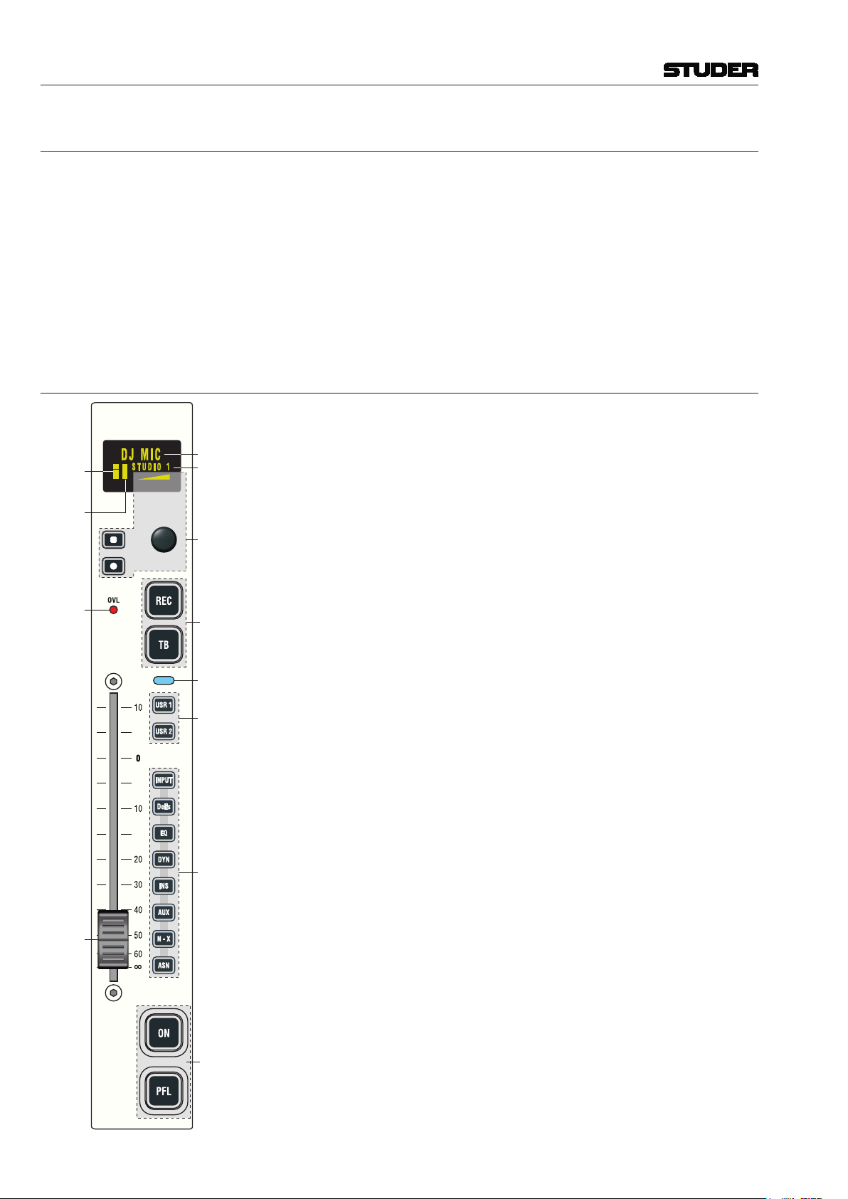
9 The Fader Strip
Channel
Label
T
ext Field
Channel
Rotary
Encoder
Pro-
gramm-
able
Keys
Pro-
gramm-
able
Keys
Channel
Active
User
Keys
Direct
Access
Keys
Level
Meter
Gain
Red.
Meter
(GRM)
Overload
Indicator
Fader
100 mm
(Motor &
Over-
press
Optional)
EveryfaderstripincludesagraphicalOLEDscreenthatcontainsthechannel
label, level and gain reduction meters and parameter readout, selected with the
rotary assign section in the central module. The 100 mm faders can optionally
bemotorized.
A rotary encoder combined with two keys below the display is used to set
channel parameters.
Themainchannelfunctionsareaccessedwithfourlarge,illuminatedkeys:
• REC (record),usedtoassignthechannelsignaldirectlytotherecordbus,
regardless of the fader position, the ON key, and the bus assignment. If
active, the key is illuminated in red.
• TB(talkback).ForN–Xownerchannels,thiskey’sfunctionisTB(talk-
back)totheN–Xreturn.Ifmorethanoneownerisconfiguredtothesame
N–Xoutput,allcorrespondingTB keys work in parallel.
• ON(channelon/off)Pressingthekeytogglesthechannelon/offfunction.
In the audio path, the on/off switch is located after fader and panning.
On status is indicated by illuminating the key.
The function is disabled when the corresponding fader is configured as
master fader for a particular bus.
• PFL(pre-faderlistening)
The purpose of PFL is to feed the pre-fader audio signal of the desired
channelorAUXsend,group,ormaster(program,record)tothePFLbus.
If active, the key is illuminated in yellow.
Twouserkeyscanbeusedforcustomizedfunctionality.
Eight small direct access keys activate the corresponding channel functions
in the main screen for comfortable editing.
More information on operation and configuration: See OnAir 3000 oper-
ating instructions.
OnAir 2500 Digital Mixing Console
Quick Reference Guide 13
Document generated: 09.09.14
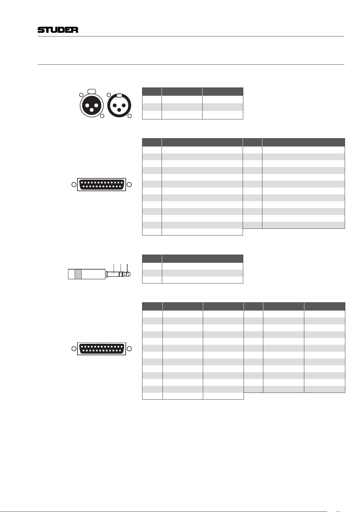
10 Connector Pin Assignments
MIC IN / LINE IN (XLR3f)
LINE OUT 1-8 / CR LSP L/R (XLR3m)
1
3
22
3
1
Pin Signal (Input) Signal (Output)
1 Screen Screen
2 In + Out +
3 In – Out –
LINE OUT 9-16 (25-pinD-type,female)
1
Solder/Crimp View
(or Socket View)
13
25 14
Pin Signal (9-16) Pin Signal (9-16)
1 CH 16 out + 14 CH 16 out –
2 CH 16 out GND 15 CH 15 out +
3 CH 15 out – 16 CH 15 out GND
4 CH 14 out + 17 CH 14 out –
5 CH 14 out GND 18 CH 13 out +
6 CH 13 out – 19 CH 13 out GND
7 CH 12 out + 20 CH 12 out –
8 CH 12 out GND 21 CH 11 out +
9 CH 11 out – 22 CH 11 out GND
10 CH 10 out + 23 CH 10 out –
11 CH 10 out GND 24 CH 9 out +
12 CH 9 out – 25 CH 9 out GND
13 n.c.
GUEST / DJ (Headphones,6.3mmTRSsocket)
TipRingSleeve Pin Signal
Tip Left
Ring Right
Sleeve Screen
AES / EBU IN / OUT (25-pinD-type,female)
1
Solder/Crimp View
(or Socket View)
13
25 14
Pin Signal (1-8) Signal (9-16) Pin Signal (1-8) Signal (9-16)
1 CH 7/8 out + CH 15/16 out + 14 CH 7/8 out – CH 15/16 out –
2 CH 7/8 out scrn CH 15/16 out scrn 15 CH 5/6 out + CH 13/14 out +
3 CH 5/6 out – CH 13/14 out – 16 CH 5/6 out scrn CH 13/14 out scrn
4 CH 3/4 out + CH 11/12 out + 17 CH 3/4 out – CH 11/12 out –
5 CH 3/4 out scrn CH 11/12 out scrn 18 CH 1/2 out + CH 9/10 out +
6 CH 1/2 out – CH 9/10 out – 19 CH 1/2 out scrn CH 9/10 out scrn
7 CH 7/8 in + CH 15/16 in + 20 CH 7/8 in – CH 15/16 in –
8 CH 7/8 in scrn CH 15/16 in scrn 21 CH 5/6 in + CH 13/14 in +
9 CH 5/6 in – CH 13/14 in – 22 CH 5/6 in scrn CH 13/14 in scrn
10 CH 3/4 in + CH 11/12 in + 23 CH 3/4 in – CH 11/12 in –
11 CH 3/4 in scrn CH 11/12 in scrn 24 CH 1/2 in + CH 9/10 in +
12 CH 1/2 in – CH 9/10 in – 25 CH 1/2 in scrn CH 9/10 in scrn
13 n.c. n.c.

OnAir 2500 Digital Mixing Console
14 Quick Reference Guide Document generated: 09.09.14
24V DC IN (10-pinHirose,male)
21 3
98 10
4 7
Pin Signal
1 +22...28 VDC
2 +22...28 VDC
3 n.c. (no internal connection)
4 Power alarm output
5 n.c. (no internal connection)
6 n.c. (no internal connection)
7 n.c. (no internal connection)
8 GND
9 GND
10 Power alarm enable
GPI / GPO 1-16 (37-pinD-type,female;2plugssupplied)
Solder/Crimp View
(or Socket View)
119
37 20
Pin GPI 1-16 GPO 1-16 Pin GPI 1-16 GPO 1-16
1 GPI 1a GPO 1a 20 GPI 1b GPO 1b
2 GPI 2a GPO 2a 21 GPI 2b GPO 2b
3 GPI 3a GPO 3a 22 GPI 3b GPO 3b
4 GPI 4a GPO 4a 23 GPI 4b GPO 4b
5 GPI 5a GPO 5a 24 GPI 5b GPO 5b
6 GPI 6a GPO 6a 25 GPI 6b GPO 6b
7 GPI 7a GPO 7a 26 GPI 7b GPO 7b
8 GPI 8a GPO 8a 27 GPI 8b GPO 8b
9 GPI 9a GPO 9a 28 GPI 9b GPO 9b
10 GPI 10a GPO 10a 29 GPI 10b GPO 10b
11 GPI 11a GPO 11a 30 GPI 11b GPO 11b
12 GPI 12a GPO 12a 31 GPI 12b GPO 12b
13 GPI 13a GPO 13a 32 GPI 13b GPO 13b
14 GPI 14a GPO 14a 33 GPI 14b GPO 14b
15 GPI 15a GPO 15a 34 GPI 15b GPO 15b
16 GPI 16a GPO 16a 35 GPI 16b GPO 16b
17 GND (0 V) GND (0 V) 36 VCC (+5 V) * VCC (+5 V) *
18 GND (0 V) GND (0 V) 37 VCC (+5 V) * VCC (+5 V) *
19 GND (0 V) GND (0 V) * 600 mA max. total
11 Optional External Units
External PSU Anexternal19”/1Upowersupplyunitforquasi-redundantoperationisavail-
able as an option. A 5 m cable for the DC connection is supplied.
Monitoring/Talkback Module For monitoring and talkback in a separate studio, a Monitoring/Talkback
module1.943.444or1.943.447(withoutPFL)canbeconnectedtothecon-
sole.Connectingcablesaresupplied(oneADATandoneCat5cable).
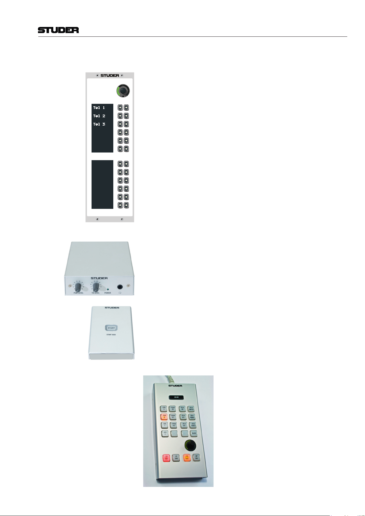
OnAir 2500 Digital Mixing Console
Quick Reference Guide 15
Document generated: 09.09.14
Extended Line (XL) Module TheXLmoduleallowsdirectcommunicationtouptotwelveoutsidesources.
Tel 1
Tel 2
Tel 3
EXTENDED LINE PANEL
PFL TALK
PFL TALK
PFL TALK
It features 12 eight-digit alphanumeric displays for source label indication,
12keyseachforPFLofandTBtotheseindividualdestinations,andarotary
encoder for individual and sum volume control. In a typical application during
e.g. a sports event or elections, communication with many outside locations
needstobecontrolled.TheXLmodulegivesafastandergonomicwayto
fulllingthistask.
Headphones Amplier Box Thiscompactheadphonesampcanbettedontopoforunderatablewith
respective mounting brackets, next to a guest. It may be connected directly to
alineoutputoftheconsoleandfeaturesalocalamplierwithvolumecontrol.
In addition a talkback signal with separate volume control can be enabled
and brought to the guest headphones, heard in split mode and controlled via
a GPO signal.
GPIO Boxes Two types of general-purpose desktop boxes in the OnAir 2500 design, both
withanilluminatedkey, and oneofthemwiththreeadditional LEDs are
available for many different applications, e.g. cough key, control of external
devices,etc.ThekeysmaydirectlybeconnectedtoGPIs,theLEDstoGPOs,
andconguredfortherespectivetaskinthecongurationmenu.
Compact Monitoring/TB Module: The compact monitoring/TB box offers an array
of configurable keys for monitoring source
selection and talkback destinations, red light
indication, and studio loudspeaker/headphone
control. Talkback between any locations is pos-
sible, as well as to external lines, the master,
AUX,andN–Xoutputs,butneedstobecong-
ured as desired.
OnAir 2500 Digital Mixing Console
16 Quick Reference Guide Document generated: 09.09.14
Studio Source Selection SelectionofthestudiomonitoringsourcecanbedoneontheCRdeskoron
the compact monitoring/TB box.
Studio Muting The studio monitoring speakers are automatically muted if at least one of the
microphonesinthestudio(Conguration:InputLocation=Studio2)ison.
The studio headphones are not muted in such a case.
Talkback DuringtalkbackfromstudiotoCRandviceversa,thestudiospeakerlevel
isautomaticallydimmed.ThetalkbacksignalfromCRtostudio isnot
dimmed and has the normal listening level on both the studio speakers and
headphones.
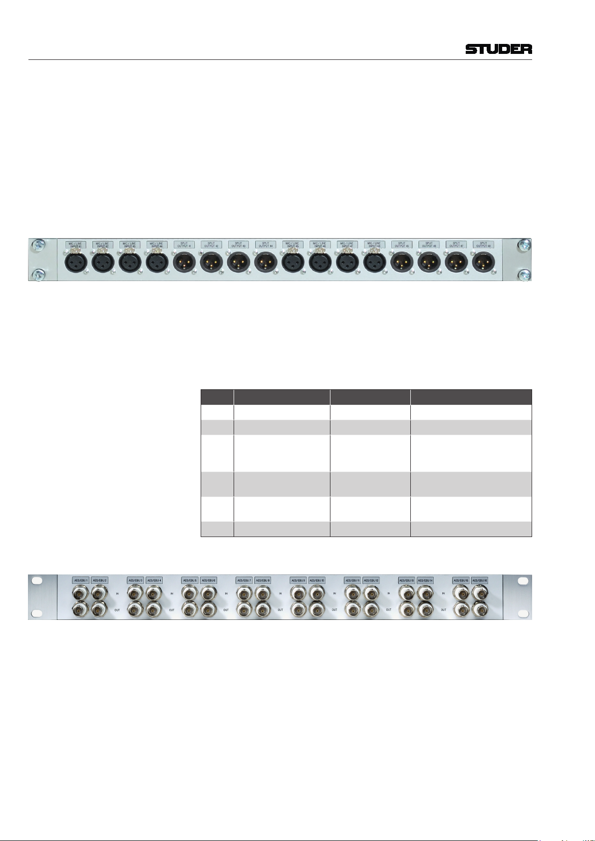
XLR Break-Out Box
Thisboxisimplementedasacongurable,modularsystem.Theemptybox
(A949.0580)canbeequippedwithdifferentoptionsfortheleftandrightpart.
Thepictureaboveshowsabreak-outboxequippedwithtwooptionsno.3
formicrophoneinputs(2×4XLR3f)andthecorrespondingsplitoutputs
(2x4XLR3m).Ontherearoftheboxtwo25-pinD-typesockets(f)are
providedforconnectiontothecard(s).Formatchingcablesrefertothetable
at the end of this chapter. All connectors can be custom-labeled.
Available Options Option Description Order no. Remarks
18 × XLR f to 1 × DB25 f A949.0581 for 1 × Line input
28 × XLR m to 1 × DB25 f A949.0582 for 1 × Line output
34 × XLR f / 4 × XLR m
to 1 × DB25 f A949.0583
for 1 × Mic input/Split output
or 1 × Mic Insert send/return
or 1 × AES/EBU input/output
48 × XLR f to 2 × DB25 f A949.0584 for 2 × Mic input
or 2 × AES/EBU input
54 × XLR f to 1 × DB25 f,
4 × blank cover A949.0585 for 1 × Mic input
or 1 × AES/EBU input
68 × blank cover 8 × C031.030111
AES/EBU on BNC Break-Out Box (orderno.A949.0586)
This19”/1Ubox allowsconvertingAES/EBUsignalsfrom balancedto
unbalancedonBNCconnectorsandvice-versa.Eachconnectorpair(inand
out)canbecustom-labeledwithaninlaylabel.Ontherearoftheboxfour
25-pinD-typesockets(f)areprovidedforconnectiontotheAES/EBUcards.
For matching cables refer to the table at the end of this chapter. All connec-
tors can be custom-labeled. Maximum cable lengths are 10 m for the D-type
cables,and100mfortheBNCcables.
GPIO Break-Out Box (orderno.A949.0588)

OnAir 2500 Digital Mixing Console
Quick Reference Guide 17
Document generated: 09.09.14
For easier wiring of single GPI and/or GPO signals, this break-out box can
be used. 16 GPI signals and 12 of the 16 GPO signals of a GPIO card with
relayoutputs(A949.0436)arewiredtosingle,4-pin‘Combicon’terminals
(seebelow),providingtherelaycontactsoropto-couplerinputs,aswellas
GNDandashortcircuit-proof5VDCsupply.
If voltages exceeding 50 V (AC or DC) are switched, the break-out box must
be placed within a closed rack in order to avoid shock hazards by touching
the contacts.
Fourofthe16GPOsignals(GPO1...4,marked in black on the front panel)
are connected to solid-state relays whose power terminals are wired to the
‘Combicon’ terminals.These powercontactscanswitchAC loadsfrom
24...240 V with a maximum total current of 5 A over all 4 relays.
For safety reasons, these four terminals have no additional GND and 5 V
supply. All remaining low-voltage terminals (GPI 1...16, GPO 5...16) are
coded on pin #4 in order to prevent high-voltage connectors being inserted
by mistake.
The high-voltage connectors must be coded, as shown below; six coding
elements (order no. C054.251100) are included with the break-out box.
Coding Element
Eight4-pin ‘Combicon’ plugswithscrewterminals(C054.251104)are
includedwiththebreak-out box.Ifmoreplugsare required, pleaseorder
separately.Ontherearoftheboxtwo37-pinD-typesockets(f)areprovided
for connection to the GPIO card. For matching cables please refer to the table
below.
Pin Assignment
Pin
GPO 1...4 (Outputs)
(upper row, Sockets
UNcoded/Plugs coded)
GPO 5...16 (Outputs)
(upper row, *Sockets
coded/Plugs UNcoded)
GPI 1...16 (Inputs)
(lower row, *Sockets
coded/Plugs UNcoded)
Socket View
1 2 3 4
*1 n.c. +5 V +5 V
2 n.c. GND GND
3 Solid-State Relay, Contact 1 GPO Relay, Contact 1 Optocoupler Input 1
4 Solid-State Relay, Contact 2 GPO Relay, Contact 2 Optocoupler Input 2
Cables for Break-Out Boxes Description Length [m] Order no.
DB25 m-m 1:1 cable, 8 × shielded 0.45 C089.201161
DB25 m-m 1:1 cable, 8 × shielded 0.9 C089.201174
DB25 m-m 1:1 cable, 8 × shielded 1.5 C089.201170
DB37 m-m 1:1 cable 0.9 C089.201178

OnAir 2500 Digital Mixing Console
18 Quick Reference Guide Document generated: 09.09.14

Disclaimer
The information in this document has been carefully checked and is believed to be accurate at the time of publica-
tion.However,noresponsibilityistakenbyusforinaccuracies,errors,oromissions,norisanyliabilityassumedfor
any loss or damage resulting either directly or indirectly from use of the information contained within it.
Preparedandeditedby CopyrightbyStuderProfessionalAudioGmbH
StuderProfessionalAudioGmbH PrintedinSwitzerland
TechnicalDocumentation Orderno.5053946(0914)
Althardstrasse 30
CH-8105Regensdorf–Switzerland
http://www.studer.ch Subjecttochange
StuderisaregisteredtrademarkofStuderProfessionalAudioGmbH,Regensdorf
Other manuals for OnAir 2500
2
Table of contents
Other Studer Dj Equipment manuals

Popular Dj Equipment manuals by other brands

KAM
KAM DMX Laser80 FScan instruction manual

American DJ
American DJ HMI 575TM User instructions

Petra electric
Petra electric PerlFit PF 15 Instructions for use

Pioneer
Pioneer DDJ-RX operating instructions

Acclaim Lighting
Acclaim Lighting Aria Wireless DMX user guide

thomann
thomann Stairville LED Par 64 COB user manual


