Studer Xtender XTH 3000-12 User manual

STUDER In
n
51L
Xt
e
bat
t
User
XT
H
XT
H
XT
H
XT
H
Tem
p
Co
m
n
otec 2009 –
e
nd
e
t
ery
c
man
u
H
3
0
H
5
0
H
6
0
H
8
0
p
erat
u
m
man
d
V3.1.0
e
r,
c
har
g
u
al
0
00
-
0
00
-
0
00
-
4
0
00
-
4
u
re se
d
mo
d
Unit
g
er a
-
12
-
24
-
4
8
-
4
8
nsor
d
ule
co
nd tr
a
X
X
X
X
X
X
mbi
n
a
nsf
e
X
T
M
X
T
M
X
T
M
X
T
M
X
T
M
X
T
M
B
T
S
RC
M
n
ing
e
r sy
s
M
15
0
M
20
0
M
24
0
M
35
0
M
26
0
M
40
0
S
-0
1
M
-0
1
inv
e
s
tem.
0
0-
1
0
0-
1
0
0-
2
0
0-
2
0
0-
4
0
0-
4
1
1
e
rter,
1
2
1
2
2
4
2
4
4
8
4
8


STUDER Innotec
Xtender
User manual V.3.1.0 1
SUMMARY
1INTRODUCTION...................................................................................................................................3
2GENERAL INFORMATION....................................................................................................................3
2.1Operating instructions.......................................................................................................................3
2.2Conventions.......................................................................................................................................4
2.3Quality and warranty........................................................................................................................4
2.3.1Exclusion of warranty....................................................................................................................4
2.3.2Exclusion of liability........................................................................................................................5
2.4Warnings and notes..........................................................................................................................5
2.4.1General...........................................................................................................................................5
2.4.2Precautions for using the batteries.............................................................................................6
3ASSEMBLY AND INSTALLATION...........................................................................................................6
3.1Handling and moving.......................................................................................................................6
3.2Storage................................................................................................................................................6
3.3Unpacking..........................................................................................................................................6
3.4Installation site....................................................................................................................................6
3.5Fastening.............................................................................................................................................7
3.5.1Fastening XTH model....................................................................................................................7
3.5.2Fastening XTM model ...................................................................................................................7
3.6Connections.......................................................................................................................................7
3.6.1General recommendations ........................................................................................................7
3.6.2Device connection compartment.............................................................................................9
4CABLING ...........................................................................................................................................10
4.1Choice of system.............................................................................................................................11
4.1.1Hybrid type stand-alone systems..............................................................................................11
4.1.2Grid-connected emergency systems......................................................................................11
4.1.3Integrated mobile systems ........................................................................................................11
4.1.4Multi-unit systems.........................................................................................................................11
4.2Earthing system................................................................................................................................11
4.2.1Mobile installation or installation connected to the grid via plug connector ..................12
4.2.2Stationary installation .................................................................................................................12
4.2.3Installation with automatic PE-neutral switching ...................................................................12
4.3Recommendations for dimensioning the system.......................................................................13
4.3.1Dimensioning the battery..........................................................................................................13
4.3.2Dimensioning the inverter..........................................................................................................13
4.3.3Dimensioning the generator .....................................................................................................13
4.3.4Dimensioning the renewable energy sources........................................................................13
4.4Wiring diagrams...............................................................................................................................14
4.5Connecting the battery.................................................................................................................14
4.5.1Battery cable cross-section and DC protective devices.....................................................14
4.5.2Connecting the battery (Xtender side)...................................................................................15
4.5.3Fuse mounting on battery positive pole (XTM only)..............................................................15
4.5.4Battery-side connection ............................................................................................................15
4.5.5Earthing the battery....................................................................................................................16
4.5.6Connecting the consumers at the 230 V AC output ............................................................16
4.5.7Connecting the AC supply sources.........................................................................................17
4.5.8Wiring auxiliary contacts............................................................................................................17
4.5.9Connecting the communications cables...............................................................................17
4.5.10Connecting the temperature sensor (BTS-01)....................................................................17
4.5.11Connecting the remote command module RCM10 (XTM only)....................................18
5POWERING UP THE INSTALLATION....................................................................................................18
6DESCRIPTION AND FUNCTIONING...................................................................................................19
6.1Circuit diagram................................................................................................................................19
6.2Description of the main functions.................................................................................................19
6.2.1Inverter..........................................................................................................................................19
6.2.2Automatic load detection ........................................................................................................20
6.2.3Transfer relay................................................................................................................................20

STUDER Innotec
Xtender
2 V.3.1.0 User manual
6.2.4Battery charger...........................................................................................................................21
6.2.5Limiting the input current by limiting the charger current....................................................22
6.2.6The inverter as source backup (“smart boost” function) .....................................................23
6.2.7Input current controlled by input voltage...............................................................................23
6.2.8Battery protection.......................................................................................................................24
6.2.9Xtender protection .....................................................................................................................24
6.2.10Auxiliary contacts ...................................................................................................................24
6.2.11The real time clock.................................................................................................................25
6.2.12Entry command (Remote control on/off) ..........................................................................25
6.3Multi-unit configurations.................................................................................................................25
6.3.1Three-phase system....................................................................................................................26
6.3.2Increasing the power by paralleling units...............................................................................26
6.3.3Combined system.......................................................................................................................27
6.4Accessories.......................................................................................................................................27
6.4.1Control centre and RCC-02/03 (remote control) display ....................................................27
6.4.2BTS-01 temperature sensor.........................................................................................................28
6.4.3Remote command Module RCM-10......................................................................................28
7CONTROL ..........................................................................................................................................29
7.1Main on/off control.........................................................................................................................29
7.2Display and control panel..............................................................................................................29
8MAINTENANCE OF THE INSTALLATION.............................................................................................31
9PRODUCT RECYCLING......................................................................................................................31
10EC DECLARATION OF CONFORMITY................................................................................................32
11COMMENTS OF ANNEXES’ FIGURES.................................................................................................33
12FIGURE’S ELEMENTS (DC PART).........................................................................................................35
13FIGURE ELEMENT'S (AC PART)...........................................................................................................36
14ELEMENTS OF CONNEXION CABINET (FIG 4A)................................................................................37
15CONTROL AND DISPLAY PARTS FOR THE XTENDER (FIG. 4B) ..........................................................38
16MODEL IDENTIFICATION (FIG. 1B)....................................................................................................39
17TABLE OF STANDARD CONFIGURATIONS.........................................................................................40
18TECHNICAL DATA – XTH....................................................................................................................42
19TECHNICAL DATA – XTM...................................................................................................................44
20NOTES................................................................................................................................................46

STUDER Innotec
Xtender
User manual V.3.1.0 3
1INTRODUCTION
Congratulations! You are about to install and use a device from the Xtender range. You have
chosen a high-tech device that will play a central role in energy saving for your electrical
installation. The Xtender has been designed to work as an inverter / charger with advanced
functions, which can be used in a completely modular way and guarantee the faultless functioning
of your energy system.
When the Xtender is connected to a generator or network, the latter directly supplies the
consumers, and the Xtender works like a battery charger and backup device if necessary. The
powerful battery charger has an exceptional high efficiency and power factor correction (PFC)
close to 1. It guarantees excellent battery charging in all situations. The charge profile is freely
configurable according to the type of battery used or the method of usage. The charge voltage is
corrected depending on the temperature, thanks to the optional external sensor. The power of the
charger is modulated in real time dependent according to the demand of the equipment
connected at the Xtender output and the power of the energy source (network or generator). It
can even temporarily backup the source if the consumer demand exceeds the source capacity.
The Xtender continuously monitors the source to which it is connected (network or generator) and
disconnects itself immediately if the source is missing, disturbed or does not correspond to the
quality criteria (voltage, frequency, etc.). It will then function in independent mode, thanks to the
integrated inverter. This inverter, which has an extremely robust design, benefits from STUDER
Innotec’s many years of experience and expertise in this area. It could supply any type of load
without faults, enjoying reserves of additional power that is unmatched on the market. All your
equipment will be perfectly provided with energy and protected from power outages in systems
where energy supply is unpredictable (unreliable network) or voluntarily limited or interrupted, such
as hybrid installations on remote sites or mobile installations.
The parallel and/or three-phase network operation of the Xtender offers modularity and flexibility
and enables optimum adaptation of your system to your energy requirements.
The RCC-02/03 control, display and programming centre (optional) enables optimum configuration
of the system and guarantees the operator continuous control for all important configurations in
the installation.
In order to guarantee perfect commissioning and functioning of your installation, please read this
manual carefully. It contains all the necessary information relating to the functioning of the inverters
/ chargers in the Xtender series. The setting up of such a system requires special expertise and may
only be carried out by qualified personnel familiar with the applicable local regulations.
2GENERAL INFORMATION
2.1 OPERATING INSTRUCTIONS
This manual is an integral part of each inverter/charger from the Xtender series.
It covers the following models and accessories1:
Inverter/charger: XTH 3000-12 – XTH 5000-24 – XTH 6000-48 – XTH 8000-48
Inverter/charger: XTM 1500-12, XTM 2000-12, XTM 2400-24,
XTM 3500-24, XTM 2600-48, XTM 4000-48
Temperature sensor: BTS-01
Remote command module: RCM-10
For greater clarity, the device is referred to in this manual as Xtender, unit or device, when the
description of its functioning applies indiscriminately to different Xtender models.
These operating instructions serve as a guideline for the safe and efficient usage of the Xtender.
Anyone who installs or uses an Xtender can rely completely on these operating instructions, and is
bound to observe all the safety instructions and indications contained. The installation and
commissioning of the Xtender must be entrusted to a qualified professional. The installation and
1Also for 120Vac model (-01)
STUDER Innotec
Xtender
4 V.3.1.0 User manual
usage must conform to the local safety instructions and applicable standards in the country
concerned.
2.2 CONVENTIONS
This symbol is used to indicate the presence of a dangerous voltage that is sufficient to
constitute a risk of electric shock.
This symbol is used to indicate a risk of material damage.
This symbol is used to indicate information that is important or which serves to optimise
your system.
All values mentioned hereafter, followed by a configuration no. indicate that this value may be
modified with the help of the RCC-02/03 remote control.
In general, the default values are not mentioned and are replaced by a configuration no. in the
following format: {xxxx}. The default values for this configuration are specified in the configuration
table, p. 40.
All configuration values modified by the operator or installer must be transferred into the
same table. If a parameter not appearing in the list (advanced configurations) has been
modified by an authorised person with technical knowledge, they will indicate the
number of the modified parameter(s), the specifications of the configuration(s) and the
new value set, at the end of the same table.
All figures and letters indicated in brackets refer to items of figures in the separate manual
“Appendix to the installation and operating instructions” supplied with the device.
The figures in brackets refer to elements belonging to the Xtender.
The uppercase letters in brackets refer to AC cabling elements.
The lowercase letters in brackets refer to battery cabling elements.
2.3 QUALITY AND WARRANTY
During the production and assembly of the Xtender, each unit undergoes several checks and tests.
These are carried out with strict adherence to the established procedures. Each Xtender has a
serial number allowing complete follow-up on the checks, according to the particular data for
each device. For this reason it is very important never to remove the type plate (appendix I – fig.
3b) which shows the serial number. The manufacture, assembly and tests for each Xtender are
carried out in their entirety by our factory in Sion (CH). The warranty for this equipment depends
upon the strict application of the instructions appearing in this manual.
The warranty period for the Xtender is 2 years.
2.3.1 Exclusion of warranty
No warranty claims will be accepted for damage resulting from handling, usage or processing that
does not explicitly appear in this manual. Cases of damage arising from the following causes are
notably excluded from the warranty:
Surge voltage on the battery input (for example, 48 V on the battery input of an XTH 3000-12)
Incorrect polarity of the battery
The accidental ingress of liquids into the device or oxidation resulting from condensation
Damage resulting from falls or mechanical shocks
Modifications carried out without the explicit authorisation of Studer Innotec
Nuts or screws that have not been tightened sufficiently during the installation or maintenance
Damage due to atmospheric surge voltage (lightning)

STUDER Innotec
Xtender
User manual V.3.1.0 5
Damage due to inappropriate transportation or packaging
Disappearance of original marking elements
2.3.2 Exclusion of liability
The placement, commissioning, use, maintenance and servicing of the Xtender cannot be the
subject of monitoring by Studer Innotec. For this reasons we assume no responsibility and liability for
damage, costs or losses resulting from an installation that does not conform to the instructions,
defective functioning or deficient maintenance. The use of a Studer Innotec inverter is the
responsibility of the customer in all cases.
This equipment is neither designed nor guaranteed to supply installations used for vital medical
care nor any other critical installation carrying significant potential damage risks to people or the
environment.
We assume no responsibility for the infringement of patent rights or other rights of third parties that
result from using the inverter.
Studer Innotec reserves the right to make any modifications to the product without prior
notification.
2.4 WARNINGS AND NOTES
2.4.1 General
This manual is an integral part of the device and must be kept available for the operator
and installer. It must remain close to the installation so that it may be consulted at any
time.
The configuration table available at the end of the manual (p. 40) must be kept up to date in the
event of modification of the configurations by the operator or installer. The person in charge of
installation and commissioning must be wholly familiar with the precautionary measures and the
local applicable regulations.
When the Xtender is running, it generates voltage that can be potentially lethal. Work on
or close to the installation must only be carried out by thoroughly trained and qualified
personnel. Do not attempt to carry out ongoing maintenance of this product yourself.
The Xtender or the generator connected to it may start up automatically under certain
predetermined conditions.
When working on the electrical installation, it is important to be certain that the source of
DC voltage coming from the battery as well as the source of AC voltage coming from a
generator or network have been disconnected from the electrical installation.
Even when the Xtender has been disconnected from the supply sources (AC and DC), a
dangerous voltage may remain at the outputs. To eliminate this risk you must switch the
Xtender OFF using the ON/OFF button (1). After 10 seconds the electronics is discharged
and intervention may take place without any danger.
All elements connected to the Xtender must comply with the applicable laws and regulations.
Persons not holding written authorisation from Studer Innotec are not permitted to proceed with
any change, modification or repairs that may be required. Only original parts may be used for
authorised modifications or replacements.
This manual contains important safety information. Read the safety and working instructions
carefully before using the Xtender. Adhere to all the warnings given on the device as well as in the
manual, by following all the instructions with regard to operation and use.
The Xtender is only designed for indoor use and must under no circumstances be subjected to rain,
snow or other humid or dusty conditions.
The maximum specifications of the device shown on the type plate, as at fig. 1b, must be adhered
to.

STUDER Innotec
Xtender
6 V.3.1.0 User manual
In the event of use in motorised vehicles, the Xtender must be protected from dust, splash water
and any other humid condition. It must also be protected from vibration by installing absorbent
parts.
2.4.2 Precautions for using the batteries
Lead-acid or gel batteries produce a highly explosive gas with normal use. No source of sparks or
fire should be present in the immediate vicinity of the batteries. The batteries must be kept in a well-
ventilated place and be installed in such a way as to avoid accidental short-circuits when
connecting.
Never try to charge frozen batteries.
When working with the batteries, a second person must be present in order to lend assistance in the
event of problems.
Sufficient fresh water and soap must be kept to hand to allow adequate and immediate washing
of the skin or eyes affected by accidental contact with the acid.
In the event of accidental contact of the eyes with acid, they must be washed carefully with cold
water for 15 minutes. Then immediately consult a doctor.
Battery acid can be neutralised with baking soda. A sufficient quantity of baking soda must be
available for this purpose.
Particular care is required when working close to the batteries with metal tools. Tools such as
screwdrivers, open-ended spanners, etc. may cause short-circuits. Consequently occurring sparks
may cause the battery to explode.
When working with the batteries, all metal jewellery such as rings, bracelet watches, earrings, etc.,
must be taken off. The current output by the batteries during a short-circuit is sufficiently powerful to
melt the metal and cause severe burns.
In all cases, the instructions of the battery manufacturer must be followed carefully.
3ASSEMBLY AND INSTALLATION
3.1 HANDLING AND MOVING
The weight of the Xtender is between 35 and 50kg depending upon the model. Use an appropriate
lifting method as well as help from a third party when installing the equipment.
3.2 STORAGE
The equipment must be stored in a dry environment at an ambient temperature of between
-20°C and 60°C. It stays in the location where it is to be used a minimum of 24 hours before being
set up.
3.3 UNPACKING
When unpacking, check that the equipment has not been damaged during transportation and
that all accessories listed below are present. Any fault must be indicated immediately to the
product distributor or the contact given at the back of this manual.
Check the packaging and the Xtender carefully.
Standard accessories:
Installation and operating instructions, c.f. Appendix 1
Mounting plate – fig. 2a (18)
2 conduit glands for the battery cable
3.4 INSTALLATION SITE
The installation site for the Xtender is of particular importance and must satisfy the following criteria:
Protected from any unauthorised person.
Protected from water and dust and in a place with no condensation.

STUDER Innotec
Xtender
User manual V.3.1.0 7
It must not be situated directly above the battery or in a cabinet with it.
No easily inflammable material should be placed directly underneath or close to the Xtender.
Ventilation apertures must always remain clear and be at least 15cm from any obstacle that may
affect the ventilation of the equipment according to fig. 2b.
In mobile applications it is important to select an installation site that ensures as low a vibration level
as possible.
3.5 FASTENING
The Xtender is a heavy unit and must be mounted to a wall designed to bear such a
load. A simple wooden panel is insufficient.
The Xtender must be installed vertically with sufficient space around it to guarantee adequate
ventilation of the device (see figs. 2a and 2b).
3.5.1 Fastening XTH model
Firstly fix the mounting bracket (18)) supplied with the device using 2 Ø < 6-8 mm >screws**.
Then hang the Xtender on the bracket. Fasten the unit permanently using 2 Ø <6-8 mm> screws**
on to the two notches located at the underside of the case.
3.5.2 Fastening XTM model
Screw on a solid wall (concrete or metallic wall) an M8 screw without washer up to a distance of
1.6 mm of the wall.
Hang the apparatus by having care to release beforehand the trap door of access (17) by
inserting it inside the apparatus using a screwdriver, if you estimate that a complete tightening of
this point of fixing is necessary. In theory complete tightening is necessary only in the mobile
installations.
Dismount the lower plastic cap of the apparatus giving access to the compartment of wiring.
Carefully fix the apparatus with two screws (Ø 6-8 mm) in the two clamp holes (16) inside the
compartment of wiring.
If the Xtender is installed in a closed cabinet this must have sufficient ventilation to guarantee an
ambient temperature that conforms to the operation of the Xtender.
**: These items are not delivered with the device.
It is imperative to ensure complete and safe fastening of the device. A device that is
simply hung may detach and cause severe damage.
In motor vehicles or when the support may be subject to strong vibrations, the Xtender must be
mounted on anti-vibration supports.
3.6 CONNECTIONS
3.6.1 General recommendations
The Xtender falls within protection class I (has a PE connection terminal). It is vital that a protective
earth is connected to the AC IN and/or AC OUT PE terminals. An additional protective earth is
located between the two fastening screws at the bottom of the unit (fig. 2b-(17)).

STUDER Innotec
Xtender
8 V.3.1.0 User manual
In all cases, the PE conductor for the equipment must at least be connected to the PE
for all equipment in protection class I upstream and downstream of the Xtender
(equipotential bonding). It is mandatory that the legislation in force for the application
concerned be adhered to.
Tighten of the input (13) and output (14) terminals by means of a no. 3 screwdriver and those for
the “REMOTE ON/OFF” (7) and “AUX.CONTAC” (8) by means of a no. 1 screwdriver.
The cable sections of these terminals must conform to local regulations.
All connection cables as well as the battery cables must be mounted using cable restraints in order
to avoid any traction on the connection.
Battery cables must also be as short as possible and the section must conform with the applicable
regulations and standards. Sufficiently tighten the clamps on the “battery” inputs (fig. 4a (11) and
(12)).

STUDER Innotec
Xtender
User manual V.3.1.0 9
3.6.2 Device connection compartment
The unit’s connection compartment must remain permanently closed when in operation.
It is imperative to close the protection cap on the connection terminals after each
intervention in the device.
After opening, check that all sources of AC and DC voltage (batteries) have been
disconnected or put out of service.

STUDER Innotec
Xtender
10 V.3.1.0 User manual
Pos. Denomination Description Comment
1 ON/OFF
Main switch
Main on/off switch
See chapter 7.1 - p 29.
In XTM series, this function is deported on
the remote command module RCM-10.
See chap.6.4.3 – p.28
2 Temp. Sens
Connector for the battery
temperature sensor See chapter 6.4.2 – p. 28.
Only connect the original Studer BTS-01
sensor
3 Com. Bus
Double connector for
connecting peripherals such as
the RCC002/03 or other
Xtender units
See chapter 4.5.9 – p. 17.
The two termination switches (4) for the
communication bus both remain in
position T (terminated) except when
both connectors are in use.
4 O / T
(Open /
Terminated)
Switch for terminating the
communication bus.
5 --
3.3 V (CR-2032) lithium ion type
battery socket Used as a permanent supply for the
internal clock. See chapter The real time
clock 6.2.11 - p 25.
6 --
Jumper for programming the
off/on switch by dry contact See chapter 6.2.12 – p. 24 and fig. 8b
point (6) and (7). They are positioned at
A-1/2 and B-2/3 by default
7 REMOTE
ON/OFF
Entry command terminals..
In XTM series, this entry is
deported on the remote
command module RCM-10.
See chap. 6.4.3 – p. 28
Allow to dive a function – to be defined
by programming – by the closing of a dry
contact or by the presence of a voltage
across these terminals. See chapter
6.2.12– p. 24).
8 AUXILLARY
CONTACT
Auxiliary contact (See chapter 6.2.10– p. 24)
Take care not to exceed the admissible
loads
9 --
Activation indicators for
auxiliary contacts 1 and 2 See chapter 6.2.10– p. 24
10 L1/L2/L3
Phase selection jumpers. See chapter 6.3.1. – p.26.
Jumper default at position L1
11 +BAT
Positive pole battery
connection terminals Carefully read chapter 4.5 – p.14
Take care with the polarity of the battery
and when tightening the clamp.
12 -BAT
Negative pole battery
connection terminals
13 AC Input
Connection terminals for the
alternative power supply
(generator or public network)
See chapter 4.5.7 - p. 17.
Note: It is imperative that the PE terminal
be connected.
14 AC Output
Connection terminals for the
device output. See chapter 4.5.6 - p. 17.
Note: Increased voltages may appear
on the terminals, even in the absence of
voltage at the input of the inverter.
15 RCM-10 Connector for RCM-10 module Only on XTM. See chap. 6.4.3 – p.28
4CABLING
The connection of the Xtender inverter / charger is an important installation step.
It may only be carried out by qualified personnel and in accordance with the applicable local
regulations and standards. The installation must always comply with these standards.
Pay attention that connections are completely tightened and that each wire is connected at the
right place.
STUDER Innotec
Xtender
User manual V.3.1.0 11
4.1 CHOICE OF SYSTEM
The Xtender may be used in different system types, each of which must meet the standards and
particular requirements associated with the application or site of installation. Only an appropriately
qualified installer can advise you effectively on the applicable standards with regard to the various
systems and the country concerned.
Examples of cabling are presented in appendix I of this manual, fig. 5 and following. Please
carefully read the notes associated with these examples in the tables on p. 33 and following.
4.1.1 Hybrid type stand-alone systems
The Xtender can be used as a primary supply system for grid-remote sites where a renewable
energy source (solar or hydraulic) is generally available and a generator is used as backup. In this
case, batteries are generally recharged by a supply source such as solar modules, wind power or
small hydropower systems. These supply sources must have their own voltage and/or current
regulation system and are connected directly to the battery. (Example, fig. 11)
When the energy supply is insufficient, a generator is used as a back-up energy source. This allows
the batteries to be recharged and direct supply to consumers via the Xtender transfer relay.
4.1.2 Grid-connected emergency systems
The Xtender can be used as an emergency system, also known as an uninterruptible power supply
(UPS) – enabling a reliable supply to a site connected to an unreliable network. In the event of an
interruption to the energy supply from the public network, the Xtender, connected to a battery,
substitutes the faulty source and enables a support supply to the users connected downstream.
These will be supplied as long as the energy stored in the battery allows. The battery will quickly be
recharged at the next reconnection to the public grid.
Various application examples are described in figs. 8a – 8c in appendix I.
The use of the Xtender as a UPS must be carried out by qualified personnel who have
been checked by the responsible local authorities. The diagrams in the appendix are
given for information and as a supplement. The applicable local standards and
regulations must be adhered to.
4.1.3 Integrated mobile systems
These systems are meant to be temporarily connected to the grid and ensure the supply of the
mobile system when this is disconnected from the grid. The main applications are for boats, service
vehicles and leisure vehicles. In these cases, two separate AC inputs are often required, one
connected to the grid and the other connected to an on-board generator. Switching between
two sources must be carried out using an automatic or manual reversing switch, conforming to the
applicable local regulations. The Xtender has a single AC input.
Various application examples are described in figs. 10a – 10b – 10c).
4.1.4 Multi-unit systems
Whatever system is selected, it is possible to realise systems composed of several units of the same
type and the same power output. Up to three Xtenders in parallel or three extenders forming a
three-phase grid or three times two or three Xtenders in parallel forming a three-phase / parallel
grid, may be thus combined.
4.2 EARTHING SYSTEM
The Xtender is a protection class I unit, which is intended for cabling in a grid type TT, TN-S or TNC-S.
The earthing of the neutral conductor (E) is carried out at a sole installation point, upstream of the
RCD circuit breaker (D).
STUDER Innotec
Xtender
12 V.3.1.0 User manual
The Xtender can be operated with any earthing system. In all cases it is imperative that the
protective earth be connected in compliance with the applicable standards and regulations. The
information, notes, recommendations and diagram mentioned in this manual are subject to local
installation regulations in every case. The installer is responsible for the conformity of the installation
with the applicable local standards.
4.2.1 Mobile installation or installation connected to the grid via plug
connector
When the input of the device is connected directly to the grid via a plug, the length of the cable
must not exceed 2 m and the plug must remain accessible.
In the absence of voltage at the input, the neutral and live are interrupted, thereby guaranteeing
complete isolation and protection of the cabling upstream of the Xtender.
The earthing system downstream of the Xtender is determined by the upstream earthing system
when the grid is present. In the absence of the grid, the earthing system downstream of the inverter
is in isolated mode. The safety of the installation is guaranteed by the equipotential bonding.
The connection (link) between the neutrals (C) upstream and downstream of the
Xtender is not permitted in this configuration.
This connection type guarantees the optimal continuity for supplying the Xtender loads. The first
isolation fault will not lead to an interruption in the supply.
If the installation requires the use of a permanent isolation controller this would have to be de-
activated when the TT network is present at the Xtender input.
All sockets and protection class I devices connected downstream of the Xtender must
be properly connected to the earth (earthed socket). The cabling rules above remain
valid, including in installations, in all cases where the Xtender input is connected to the
grid via a plug connector.
4.2.2 Stationary installation
The installation may be equivalent to a mobile installation (with interrupted neutral).
In a fixed installation where the neutral is connected to the earth at a single installation point
upstream of the Xtender, it is permissible to carry out a connection of the neutrals in order to
preserve an unchanged earthing system downstream, independent of the operating mode of the
Xtender. This choice has the advantage of keeping the protection devices downstream of the
Xtender. This connection can be executed according to the examples in appendix 1, or carried
out by modifying the configuration {1486}
In this case the appearance of the first fault will lead to the installation stopping or the
disconnection of the protection devices upstream and/or downstream of the Xtender.
Safety is guaranteed by the equipotential bonding and by any RCD circuit-breakers placed
downstream.
This connection (C) is not permitted if a socket is installed upstream of the Xtender.
4.2.3 Installation with automatic PE-neutral switching
In certain applications, it is desirable to keep the neutral upstream and downstream of the Xtender
separated (C) while re-establishing the earthing system (TN-S, TT or TNC-S) in the absence of voltage
at the input. This can be programmed by the configuration {1485} via the RCC-02/03 remote
control. This modification must be carried out possessing technical knowledge, at the responsibility
of the installer and in conformity with the applicable regulations and standards.
This allows adherence to the requirements for an earth-neutral connection at the source.

STUDER Innotec
Xtender
User manual V.3.1.0 13
4.3 RECOMMENDATIONS FOR DIMENSIONING THE SYSTEM
4.3.1 Dimensioning the battery
The battery capacity is dimensioned according to the requirements of the user – that is 5 to 10
times its average daily consumption. The discharge depth of the battery will therefore be limited
and the service life of the battery will be extended.
On the other hand, the Xtender must have a battery capacity that is large enough to be able to
take full advantage of the performance of the equipment. The minimum capacity of the batteries
(expressed in Ah) is generally dimensioned in the following way: five times the rated power output
of the Xtender / the battery voltage. For example, the model XTH 8048 must have a battery of a
minimum capacity of 7000*5/48=730 Ah (C 10). Because of the inverter’s extreme overload
capacity, it is often recommended that this value be rounded up. An under-dimensioned battery
may lead to an accidental and undesired stopping of the Xtender in the event of high instances of
use. This stoppage will be due to a voltage that is insufficient on the battery, subject to a strong
discharge current.
The battery will be selected with regard to the greatest value resulting from the calculations set out
above.
The battery capacity determines the adjustment of the configuration {1137} “battery charge
current”. A value between 0.1 and 0.2 x C batt. [Ah] (C10) enables an optimum charge to be
guaranteed.
The method proposed below is strictly indicative and in no way constitutes a guarantee
of perfect dimensioning. The installer is solely responsible for good dimensioning and
installation
4.3.2 Dimensioning the inverter
The inverter is dimensioned in such a way that the rated power output covers the power of all the
consumers which will be used at the same time. A dimensioning margin of 20 to 30% is
recommended to guarantee that the Xtender will work well in an ambient temperature of more
than 25 °C.
4.3.3 Dimensioning the generator
The power output of the generator must be the same or more than the average daily power.
Optimally, it should be two or three times this power. Thanks to the smart boost function it is not
necessary to over-dimension the generator. Indeed, the loads those are temporarily higher than
the power of the generator will be supplied by the inverter. Ideally it should not have a power
output by phase that is less than half of the power of the Xtender(s) present at this phase.
The power available downstream of the inverter when the generator is working is the
same as the sum of the two powers.
4.3.4 Dimensioning the renewable energy sources
In a hybrid system, the alternative energy sources such as the solar generator, wind power and
small hydropower should, in principle, be dimensioned in such a way as to be able to cover the
average daily consumption.
STUDER Innotec
Xtender
14 V.3.1.0 User manual
4.4 WIRING DIAGRAMS
4.5 CONNECTING THE BATTERY
Lead batteries are usually available in 2 V, 6 V or 12 V block types. In the majority of cases, in order
to obtain an operating voltage that is correct for Xtender usage, several batteries must be
connected in series or in parallel depending on the circumstances.
The various cabling options are presented in figures 5a-5b (12 V), 5c-5e (24 V) and 6a to 6d (48 V) in
appendix I of this manual.
4.5.1 Battery cable cross-section and DC protective devices
The battery cables must also be as short as possible.
It is always preferable to keep the cable at the negative pole of the battery as short as possible.
In order to avoid any further loss and protection redundancy, the XTH does not have an internal
fuse.
A protective device (f) must be installed as close as possible to the battery and sized according to
the below table.
The recommended cable cross-sections are valid
for lengths less than 3 m. beyond this length it is
strongly recommended oversize the battery
cables.
The diagrams shown in the appendix of this document are subsidiary. The applicable
local installation regulations and standards must be adhered to.
The elements referred to with an uppercase letter denote the alternate current (AC)
part.
The elements referred to with a lowercase letter denote the direct current (DC) part.
In multi-unit systems, all Xtenders from the same system must be connected according to
the same battery bank.
The battery cables must be protected by one of the following measures in all cases:
- protection device (fuse) at each pole
- protection device (fuse) on the pole not connected to the earth
Range Battery side fuse
Section of
cable (<3m)
XTM-4000-48 200A 50mm2
XTM-2600-48 100A 25mm2
XTM-3500-24 300A 70mm2
XTM-2400-24 200A 50mm2
XTM-2000-12 300A 70mm2
XTM-1500-12 250A 70mm2
XTH-8000-48 300A 95mm2
XTH-6000-48 300A 70mm2
XTH-5000-24 300A 95mm2
XTH-3000-12 350A 95mm2

User manu
Th
In
s
For safety
r
For mobile
4.5.2 C
o
Insert the
c
the cable
cable. Fix
screws mu
s
On XTM ra
following t
h
4.5.3 F
u
A fuse del
i
the batter
y
The prese
n
breaker) a
B
e
w
h
4.5.4 B
a
B
e
us
i
In
c
Prepare t
h
good con
d
Fasten the
open prot
e
W
h
Th
i
e
v
al
e clamps
m
s
ufficient ti
g
r
easons, w
e
installation
o
nnectin
c
onduit gla
clamps an
d
the batter
y
s
t be very
w
nge, you c
a
h
e below p
u
se mou
n
i
vered with
y
respectin
g
n
ce of this
s close as
p
e
careful w
i
h
ich must fi
t
a
ttery-si
d
e
fore conn
e
i
ng a voltm
c
orrect pol
a
h
e batteries
d
itions with
negative
c
e
ction devi
c
h
en conne
c
i
s spark is n
o
v
en if the u
n
m
ust be car
e
g
htening m
a
e
recomme
n
the conne
c
g the ba
nds supplie
d
fasten th
e
y
cables to
w
ell tighten
e
a
n insert , i
f
rocedure.
n
ting on
b
the unit (
X
g
the belo
w
fuse does
p
ossible of t
h
i
th the orie
n
t
into the c
a
d
e conn
e
e
cting the
b
eter.
a
rity or surg
e
for conne
c
correctly fi
t
c
able on to
c
e (f).
c
ting the
b
o
rmal and
n
it is halted
b
e
fully fixed
a
a
y cause d
a
n
d an ann
u
c
tions shou
l
ttery (Xt
e
d on the b
a
e
conduit
g
the appro
p
e
d.
f
required,
a
b
atte
r
y p
X
TM) can b
e
w
stacking o
not exemp
h
e battery.
n
tation of
t
a
ble lug’s h
o
e
ction
b
attery, ca
r
e
voltage
m
c
tion: appr
o
t
ted clamp
s
the negati
b
attery, a s
p
due to the
b
y the mai
n
V.3.1.0
a
nd tighte
n
a
ngerous h
e
u
al check o
n
l
d be chec
k
e
nder sid
a
ttery cabl
e
g
land on th
e
p
riate conn
a
fuse direc
ositive p
o
e
mounted
rder.
t an install
a
t
he cerami
c
o
le.
r
efully che
c
m
ay seriousl
y
o
priate ba
t
s
.
ve pole (-)
p
ark may
o
load of th
e
n
on off co
m
n
ed sufficie
n
e
ating at t
h
n
the tightn
k
ed more f
r
e)
e
before ti
g
e
device. R
ections „+
tly on the
p
o
le (XTM
directly o
n
a
tion of a
p
c
washer.
T
c
k the volt
a
y
damage
t
t
tery clam
p
of the batt
e
o
ccur whe
n
e
internal fil
m
mand (1).
n
tly to guar
a
h
e connecti
ess of all c
o
r
equently f
o
g
htening th
epeat this
f
Battery “a
n
p
ositive co
n
only)
n
the positi
v
p
rotective
d
T
here is a s
m
a
ge and p
o
t
he device
.
p
s, protecti
o
e
ry and th
e
n
connecti
n
tering cap
a
a =
b =
c =
d =
e =
S
TUDE
R
a
ntee mini
m
on point.
o
nnections.
o
r tightness.
e cable cl
a
f
or the sec
o
n
d „- Batter
y
n
nection to
v
e connec
t
d
evice (fu
s
m
all lip on
o
larity of th
e
.
o
n device
(
e
positive c
a
n
g the sec
o
a
city of th
e
bolt M8 x
3
washe
r
ceramic w
M10 cable
fusible
R
Innote
c
Xtende
r
1
5
m
um loss.
a
mp. Crim
p
o
nd batter
y
y
“. The M
8
the batter
y
t
ing pole t
o
s
e or circui
t
one side
e
battery
(
f), cable i
n
a
ble on th
e
o
nd pole.
e
Xtende
r
3
0)
ashe
r
lug
c
r
5
p
y
8
y
o
t
n
e

S
TUDER
Xtender
16
The defau
l
configurat
02/03 rem
o
responsibl
e
If the fact
o
40 of this
m
battery or
The cabli
n
qualified
p
etc. must
b
under con
s
4.5.5 E
a
One of th
e
pole. In a
standards
In case of
the batter
y
case the
u
the front o
f
4.5.6 C
o
Hi
g
th
e
te
r
The 230 V
c
section co
1a). Distrib
a distributi
o
The Xtend
e
N = neutra
= prot
e
D
u
d
e
su
th
e
in
d
n
o
If the assis
t
for the out
or at the
current of
t
A
v
a
m
b
a
Innotec
l
t values of
ion table p
o
te control
e
fo
r
defaul
t
o
ry settings
a
m
anual. The
gel batteri
e
n
g and co
n
p
rofessional
.
b
e adapte
s
ideration.
a
rthing t
h
e
two batt
e
ll cases th
e
associated
earthing, t
y
conduct
o
u
se of the
a
f
the devic
e
o
nnectin
g
h voltage
s
e
inverter i
s
r
minals an
d
c
onsumers
nforming t
o
ution must
c
o
n table.
e
r terminals
l, L = live
e
ctive earth
u
e to the s
e
vice may
b
pplied by t
e
dimensi
o
d
icated on
o
minal curr
e
t
ance func
t
put (F) will
b
maximum
v
t
he inverte
r
s of the c
o
a
lues of t
m
anufactur
e
a
tteries.
the batter
y
.40. If they
before co
n
t
values no
t
a
re modifie
default va
e
s (VRLA or
A
n
nection o
f
.
The install
a
d and mus
t
h
e batter
y
e
ry condu
c
e
installati
o
with the a
p
he earthin
g
o
r. The eart
h
a
dditional
e
e
between
g the co
s
may be p
r
s
deactivat
e
d
battery te
r
must be c
o
o
the stand
a
c
onform to
are marke
d
(connect
e
ource assis
b
e higher t
h
he additio
n
o
ning of th
the prote
c
e
nt of the in
t
ion at the
b
e establis
h
v
alue of th
r
.
o
nnection
o
he Xtend
e
e
r. Non-con
y
’s charge
t
prove not
t
n
necting th
e
t
correspon
d
d, the new
lues propo
s
A
GM).
f
the install
a
a
tion mate
r
t
conform
t
y
c
tors can b
e
o
n must co
p
plication.
g
conduct
o
h
ing of the
e
e
arthing sc
r
the two lo
w
nsumers
r
esent on t
h
e
d and th
a
r
minals, bef
o
nnected o
a
rds with re
g
the local s
t
d
in the foll
o
e
d to the en
tance fun
c
h
an the rat
n
al source
a
e output
c
c
tion devi
c
verter. (Se
e
source (sm
a
h
ed at a m
a
e protecti
o
o
f the batt
e
e
r are co
n
forming val
V.3.1.0
t
hreshold l
e
t
o conform
e
voltage s
o
d
ing with t
h
values mu
s
s
ed by Stud
a
tion shoul
r
ial such as
t
o the appl
e
earthed.
nform to t
h
o
r section
m
e
quipment
r
ew is reco
m
w
er fastenin
g
at the 2
3
h
e connect
a
t there is n
o
ore procee
n the “AC
O
g
ard to the
t
andards a
n
o
wing way:
closure of t
c
tion (smar
t
ed current
a
nd the cu
r
c
ables will
c
e (H) loc
a
e
fig. 1a an
d
a
rt boost) i
s
a
ximum val
o
n device
a
e
ry, it is n
e
n
form to
ues may b
e
e
vel are sh
o
, it is neces
o
urces on t
h
h
e recomm
e
t be entere
er Innotec
a
d only be
cables, co
n
icable law
s
This may
b
h
e local r
e
m
ust at leas
must also
a
m
mended
g
screws.
3
0 V AC
o
ion termin
a
o
AC or D
C
ding with t
h
O
UT” (14)
c
rated curr
e
n
d regulati
o
he device)
.
t
boost) th
e
of the inv
e
r
rent suppli
e
be carrie
d
a
ted on th
e
d
chap. 6.2.
s
not used,
ue equal t
o
a
t the inp
u
e
cessary to
the reco
m
e
dangero
u
o
wn in fig. 3
sary to mo
d
h
e AC inpu
e
ndations
o
d on the c
o
a
re the usu
carried ou
t
n
nectors, d
i
s
and regul
b
e either th
e
gulations
a
t be equiv
a
a
dhere to t
h
(fig. 2b (17
)
o
utput
a
ls (13) and
C
voltage p
h
e connec
t
c
onnection
e
nt at the X
o
ns, and ge
.
e
current
a
e
rter. It is th
e
e
d by the i
d
out by
a
e
upstream
6 – p. 23)
the size of
o
the rated
u
t (H) if this
check tha
m
mendatio
n
u
s and/or s
e
U
a and spe
c
d
ify them
v
t. Studer In
n
o
f the man
u
o
nfiguration
al values f
o
t
by an a
p
i
stribution
b
ations the
a
e positive
o
a
nd usage
a
lent to th
e
h
ese regula
)
), which is
(14). Make
resent on t
h
t
ion.
terminals
w
tender out
p
nerally, be
a
t the outp
u
e
sum of th
e
nverter. In
t
a
dding th
e
of the un
the protec
t
current of
t
is exceed
s
t the confi
n
s of the
e
riously da
m
U
ser manua
l
c
ified in th
e
v
ia the RC
C
n
otec is no
t
u
facturer.
table on p
.
o
r lead aci
d
p
propriatel
y
b
oxes, fuses
,
a
pplicatio
n
o
r negativ
e
or specifi
c
e
section o
f
tions. In thi
s
located a
t
sure that
h
e AC IN
w
ith the wir
e
p
ut (see fig
.
realised vi
a
u
t of the
e
current
t
his case,
e
current
i
t, to the
t
ion devic
e
he inverter
,
s
the rate
d
guration
battery
m
age the
l
e
C
t
.
d
y
,
n
e
c
f
s
t
e
.
a
e
,
d
User manu
A
n
b
o
d
e
a
c
o
o
n
b
a
4.5.7 C
o
The Xtend
e
generator
.
Xtender s
p
The sourc
e
section, d
e
the appro
p
on the typ
e
N = neutra
= prot
e
4.5.8
W
These con
t
for these c
near the t
e
cabling of
this manu
a
The factor
y
4.5.9 C
o
The Xtend
communi
c
Innotec. In
The length
In a syste
conducte
d
The com
m
unit appli
c
Innotec. I
n
connect t
h
Th
p
o
th
i
in
4.5.10 C
o
The temp
e
connecte
d
correspon
d
socket (2)
directly n
e
made im
m
al
n
additiona
o
ttom of th
e
e
vice, parti
c
three-wire
o
nnection
c
n
e of the p
o
a
ttery cabl
e
o
nnectin
e
r is intend
e
.
Check th
a
p
ecified on
t
e
must be
c
e
pending
o
p
riate calib
e
plate (fig
.
l, L = live
e
ctive earth
W
iring au
x
t
acts are r
e
ontacts ar
e
e
rminals co
r
these auxil
a
l.
y
-set functi
o
o
nnectin
er is equip
c
ation bus
f
this netwo
r
of the co
m
m compris
i
d
without st
o
m
unication
b
c
ation or t
o
n
these cas
e
h
e units via
e 2 switch
e
o
sition T (te
r
i
s case, bot
use, the tw
o
o
nnectin
e
rature sen
s
d
or disco
d
ing socke
until they c
e
xt to it. Th
m
ediately.
l earthing t
e
e
unit. It ca
c
ularly whe
n
cable (li
v
c
ables of th
e
o
les of the
b
e
.
g the A
C
e
d to be s
u
a
t the rated
t
he type pl
a
c
onnected
o
n the pow
e
re. This will
b
.
3b). The t
e
(connect
e
x
iliary co
n
e
versing co
n
e
16 A: 250
V
r
responds t
o
iary contra
c
o
ns for thes
e
g the co
ped with
a
f
or differen
r
k all partie
s
m
municatio
n
i
ng a singl
o
pping the
b
us will be
u
o
connect
o
e
s, the insta
the comm
u
e
s for the
c
r
minated) e
h must be
p
o
terminati
o
g the te
m
s
or, BTS-01 i
s
nnected
a
t (2) mark
e
lick in. The
t
e tempera
e
rminal (15
n be used
i
n
cable cr
o
v
e, earth
a
e
input an
d
b
attery. PE r
C
supply
s
u
pplied by
a
voltage of
a
te (fig. 3b)
to the inp
u
e
r output o
b
e at the
m
e
rminals are
e
d to the en
n
tacts
n
tacts that
a
V
AC/24VD
C
o
the statu
s
c
ts depen
d
e
2 auxiliar
y
mmunic
a
a
pair of R
J
t consume
r
s
in the net
w
n
bus cabl
e
e Xtender,
Xtender (h
o
u
sed to int
e
o
ther types
llation mus
t
u
nication b
u
c
ommunic
a
xcept whe
n
p
laced in t
h
o
n switches
m
peratur
e
s
supplied
w
a
t any tim
e
e
d “Temp.
t
emperatur
ture senso
r
V.3.1.0
) is present
i
nstead of
a
o
ss-sections
a
nd neutr
a
d
output (A
C
equired usi
n
s
ources
a
lternative
the source
.
u
t terminals
f the sourc
e
m
aximum e
q
marked in
closure of t
a
re potenti
C
or 3 A: 50
s
of the co
n
d
s solely on
y
contacts
a
a
tions c
a
J
45/8 conn
r
types whi
w
ork are co
e
must not e
the conn
e
o
t plug).
e
rconnect
o
of users
w
t
be switch
e
u
s.
a
tion bus t
e
n
both con
h
e O open
p
(14) will be
e
sensor
w
ith a 3 m
c
e
(includin
Sens.” on
e sensor sl
e
r
will be re
c
between t
a
connecti
o
used at th
e
a
l) throug
h
C
IN and A
C
n
g same or
v
oltage so
u
correspon
d
marked “
A
e
, and pro
t
q
ual to the
the followi
n
he device)
.
al-free. The
VDC max.
T
n
tact in idle
the applic
a
a
re covere
d
a
bles
ectors that
ch have t
h
nnected in
xceed 300
e
ction of
t
o
ther Xtend
e
w
ho have t
h
e
d off using
e
rmination,
nectors ar
e
p
osition. If
o
in position
T
(BTS-01)
c
able fitted
g when t
h
the Xtend
e
e
eve may si
m
c
ognised
a
he two fas
t
o
n on the i
n
e
output do
h
the con
d
C
OUT), or
w
greater cr
o
u
rces such
a
d
s to the ra
t
A
C INPUT” (
t
ected by
a
current I A
C
n
g way:
.
admissible
T
he repres
e
mode (lig
h
a
tion and c
d
in the cha
allow info
h
e propriet
a
series (cha
m.
t
he RCC-0
2
e
r inverters
h
e propriet
a
the main “
“Com. Bus
"
e
in use. In t
h
o
ne of the t
w
T
.
with RJ11/
6
h
e device
e
r. Plug th
e
m
ply be st
u
a
utomatical
S
TUDE
R
t
ening scre
w
n
put termin
a
not allow t
d
uit gland
s
w
hen the e
a
o
ss-sections
a
s the pub
l
t
ed voltag
e
13) with su
f
a
protectio
n
C
in max (3
5
currents a
n
e
ntation of t
h
t indicator
annot be
d
pter 6.2.10
–
rmation tr
a
a
ry protoc
o
in).
2
or RCC-
0
in the cas
e
a
ry protoc
o
ON/OFF” b
"
(4) both
r
h
is case, a
n
w
o connec
t
6
-type plug
s
is in use)
e
connect
o
u
ck onto th
e
ly and the
R
Innote
c
Xtende
r
1
7
w
s at the
a
ls of the
he use of
s
of the
a
rthing of
than the
l
ic grid or
a
e
(34) of th
e
f
ficient wir
e
n
device o
f
5
) specifie
d
n
d voltage
s
he contac
t
(5) off). Th
e
d
escribed i
n
–
p.24.
a
nsfer via
a
o
l of Stude
r
0
3 may b
e
e
of a multi
-
o
l of Stude
r
utton (1) t
o
r
emain in
n
d only in
t
ors is not
s
. It may b
e
using th
e
o
rs into th
e
e
battery o
r
correctio
n
c
r
7
a
e
e
f
d
s
t
e
n
a
r
e
-
r
o
e
e
e
r
n
S
TUDER
Xtender
18
4.5.11 C
o
The remot
e
stopping t
h
terminals 1
7.1 p. 30. T
e
6.1.12 p.2
6
and 4, or
b
5PO
W
It
i
sc
th
e
The Power
carried ou
t
•Conne
A
e
x
If
p
o
m
e
all
Xt
e
p
o
•Puttin
g
The Xtend
e
when the
configurat
•Conne
Activate t
h
indicator “
•Activa
t
If an AC s
o
input, the
consumer
s
Your instal
system, it i
s
02/03 rem
o
Innotec
o
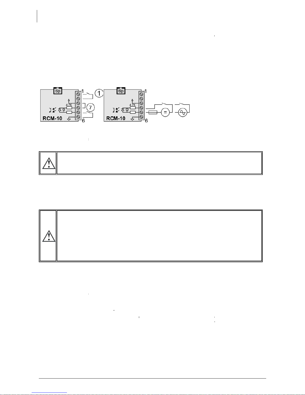
nnectin
e
comman
d
h
e operati
o
and 2. W
h
e
rminals 4 t
6
. It can be
b
y a voltag
e
W
ERIN
G
i
s imperati
v
rewed tigh
t
e
interior of
up of the
X
t
in the rev
e
cting the b
too high
o
x
ample, inst
a
the Xtend
e
o
larity of th
e
e
lt and will
the conn
e
e
nder pro
v
o
larity, it will
g
the Xtend
e
e
r is suppli
e
battery is
ion {1111}
a
cting the c
o
h
e output
p
AC out” (4
6
t
ing the inp
o
urce (gen
device a
u
s
at the out
p
lation is n
o
s
recomme
n
o
te control.
g the re
m
d
module
R
o
n of the sy
h
en this co
n
o 6 of mod
u
controlled
e
AC or DC
.
G
UP TH
E
v
e that the
t
before th
the conne
c
X
tender m
u
e
rse order.
attery
o
r inappro
p
a
lling a 24
V
e
r has bee
e
battery) it
have to b
e
e
ctions to t
h
v
es not to
w
have to b
e
e
r(s) in ope
r
e
d and is re
a
powered
u
a
ctivated.
o
nsumers a
p
rotection
d
6
) lights up
o
ut circuit b
r
erator or e
l
u
tomaticall
y
p
ut are the
r
o
w in oper
a
n
ded to c
a
Please ref
e
m
ote co
m
R
CM10 can
stem. A co
n
n
tact and
c
u
le RCM-10
by a dry
c
.
of max 60
E
INSTA
L
closing ca
p
e installati
o
c
tion com
p
u
st be carri
e
p
riate batt
e
V
battery in
n connect
is highly lik
e
e
replaced.
h
e Xtender
w
ork corre
c
e
returned t
o
r
ation using
a
dy for op
e
u
p, the m
a
t the outpu
d
evice (F) if
o
r flashes (i
n
r
eaker(s) (H
)
l
ectrical gri
d
y
goes int
o
r
efore supp
a
tion. If pa
r
a
rry this out
i
e
r to the op
e
V.3.1.0
m
mand
m
be “hot pl
u
n
tact free
o
c
losed, the
are used
a
c
ontact (7)
V eff. acro
s
L
LATIO
N
p
for the c
o
o
n is energi
s
p
artment.
e
d out in th
e
e
ry voltage
the Xtend
e
ed the wr
o
e
ly that the
If such is t
h
including t
h
c
tly after r
e
o
your distri
the main
O
e
ration. If y
o
a
in switch
t
existing, a
n
n
the event
)
d
) valid in
f
o
transfer
a
lied directl
y
r
ticular co
n
i
mmediatel
e
rating inst
r
m
odule R
u
gged” on
o
f potential
apparatus
a
s comman
d
between
5
s
s pin 4 an
d
N
o
nnection
c
s
ed. There
e
order giv
e
may serio
u
e
r 3000-12.
o
ng way
a
protection
h
e case, it
w
h
e battery.
e
connectin
g
butor for re
p
O
N/OFF swit
o
u require i
(1) must b
e
n
d/or press
of an abs
e
f
requency
a
a
nd will st
a
y
by the po
w
n
figuration
o
y. Adjustm
e
r
uctions for
CM10 (X
T
connector
(1) can b
e
is stopped
d
entry as
d
5
and 6 wit
h
d
5
c
ompartm
e
are dange
e
n below.
A
u
sly dama
g
a
round by
fuse on th
e
w
ill be nec
e
If, after re
p
g
the batt
e
p
air.
ch (1)
mmediate
e
in the “
O
the ON/OF
e
nce of con
a
nd voltag
e
a
rt to cha
r
w
er source
o
r adjustm
e
e
nts must b
e
this access
o
U
T
M only)
“RCM-10”
(
e
connecte
as describ
e
d
escribed i
n
h
a bridge
e
nt be inst
a
rous volta
g
A
ny Power
o
g
e the Xte
n
accident (
e
battery c
a
e
ssary to di
s
p
lacing the
e
ry with th
e
start-up of
t
O
N” positi
o
F button (4
sumers).
e is presen
t
r
ge the b
a
present at
t
e
nt is requ
i
e
made wi
t
o
ry.
U
ser manua
l
(
15) withou
t
d betwee
n
e
d in Chap
.
n
the chap
.
between
3
a
lled and
g
es within
o
ff must b
e
n
der. For
incorrect
a
ble may
s
connect
fuse, the
e
correct
t
he inverte
r
o
n and th
e
1). The ligh
t
t
at the A
C
tteries. Th
e
t
he input.
i
red by th
e
t
h the RCC
-
l
t
n
.
.
3
e
r
e
t
C
e
e
-
This manual suits for next models
21
Table of contents
Other Studer Power Supply manuals


