FEAS LDR30MH24 User manual

1. Funktionsweise
Das LDR30MH24 ist ein 24V-Schaltnetzteil mit
integriertem Akkumulator um die Versorgung eines
Verbrauchers bei Netzausfall aufrecht zu erhalten.
1. Mode of operation
The LDR30MH24 is a 24V power supply with integrated
battery which buffers the output in case of line in failure.
2. Installation
The LDR30MH24 is suggested to be mounted on a DIN-
rail.
CAUTION! For improved heat dissipation, the device
should have a minimum separation distance of 15 mm
from other devices.
2. Montage
Das LDR30MH24 ist für die Hutschienenmontage
vorgesehen.
ACHTUNG! Zur besseren Wärmeabfuhr sollte das Gerät
einen Mindestabstand zu anderen Geräten von 15mm
haben.
3. Elektrischer Anschluss
Das Gerät laut Anschluss-Schema unten rechts an-
schließen. Hierbei unbedingt die allgemeinen Sicher-
heitsvorschriften auf der Rückseite beachten.
Unsachgemäßer Anschluss kann zu einem Defekt des
Gerätes führen.
3. Electrical connection
Take care of a correct electrical connection. Take the
wiring diagram at the bottom of this side as help.
Inappropriate connection can lead to a defect of the
device.
4. Fernüberwachung
Um eine Fernüberwachung des LDR30MH24 zu
ermöglichen, sind vier Relais integriert. Die Funktion der
Relais kann dem Anschluss-Schema unten rechts
entnommen werden.
Manuelle Abschaltung im Pufferbetrieb
“Schlafenlegen”
Wenn sich das LDR30MH24 im Pufferbetrieb befindet,
d.h. es liegt keine Netzspannung an, kann das Gerät
über das anlegen einer Gleichspannung von 18 bis 50V
an Klemme 6 und 7 deaktiviert werden. In diesem
Zustand wird die Stromentnahme aus dem Akkumulator
auf ein Minimum reduziert.
4. Remote monitoring
In order to enable a remote monitoring of the
LDR30MH24 four relays are built in and routed to the
terminals. Look at the wiring diagram for exact
information.
.
Manual shut down in buffering mode
“sleep mode”
During the buffer mode it’s possible to shut down the
LDR30MH24 manually. To shut down the device a
voltage of 18V - 50V DC has to be applied to connector 6
and 7. In that case the LDR30MH24 switches off and cut
off the battery from the line. Therefore the battery
discharge is reduced to a minimum.
LED-Anzeigen / LED-Display
Netzeingang OK
Line in ok
Normalzustand / Normal mode
Akkumulator geladen
Battery charged
aufblinkend: Batterie lädt
Flashing up: battery charging
Akkumulator wird getestet
Testing Battery
Akkumulator OK
Battery ok
Netzeingang fehlt
Line in failure
Warnzustand / Alert mode
abblinkend: Batterie entlädt
Flashing down: battery discharging
Akkumulator defekt / getrennt
Battery defect / disconnected
Netz / Line
Akku - Laden
Charging - Battery
Akku Alarm / Accu Alarm
Überlast / Overload
Übertemp. / Overtemp.
Pufferbetrieb / Buffer mode
Netzteil OK
Power supply ok Netzteil unter Überlast
Power supply under overload
Temperatur OK
Temperature ok
Temperatur zu hoch
Temperature too high
Netzteil arbeitet
Power supply active
Versorgung aus Akkumulator
Supply from battery
red
orange
red
red
red
orange
green
green
orange
orange
off
off
off
off
Betriebsanleitung
Bitte sorgfältig beachten!
Operating instructions
Read attentive please!
LDR30MH24
Anschluss-Schema / Wiring diagramm
1 - Gemeinsamer Relais-Kontakt / Shared relay contact
Gemeinsamer Anschluss aller Relais.
Shared contact for all relays.
2 - Übertemperatur / Overtemperature
Öffnet wenn die Temperatur im LDR30MH24 zu hoch ist.
Opens when the temperature in the LDR30MH24 is too
high.
3 - Akkumulator defekt / Battery defect
Öffnet wenn der Akkumulator nicht angeschlossen oder
defekt ist.
Opens when the battery isn´t connected or defect.
4 - Akkumulator entladen / Battery discharged
Öffnet wenn der Akkumulator während eines Netzausfalls
fast völlig entladen ist. // Opens when line in is lost and
the battery is nearly discharged.
5 - Netzausfall / Line in lost
Öffnet wenn die Versorgungsspannung ausfällt.
Opens when the supply is lost.
6 + 7 - Schlafenlegen / Sleep mode
An 6 und 7 eine Gleichspannung von 18V bis 50V anlegen
um das “Schlafenlegen” zu aktivieren.
Apply 18V till 50V direct current at 6 and 7 to activate the
sleep mode.
L1
85 - 270 VAC
oder / or
120 - 380 VDC
PE
N
14
236
57
+
-
Ausgang / Output
24V / 2,0 A
DC
gepuffert / buffered
intern
internal
Ausgangsspannung- und Pufferzeit-Einstellung / Output voltage and buffer time adjustment
Einstellung Pufferzeit
Adjustment buffer time
Einstellung Ausgangsspannung
Adjustment output voltage
Begrenzung der Pufferzeit von 1 bis 20 Minuten
und unbegrenzt (25. Umdrehung nach rechts)
Limiting of buffer time from 1 till 20 minutes and unlimited (25th turn right)
Einstellung der Ausgangsspannung von 22,5 V bis 29,5V
Adjustment of the output voltage from 22,5V till 29,5V
Befestigung Alternativen
Mounting alternatives
Hutschiene
rail
Geeignet für M6
Schrauben
Suitable for
M6 screws
6,1 mm
Mutter M3
Nut M3
Schraube M3x6
Screw M3x6
Mutter M3
Nut M3
Schraube M3
Screw M3
a) b) c)
Betriebsanleitung
Bitte sorgfältig beachten!
Operating instructions
Read attentive please!
LDR30MH24
!
Zum erreichen der maximalen Ladekapazität ist es zwingend
erforderlich:
1)Bei der ersten Inbetriebnahme des Ladereglers die Akkus
mindestens 24 Stunden zu laden.
2)Die Akkus durch mindestens 3 volle Lade- und
Entladezyklen bei gleichzeitiger Stromentnahme (ca 50%)
zu konditionieren.
Wenn die oben beschriebene Prozedur nicht durchgeführt
wird, kann es vorkommen, dass schon nach wenigen
Minuten die LED “Akku voll” leuchtet, obwohl der Akku noch
nicht vollständig geladen ist.
For reaching the optimal capacity it is strongly essential:
1)With the first beginning of operation to charge the accus
for min. 24 hours.
2)To charge and discharge the accus minimum three times,
in order to condition the accus. This procedure should be
made with ca. 50% output load.
If the procedure mentioned above are not enforced, it is
possible that the LED “Akku voll” is switching on even if the
accu is not fully charged.
- konform GmbH
Postfach 1521
D - 22905 AHRENSBURG
Telefon: 04102 - 42082
Telefax: 04102 - 40930
www.feas.de
©2017 ®Stand: 16.08.2017
Induktive Verbraucher (Schütze, Motoren,
Magnetventile, etc.) die nicht ordnungsgemäß
nach den relevanten Richtlinien entstört sind
(Varistoren, RC-Glieder, etc.), können zur Störung
des Netzteiles und der Laderegelung führen.
!
Um den Schutz des integrierten Schaltnetzteiles
vor Überspannung im Eingangskreis zu
gewährleisten, ist eine Vorsicherung vorzusehen
(bei 230V - 2,0A träge).
AC
!
Inductive consumers (contactors, motors,
magnetic valves etc.) which have not been
correctly interference-suppressed in accordance
to the relevant guidelines (varistors, RC
elements, etc.) may cause the power supply and
charging regulation to malfunction.
!To protect the input of the integrated power
supply against overvoltage the input has to be
fused (at 400V - 2,0A delayed each phase).
AC
!
Output data
Control data
Operation data
Safety devices
Savety data
Applied construction regulations
Input data
Mechanics
Technical data
Input voltage AC 85 - 270 VAC (0-400 Hz)
Input voltage DC 120 - 380 VDC
Input current at nominal load at 230 VAC max. 0,25 A
Peak input current
Protective circuit
< 5,0 A at 270 VAC
Transient voltage suppressor varistor
Output voltage Unom
Output current Inom
Battery type
Residual ripple (20MHz)
24VDC ( 22,5V till 29,5V adjustable )
ca. 1,6 x Inom
NiMh 24V 0,72 Ah
< 50 mVPP
Control deviation load
Control deviation line
Control response time
< 200 mV with load variation 10.....90%
< 10 mV with line variation ±10%
< 10 ms with load variation 10.....90%
Duty cycle
Operation temperature range
Thermal derating
Storage temperature range
100%
-20°C up to +70°C (battery charge -5°C up to 45°C)
from 50°C with 3% per degree celsius
-30°C up to +85°C (without battery)
Cooling selfcooling, recommended space 15mm each side
Input fuse
Output fuse
Overload protection
MTBF
at 230VAC 2,0 A delayed
not necessary, short circuit proof
integrated
>380.000 h without battery
Test voltage transformer
High voltage resistance
5 kVAC in accordance to VDE 0551
Prim. to Sec. 3,75 kVAC acc. to VDE 0806 / IEC 380
EMI suppression
Protection class
according to VDE 0871B, EN 55022/B
class 1, with PE connection (EN 60950)
Extra low safety potential
Ambient humidity
PELV (EN60204), SELV (EN 60950)
95% relative humidity, yearly avarage
bedewing possible, allowed for use in tropical ambient
IP 65
IP 20 (BGV A3)
>30g at 33Hz in X,Y and Z, acc. to IEC 60068-2-27
without Battery
Protective class enclosure
Protective class terminals
Vibration proof
VDE VDE 0100,0110,0113,0140-1,0551,0160/W2,0806
IEC IEC 60950,IEC61000-6-1-2-3-4,IEC60068-2-3,
IEC 60068-2-11-52,IEC 60529,IEC 380
EN EN60950,EN61140,EN61000-6-1,EN61000-6-2,
EN61000-6-3,EN61000-6-4,EN55022, EN55011,
EN61000-3-2,EN61000-3-3,EN50204, EN60204,
EN60529,EN61000-4-2-3-4-5-6-8-11, EN60068-1,
CSA / UL CSA-C 22.2 / UL60950, UL508, UL1950
Mounting DIN-rail mounting
Dimensions W x H x D 108mm x 100mm x 120mm
Weight approx. 2,3 kg
Relay contact rating 5A / 30VDC - 5A / 250VAC
Battery monitoring, charge controller Microprocessor controlled
2A ( 3A boost )
Current limiting
Ausgangsgrößen
Regelgrößen
Betriebsdaten
Schutzeinrichtungen
Sicherheitsdaten
Angewandte Bauvorschriften
Eingangsgrößen
Mechanik
Technische Daten
Eingangswechselspannung 85 - 270 VAC (0-400 Hz)
Eingangsgleichspannung 120 - 380 VDC
Stromaufnahme je Phase bei bei 230 VAC max. 0,25 A
Einschaltstromstoß
Schutzbeschaltung
< 5,0 A bei 270 VAC
Transientenüberspannungsschutz Varistor
Ausgangsspannung Unenn
Ausgangsstrom Inenn
Akkumulatortyp
Restwelligkeit (20MHz)
24VDC ( von 22,5V bis 29,5V einstellbar )
2A ( 3A Boost )
NiMh 24V 0,72 Ah
< 50 mVSS
Regelabweichung Last
Regelabweichung Netz
Regelzeit
< 200 mV bei Laständerung 10.....90%
< 10 mV bei Netzspannungsänderung ±10%
< 10 ms bei Laständerung 10.....90%
Einschaltdauer (ED)
Arbeitstemperatur
Leistungsabweichung bei
Lagertemperaturbereich
100%
-20°C bis +70°C (Akku-Ladung -5°C bis 45°C)
ab 50°C mit 3% pro Grad Celsius
-30°C bis +85°C (ohne Akkumulator)
Kühlung natürliche Konvektion, empf. Freiraum je 15mm
Vorsicherung
Ausgangssicherung
Überlastschutz
MTBF
bei 230VAC 2,0 A träge
nicht erforderlich da kurzschlussfest
im Gerät integriert
>380.000 h ohne Akkumulator
Prüfspannung Transformator
Hochspannungsfestigkeit
5 kVAC gemäßt VDE 0551
Ein.- /Ausgang 3,75 kVAC nach VDE0806 / IEC380
Funkentstörgrad
Schutzklasse
gemäß VDE 0871B, EN 55022/B
Klasse 1, mit PE-Anschluss (EN 60950)
Schutzkleinspannung
Umgebungsfeuchte
PELV (EN60204), SELV (EN 60950)
95% relative Feuchte im Jahresdurchschnitt
Betauung möglich - tropentauglich
IP 65
IP 20 (BGV A3)
>30g bei 33Hz in X,Y und Z, nach IEC 60068-2-27
ohne Akkumulator
Schutzart Gehäuse
Schutzart Klemmen
Rüttelfestigkeit
VDE VDE 0100,0110,0113,0140-1,0551,0160/W2,0806
IEC IEC 60950,IEC61000-6-1-2-3-4,IEC60068-2-3,
IEC 60068-2-11-52,IEC 60529,IEC 380
EN EN60950,EN61140,EN61000-6-1,EN61000-6-2,
EN61000-6-3,EN61000-6-4,EN55022, EN55011,
EN61000-3-2,EN61000-3-3,EN50204, EN60204,
EN60529,EN61000-4-2-3-4-5-6-8-11, EN60068-1,
CSA / UL CSA-C 22.2 / UL60950, UL508, UL1950
Befestigung Hutschienenmontage
Abmessungen B x H x T 108mm x 100mm x 120mm
Gewicht ca. 2,3 kg
Relais-Kontaktbelastbarkeit 5A / 30VDC - 5A / 250VAC
Akkumulatorüberwachung, Mikroprozessor gesteuert
ca. 1,6 x InennStrombegrenzung
Betriebsanleitung
Bitte sorgfältig beachten!
Operating instructions
Read attentive please!
LDR30MH24 Betriebsanleitung
Bitte sorgfältig beachten!
Operating instructions
Read attentive please!
LDR30MH24
7. Allgemeine Sicherheitsvorschriften
Beim Umgang mit Produkten, die mit elektrischen Spannungen in
Berührung kommen, müssen die gültigen VDE / IEC / EN Vorschriften
beachtet werden. Besonders sei auf folgende Vorschriften hingewiesen:
VDE 0100, VDE 0550 / 0551, VDE 0711, VDE 0860, IEC 664, IEC 742,
IEC 570, IEC 65
Bei Nichtbeachtung der Bedienungsanleitung oder der
Anschlußvorschrift, z.B. bei Vertauschen der Anschlußklemmen, kann
das Gerät oder die Anlage beschädigt werden und der Betreiber verliert
seinen möglichen Haftungsanspruch.
Werkzeuge dürfen an Geräten, Bauteilen oder Baugruppen nur benutzt
werden, wenn sichergestellt ist, dass die Geräte von der
Versorgungsspannung getrennt sind und interne elektrische Bauteile
entladen sind.
Vor dem Öffnen des Gerätes den Netzstecker ziehen und sicherstellen,
dass das Gerät spannungslos ist und bleibt. Bauteile, Baugruppen oder
Geräte dürfen nur in Betrieb genommen werden, wenn sie vorher in ein
berührungssicheres Gehäuse eingebaut wurden. Während des Einbaus
müssen sie stromlos sein.
Spannungsführende Kabel oder Leitungen mit denen das Gerät, das
Bauteil oder die Baugruppe verbunden sind müssen stets auf
Isolationsfehler oder Bruchstellen untersucht werden. Bei Feststellen
eines Fehlers in der Zuleitung muß das Gerät unverzüglich aus dem
Verkehr genommen werden, bis die defekte Leitungen ausgewechselt
worden sind.
Der Anwender hat dafür Sorge zu tragen, dass die angegebenen
Gerätedaten nicht überschritten werden.
Wenn aus den vorgelegten Beschreibungen für den Anwender oder
Erwerber nicht eindeutig hervorgeht, welche Kennwerte für ein Gerät
oder Bauteil gelten, so muss stets ein Fachmann um Auskunft ersucht
werden.
7.General safety rules
When working with products which are in contact to dangerous electrical
voltages, attention must be payed to the relevant valid VDE / IEC / EN
regulations. Especialy with refrence to the following rules:
VDE 0100, VDE 0550 / 0551, VDE 0711, VDE 0860, IEC 664, IEC 742,
IEC 570, IEC 65
In case of non-observance of this instructions the unit or other equipment
might be damaged and no warranty or liability could be accepted.
When it is necessary to use tools on the units components parts or
subassemblies make sure that the power is disconnected from the units
and all capacities are discharged.
Before opening the equipment disconnect the power cord and make sure
that the contacts dont got any voltage left. It is only allowed to set
components parts, subassemblies or units into operation if they are
mounted in an insulated housing. During the installation all units have to
be disconnected from power sources.
Power cords and leads which are connected to the units, components or
subassemblies have to be inspected for damaged insulation. If a failure is
detected the unit or the subassembly has to be put out of service at once.
It is not allowed to reopen the unit or the subassembly before replacing
the damaged power cord.
It is up to the user’s responsibility that the specification limits of the
device are not exeeded.
If the user isnt fully able to relate the technical guidelines, a technical
adviser has to be asked for information.
The observance of construction requirements and safety rules (VDE,
IEC, employers liability insurenance i.e.) is subject to the user/customer.
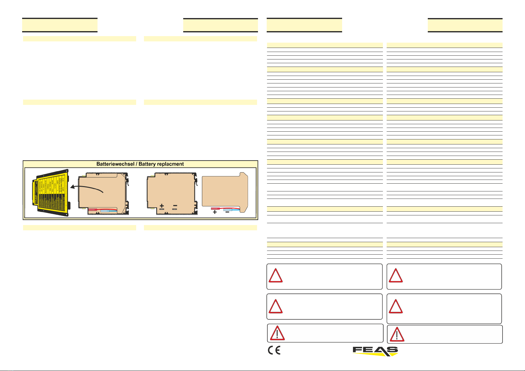
6. Batteriewechsel
Schritt 1: Eingangsspannung ausschalten.
Schritt 2: Gerät auf die linke Seite legen.
Schritt 3: Die 4 Innensechskantschrauben (M3) von der
Seitenplatte abschrauben.
Schritt 4: Akkumulatoren herausnehmen und die Kabel von
den Steckern trennen.
Schritt 5: Neue Akkumulatoren an die Stecker anschließen
Schritt 6: Akkumulatoren in den Batterieraum schieben.
Schritt 7: Seitenplatte wieder aufschrauben.
Schritt 8: Die alten Akkus ordnungsgemäß und
umweltgerecht entsorgen!
5. Temperaturüberwachung
Um den integrierten Akkumulator vor unzulässiger
Erwärmung zu schützen, ist das LDR30MH24 mit einem
thermischen Ladeschutz ausgerüstet.
Dieser Ladeschutz bewirkt, das für den oben genannten
Fall, die Akkumulatoren nicht mehr geladen bzw.
nachgeladen werden und somit kein voller Pufferbetrieb
gewährleistet ist. Erreicht die Erwärmung ein für das
Netzteil kritisches Level, erfolgt eine Leistungsreduktion
um das Gerät vor Überhitzung zu schützen.
Aus diesen Gründen bitte für ausreichende Kühlung
sorgen!
5.Temperature monitor
In order to protect the built-in batteries against
inadmissible heating the LDR30MH24 is equipped with a
thermal charge protection.
This charge protection has the effect that for the
above mentioned case the batteries won’t be charged or
recharged anymore. Therefore the buffering is limited.
If the heating reaches critical limits a powerreduction is
performed to protect the devices against overheating.
For this reason please provide for sufficient
cooling!
6.Battery replacment
Step 1: Switch off input voltage.
Step 2: Turn the device on the left side.
Step 3: Loose the 4 screws (M3) from the side plate.
Step 4: Remove storage batteries and disconnect the cables.
Step 5: Connect new storage batteries.
Step 6: Slide storage batteries into the battery compartment.
Step 7: Screw on base plate again.
Step 8: Dispose the old storage batteries properly and
environmentally safely!
Für den ordnungsgemäßen Betrieb des Gerätes ist ein
Überspannungsschutz nach VDE0185-4 / EN62305-4,
eine Vorsicherung, gemäß Tabelle, und optional ein
Netzfilter vorzusehen.
For proper operation of the device provide an
overvoltage protection, according VDE0185-4 /
EN62305-4, an input fuse as shown in table and
optionally a line filter.
- konform GmbH
Postfach 1521
D - 22905 AHRENSBURG
Telefon: 04102 - 42082
Telefax: 04102 - 40930
www.feas.de
©2017 ®Stand: 16.08.2017
Other FEAS Power Supply manuals


