Studer A1 Training manual

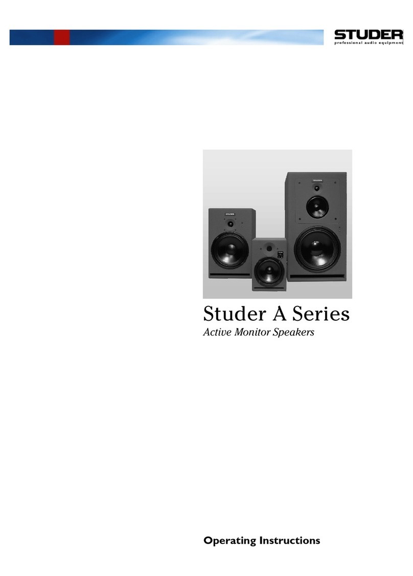
Studer A Series
Active Monitor Speakers
Operating and
Service Instructions


A Series Active Monitor Speakers
Date printed: 29.02.00 Contents E0/1
CONTENTS
1Welcome!...................................................................................................................................E1/1
1.1 Basics .............................................................................................................................................................E1/1
1.2 Safety and Connections..................................................................................................................................E1/3
1.2.1 Utilization for the Purpose Intended.........................................................................................................E1/3
1.2.2 Unpacking and Inspection........................................................................................................................E1/3
1.2.3 Installation...............................................................................................................................................E1/3
2General......................................................................................................................................E2/1
2.1 Scope of Delivery ...........................................................................................................................................E2/1
2.2 Options...........................................................................................................................................................E2/1
2.3 Block Diagrams .............................................................................................................................................E2/2
2.4 Technical Specifications................................................................................................................................E2/3
3Operation ..................................................................................................................................E3/1
3.1 Connectors, Controls.....................................................................................................................................E3/1
4Service Instructions...................................................................................................................E4/1
4.1 General ..........................................................................................................................................................E4/1
4.2 Spare Parts.....................................................................................................................................................E4/1
4.3 A1 Service......................................................................................................................................................E4/2
4.3.1 A1: Settings on the PCB ..........................................................................................................................E4/3
4.3.1.1 A1: Required Test Tools.....................................................................................................................E4/3
4.3.1.2 A1: Initial Settings..............................................................................................................................E4/3
4.3.1.3 A1: Powering Up ................................................................................................................................E4/3
4.3.1.4 A1: Supply Voltages...........................................................................................................................E4/3
4.3.1.5 A1: Input Gain Check and EQ Preadjustments....................................................................................E4/4
4.3.1.6 A1: Input Common Mode Rejection Ratio (CMMR) ...........................................................................E4/5
4.3.1.7 A1: Quiescent Current Setting............................................................................................................E4/5
4.3.1.8 A1: Woofer Amplifier Output.............................................................................................................E4/6
4.3.1.9 A1: Tweeter Amplifier Output............................................................................................................E4/7
4.3.1.10 A1: Limiter Threshold........................................................................................................................E4/8
4.3.2 A1: Checks on the assembled Unit...........................................................................................................E4/9
4.3.2.1 A1: Required Test Tools.....................................................................................................................E4/9
4.3.2.2 A1: Initial Settings..............................................................................................................................E4/9
4.3.2.3 A1: Insulation Check..........................................................................................................................E4/9
4.3.2.4 A1: Measurement Setup in the Anechoic Room ................................................................................E4/10
4.3.2.5 A1: SPL and EQ Fine-Adjustment....................................................................................................E4/11
4.3.2.6 A1: Distortion Check........................................................................................................................E4/11
4.3.2.7 A1: Polarity Check ...........................................................................................................................E4/12
4.3.2.8 A1: Overall Phase Check .................................................................................................................E4/12

A Series Active Monitor Speakers
E0/2Contents Date printed: 29.02.00
4.4 A3 Service....................................................................................................................................................E4/13
4.4.1 A3: Settings on the PCB ........................................................................................................................E4/14
4.4.1.1 A3: Required Test Tools...................................................................................................................E4/14
4.4.1.2 A3: Initial Settings ...........................................................................................................................E4/14
4.4.1.3 A3: Powering Up..............................................................................................................................E4/14
4.4.1.4 A3: Supply Voltages.........................................................................................................................E4/14
4.4.1.5 A3: Input Gain Check and EQ Preadjustments..................................................................................E4/15
4.4.1.6 A3: Input Common Mode Rejection Ratio (CMMR) .........................................................................E4/16
4.4.1.7 A3: Quiescent Current Setting..........................................................................................................E4/16
4.4.1.8 A3: Woofer Amplifier Output...........................................................................................................E4/17
4.4.1.9 A3: Tweeter Amplifier Output..........................................................................................................E4/18
4.4.1.10 A3: Limiter Threshold......................................................................................................................E4/19
4.4.1.11 A3: Overheat Protection Check.........................................................................................................E4/19
4.4.2 A3: Checks on the assembled Unit.........................................................................................................E4/20
4.4.2.1 A3: Required Test Tools...................................................................................................................E4/20
4.4.2.2 A3: Initial Settings ...........................................................................................................................E4/20
4.4.2.3 A3: Insulation Check........................................................................................................................E4/20
4.4.2.4 A3: Measurement Setup in the Anechoic Room ................................................................................E4/21
4.4.2.5 A3: SPL and EQ Fine-Adjustment....................................................................................................E4/22
4.4.2.6 A3: Distortion Check........................................................................................................................E4/22
4.4.2.7 A3: Polarity Check ..........................................................................................................................E4/23
4.4.2.8 A3: Overall Phase Check..................................................................................................................E4/23
4.5 A5 Service....................................................................................................................................................E4/24
4.5.1 A5: Settings on the PCB ........................................................................................................................E4/25
4.5.1.1 A5: Required Test Tools...................................................................................................................E4/25
4.5.1.2 A5: Initial Settings ...........................................................................................................................E4/25
4.5.1.3 A5: Powering Up..............................................................................................................................E4/25
4.5.1.4 A5: Supply Voltages.........................................................................................................................E4/25
4.5.1.5 A5: Input Gain Check and EQ Preadjustments..................................................................................E4/26
4.5.1.6 A5: Input Common Mode Rejection Ratio (CMMR) .........................................................................E4/27
4.5.1.7 A5: Quiescent Current Setting..........................................................................................................E4/28
4.5.1.8 A5: Woofer Amplifier Output...........................................................................................................E4/28
4.5.1.9 A5: Mid-range Amplifier Output......................................................................................................E4/29
4.5.1.10 A5: Tweeter Amplifier Output..........................................................................................................E4/30
4.5.1.11 A5: Limiter Threshold......................................................................................................................E4/31
4.5.1.12 A5: Overheat Protection Check.........................................................................................................E4/31
4.5.2 A5: Checks on the assembled Unit.........................................................................................................E4/32
4.5.2.1 A5: Required Test Tools...................................................................................................................E4/32
4.5.2.2 A5: Initial Settings ...........................................................................................................................E4/32
4.5.2.3 A5: Insulation Check........................................................................................................................E4/32
4.5.2.4 A5: Measurement Setup in the Anechoic Room ................................................................................E4/33
4.5.2.5 A5: SPL and EQ Fine-Adjustment....................................................................................................E4/34
4.5.2.6 A5: Distortion Check........................................................................................................................E4/34
4.5.2.7 A5: Polarity Check ..........................................................................................................................E4/35
4.5.2.8 A5: Overall Phase Check..................................................................................................................E4/35
4.6 Appendix: Frequency Response Measurements .........................................................................................E4/36
4.6.1 General..................................................................................................................................................E4/36
4.6.2 Standing Waves, Reflections, and Smoothing.........................................................................................E4/36
4.6.3 MLS Technology for Frequency Response Measurements ......................................................................E4/37
4.6.4 Quasi-Anechoic Measurements and Low-Frequency Limitations............................................................E4/38
4.6.5 MLS Advantages ...................................................................................................................................E4/39
5Diagrams......................................................................................................................................E5

A Series Active Monitor Speakers
Date printed: 29.02.00 Welcome! E1/1
1WELCOME!
We are happy to welcome you in the circle of the users of Studer's A series
active speakers, and we felicitate you on your selection. Thanks to Studer's
experience collected during more than 40 years of business in the profes-
sional audio products field, you may expect that the performance of your
new unit will fulfill your highest demands.
1.1 Basics
With the A series, Studer has created a family of active speaker systems.
With exterior dimensions kept at a minimum, but nevertheless with high
sound pressure levels, these speakers are suited for many different applica-
tions. For audition rooms and continuity cubicles, for the editing studio and
control rooms, for use in mobile applications or OB vans, the A series offers
ideal problem-oriented solutions.
The Studer A series active speakers can be adjusted to any individual re-
quirement by means of various controls. Differences in operating levels or
differences due to speaker placement can be compensated thanks to the vari-
able input sensitivity and the bass roll-off controls. For horizontal place-
ment, the A5's mid-range/tweeter unit can be rotated by ±90° after loosening
four screws.
To meet professional standards, the A series is equipped with an XLR-
compatible connector and electronically balanced line input (A1) or trans-
former-balanced line input (A3 and A5).
The most important characteristics of the A series active speakers can be
summarized as follows:
•Active 2- or 3-way speakers for high sound pressure levels in near-field
applications or medium- and large-sized monitoring rooms.
•Suited for all commonly used operating levels, input sensitivity continuously
adjustable.
•Low distortion rating; the magnetic flux is stabilized by damping the coil
reaction.
•Exceptional damping of the individual systems by negative output imped-
ance of the power amplifiers.
•Matched signal propagation delay between the individual transducers
through separate electronic delay lines.
•Group delay compensated band-pass filters.
Negative output impedance: A speaker diaphragm should accurately follow the electrical excitation. In
the Studer A series active speakers, this is achieved with negative output
impedance in all power amplifiers, which efficiently attenuates undesired
echo oscillations of the diaphragm. Each of the frequency ranges features
its own power amplifier with negative output impedance. This forces the
diaphragm to exactly follow the input signal, and undesired responses (dia-
phragm and enclosure echoes) are suppressed. Percussive signals in par-
ticular (e.g. applause) are reproduced very accurately.
This principle is also an essential prerequisite for other improvements:
•Utilization of optimum crossover network techniques
•Other distortion reduction measures.

A Series Active Monitor Speakers
E1/2Welcome! Date printed: 29.02.00
Helmholtz resonator A cavity with an external opening is referred to as Helmoltz resonator. If a
driven diaphragm is added to this system, the well-known “bass reflex” en-
closure is obtained, having the advantage of significantly more energy gain
in the bass reflex resonance area. The transmission range can thus be ex-
panded toward the low end without overloading the speaker.
In combination with the negative output impedance, it is possible to consider
this arrangement strictly as a Helmholtz resonator again, being easily com-
pensated for the bass reflex drawbacks by electronic means. Such a combi-
nation achieves clean bass reproduction down to frequencies amazingly low
for the given enclosure size.
Group-delay-compensated filters The evaluation of a speaker cannot simply be based on one single point of
the room, but the entire radiation behavior must be considered.
The division of the frequency spectrum, unfortunately made necessary by
various reasons such as Doppler effect, partial oscillations of the dia-
phragms, etc., creates additional problems.
If the individual speaker systems are arranged vertically, the horizontal ra-
diation characteristic depends almost exclusively on the quality of the chas-
sis. In the vertical direction, however, a bundled aggregate signal is ob-
tained. If the partial signals are not in phase with each other – either due to
different acoustic propagation times or phase rotation in the crossover – the
radiation lobe changes its direction in the transition zones. If the ear is not
accurately positioned, dips or even peaks in the frequency response can
strongly influence the sound impression and the localization of the sound
source.
Delay compensation The distance from the point of origin of the sound to the speaker surface
varies because the individual speaker systems have different mounting
depth. With wide-band signals, this normally leads to dispersion (i.e. the in-
dividual frequency components arrive at the listening position at different
times).
In the Studer A series active speakers, these differences in the transit time of
the audio signals are compensated by analog delay circuits maintaining the
necessary delay up to frequencies above the audio range.
Time delay compensation, negative output impedance of the power amplifi-
ers, and a sophisticated crossover design offering steep filter characteristics
and phase linearity, all together leads to the excellent impulse behavior of
the A series and to their greatly improved reproduction of transient music
signals.
Ideally suited for surround sound A unique feature of the A-Series studio monitors is that different speaker
types can be mixed for setting up a surround system. The simple reason for
this is the group-delay compensation.
Usually, combining different speaker types with uncompensated group-delay
can cause quite unpleasant phase-domain effects, resulting in sound sources
being placed in wrong positions. Parts of a signal panned to the right side
could then be localized behind the listener or in other undesired positions.
The different A-Series studio monitors feature identical phase response over
the whole frequency spectrum and therefore give an accurate sound source
positioning.

A Series Active Monitor Speakers
Date printed: 29.02.00 Welcome! E1/3
1.2 Safety and Connections
1.2.1 Utilization for the Purpose Intended
The Studer A series active speakers are designed for professional use. It is
presumed that the units are operated only by trained personnel; servicing
must be performed by qualified experts.
The electrical connections may be connected only to the appropriate volt-
ages and signals specified in this manual. Please consult the Safety and
EMC sections at the very beginning of this manual.
1.2.2 Unpacking and Inspection
Your new unit is shipped in a special packing which protects it against me-
chanical shock during transit. Care should be exercised when unpacking so
that its surfaces do not get marred.
Verify that the content of the packing agrees with the items listed on the
enclosed shipping list. Check the condition of the equipment for signs of
shipping damage. If there should be any complaints please immediately no-
tify the forwarding agent and your nearest Studer distributor.
Please retain the packing material because it offers the best protection in
case your unit ever needs to be transported.
1.2.3 Installation
Before any connection: Check the line voltage selector setting before connecting the unit to the
mains. The voltage selector is located inside the fuse holder next to the
power inlet. The unit can be operated on mains voltages of 115 or 230 VAC,
50 to 60 Hz. Also check for correct value of the primary fuse:
A1 230 V: T 1.6 A L 250 V (5 × 20 mm)
115 V: T 3.15 A L 250 V (5 × 20 mm)
USA and Canada: 115 V: 3.2 A slow blow UL/CSA (5 × 20 mm)
A3 230 V: T 0.8 A L 250 V (5 × 20 mm)
115 V: T 1.6 A L 250 V (5 × 20 mm)
USA and Canada: 115 V: 1.6 A slow blow UL/CSA (5 × 20 mm)
A5 230 V: T 0.5 A L 250 V (5 × 20 mm)
115 V: T 1.0 A L 250 V (5 × 20 mm)
USA and Canada: 115 V: 1.0 A slow blow UL/CSA (5 × 20 mm)
Mains cable: Depending on your country, the A Series Active Monitor Speakers come
with an IEC mains cable or a female IEC 320/C13 mains cable socket. This
socket has to be connected to an appropriate mains cable by a trained tech-
nician with respect to your local regulations. Refer to the “Installation” sec-
tion at the beginning of this manual.

A Series Active Monitor Speakers
E1/4Welcome! Date printed: 29.02.00
Danger! Repair work may only be performed by a trained service technician. The
primary fuse must be replaced by a spare fuse of exactly the same type.
The unit must not be opened by the user because of the risk of a severe
electric shock hazard!
Humidity: Do not use the units near any source of moisture or in excessively humid
environments.
Ventilation: In order to guarantee adequate air circulation, the unit's rear side must
not be mounted closer than 6 cm from a wall.
Magnetic radiation: Do not mount the A5 and A3 units closer than 40 cm from a video or com-
puter monitor.
Thanks to low magnetic dispersion drivers and additional screening, the
A1 units can be operated also next to video or computer monitors, or
measuring instruments.
Mounting facilities: Four tapped M6 inserts are located on the bottom of the A5 and A3 units.
They can be used for mounting it on a base plate, a wall-mount kit or a
stand (refer to section 2.2, Options).
The A5 cannot be mounted with a ceiling mounting kit. When mounted on
a stand or wall-mount, please make sure that the tilting angle in either di-
rection does not exceed 30°!
The A1 is shipped with a threaded mounting bracket for easy installation on
a microphone stand.
Location: The A series has been aligned for free placement, i.e. not close to walls or in
edges. Ideal mounting distances are 1...2 m from walls and at least 60 cm
from the floor. If operation of the A5 or A3 units near room boundaries is
required, the resulting bass boost can be compensated with the ROLL OFF
control.
On the A1 unit the ROLL OFF control is not available, because this type
and size of loudspeaker usually is not operated near room boundaries.
Other manuals for A1
1
This manual suits for next models
2
Table of contents
Other Studer Speakers manuals
