.........................................................................................................
Outstanding Features
2
..............................................................................................................
Panel Description
3
Front Pimel
...........................................................
-.-.
3
...................................................
....................................................................................
Right Side Panel
:~rlcl
I.cft Side 1':mel
4
...................................................................................................................
Connections
5
..................................................
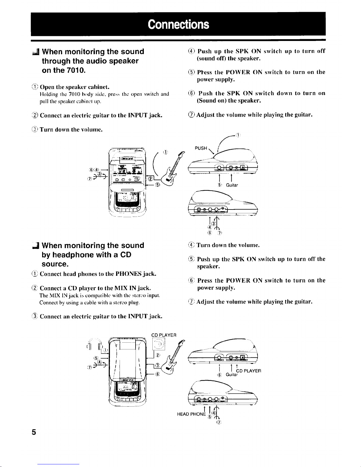
When monitoringthe so1111c1through the audio speaker on the 7010
5
.........................................................
When nionittrring the sound hy licadphone with
a
CD
source
5
..................................................................
\Vhcn monitoring the so1.1nc1Illrough guitiir amplifier
6
..............................................................................
Whcn
connecting
to cilssclIc tape recorder
6
.......................................................................................
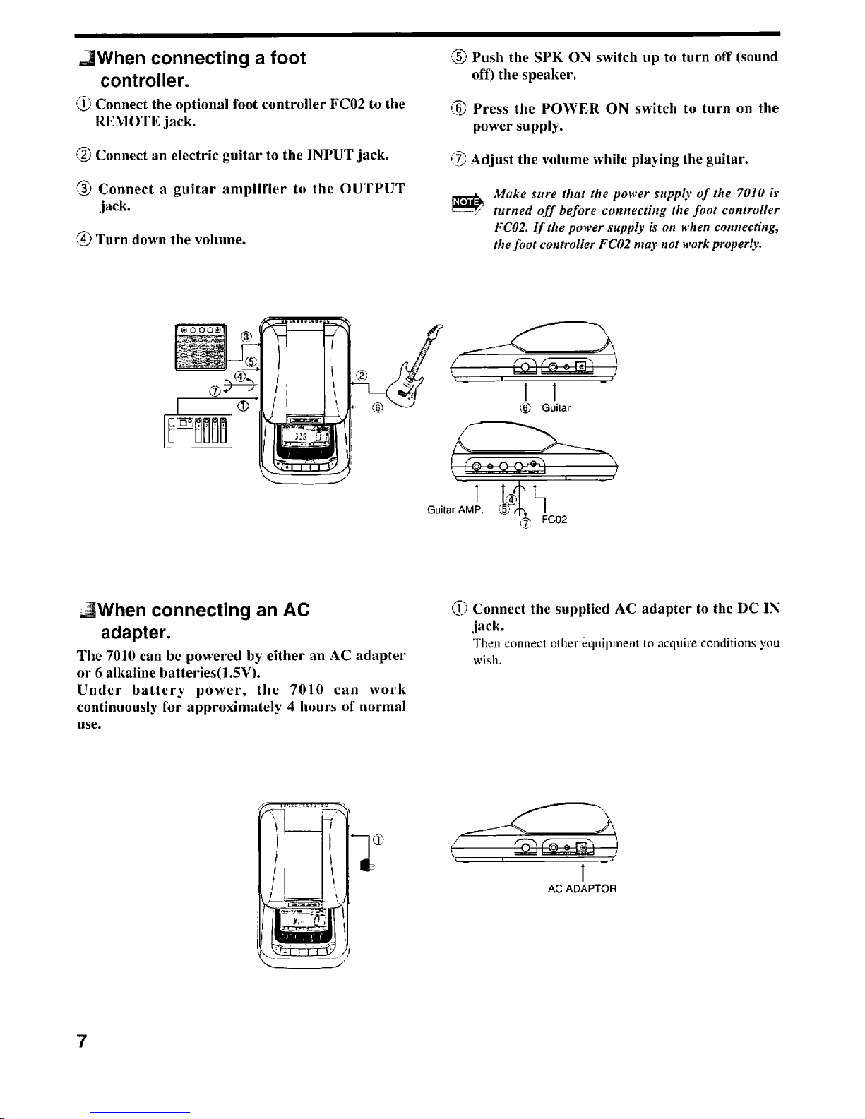
When
connecting
a
li~~tcontroller
7
.........................................................................................
When cnnnec~ingirn
AC
adapter
7
.................................................................................
Getting E'ami1i;lr With Sor~lcIsasic Terms
8
..............................................................................................................
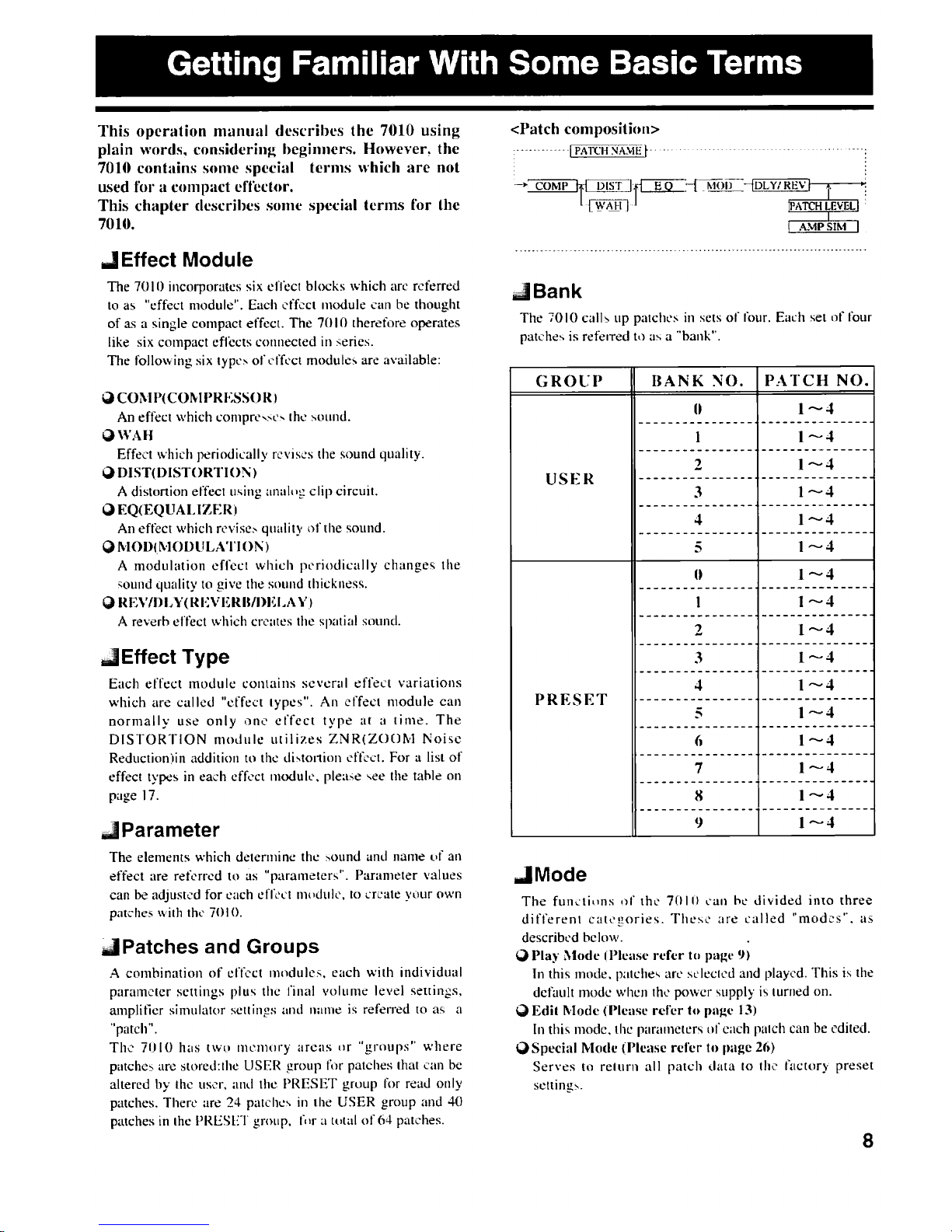
Effect h?lodule
S
.................................................................................................................
EffectType
8
...................................................................................................................
Parameter
S
.................................
............................................................
Pali-he and
G
raups
........
8
Rank
.........................................................................................................................
S
Modc
........................................................................................................................
S
Using the Patct~es(Play hlocie)
..............................................................................................
9
.............................................................................................
Turning on the pc~wcrsupply
9
...............................................................................................
P;mrl Display
in
Play Mode
9
...........................................................................................................
Selecting a Patch
9
...............................................................................................
..\dju\ting the Patch
I,
cvcl 10
..........................................................................................
Turning Effect h*loduleorl/ofl' 10
....................................................................................................
Bypas~ingthe Effects
I1
.......................................................................................................
klulinp the Output
11
........................................................................................................
Tuning the Guitar 12
................................................................................................
GuitarTuner Calihra~io~~ 12
.............................................................................................
Crrating a I'atch (ICclit hlocle)
13
....................................................................................................
Ac~ivati~~gEdit hhdc 13
.............................................................................................
Panel Display in Edit Mock 13
................................................................................................
Editins Efkct Parameter I4
Switching Effect Modules
on
and
off
..................................................................................
1-5
Editing Total Par;rmetes
.................................................................................................
15
...........................................................................................................
Storing a Patch I0
................................................................................
Effect Paranwters ;m1Total I'arameters
17
.................................................................................................
Effect Module
I
.COYIP 17
..................................................................................................
Effect Module 2:WAH 17
........................................................................................
Effect Lfrdule 3.DISTOKTION l8
.....................................................................................................
EffectModulc
4:EQ
20
..................................................................................................
Effect Module
5.Ir.IOD
20
.............................................................................................
Effccthlndule 6.REVIDRY 22
....................................................................................
Total Parameters PATCl
l
LEVIII. 22
...........................................................................................
Ah4P
Slh4 72
.....................................................................................
PATCH
NAME
22
...........................................................................................................
Battery Operation
23
..............................................................................................
Cautions for Dry B;~ttcries 23
.............................................................................................
Installationof Dry Batteries
23
.....................................................................................
Battery Empty Warning lndicalion 73
..........................................................................................................
Sleep
indication
33
.......................................................................................
Operating with the
Ihot
cc~r~trollrr
24
..............................................................................................................
Connections
24
.........................................................................................................
Selecting
:I
Patch
33
.....................................................................................................
Bypassing the Efkc~ 2.1
.......................................................................................................
hluting the Outp~t
24
................................................................................................................
PATCH
LIST
25
..................................................
Returning the 7010
to
1t1efactory preset contlition(Special klnde~
26
.................................................................................................................
Specificatinns 26
1