Studer A523 MK4 Training manual

STUDER
PROTESSIONAT AUDIO EQUIPMENT
.',,,*ririll,litilltr1.ffinilfiit,j1iiii:Flrli#l'illifimtiffifriffi$}'Wlni.''l'qj'ffiffiryT
., ";'
-'fsf,srif'"'ltl*
l"
,dd"iq4r "
OPERATTNG AND SERVICE
TNSTRUCTIONS
A523 Mk4
Professlonal Studlo lrlonltor
Prepared and edited by:
sTL,DtR Professional Aldio AC
lechnical Documentation
Althardstra!5e 30
CH-ol 05 Regensdorf-Switzerla nd
CoPyriSht by STUDER Profetrional Audio AC
Printed in Switzerland
We reserue the right to make aheralionl.
STUDER is a re8istered lrade mark of sTU D[ R Professional Audio AC, RegPsdorf
Otdcr No. 10.27.312t (tD ll95)
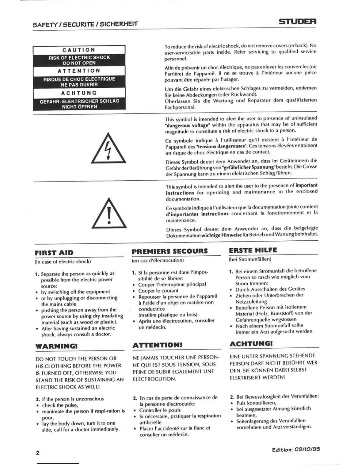
9 AFETY I 9]ECURITE / gICHERHEIT STUI'EFI
To reduce üe risk of electric shock, do not remove coveß (or back). No
urer-seruiceable parß inside. Refer *ruicing to qualified *ruice
percnnel.
Afin de prdvenir un choc 6lectrique, ne pas enlever les couvercls (oü
l'arriörei de l'appareil. ll ne e trouve ä l'int6rieur aucune piöce
pouvant €re 16par6e Par l'usager.
Um die Cefahr eines elektrischen Schlages zu vermeiden, entfernen
Sie keine Abdeckungen (oder Rückwand).
Überlassen Sie die WartunB und Reparatur dem qualifizierten
Fachpersona l.
This symbol is inrended to alert the user to presence of uninsulated
"dangerour vohage' within the apparatus that may be of sufficient
magnitud. to constitute a risk of electtic shock to a pemn'
Ce symbole indique ä I'utilisateur qu'il exislent ä l'int6rieur de
I'appareil des "lensions dangereurcs". Ces tensions 6levdes entrainent
un risque de choc dlectrique en cas de contact.
Diees Svmbol deutet dem Anwender an, dass im Ceräteinnem die
CefahrdärBerührungvon "gefährlicherSpannunS"besteht Die Cröss
der Spannung kann zu einem elektrischen Schlag führen'
This svmbol is intended to alert the user to the presence of importanl
inrtruclionr for operating and mainlenance in the enclosed
documentation.
Ce symbole indique ä l'utilisateur que la documentation jointe contient
dtimporlrnler inslruclions concernant le fonctionnement et la
maintenance.
Dieses Svmbol deutet dem Anwender an, dass die beigelegte
Dokumentation wichtige Hinweise für Betrieb und Wartung beinhaltet'
FIRST AID PREIIIERS SEGOURS ERSTE HILFE
(in cas of elecrlc shmk)
1. Sepamte the peßon as quicklY as
possible lmm the electric Power
surce:
. by switching off the equipment
. or by unpluSSing or disonnectinB
the mains cable
o pushing the penon away from the
power surce by using dry insulating
material (such as wmd or Plastic)'
. After havln8 suslained an electric
shock, always consult a doclol.
wARlllllGt
(en cas d'6lectlocution)
1. Si la percnne est dans I'imPos-
sibilit6 de s libdrer:
. Couper l'interrupteur principal
. Couper le courant
. Repoussr la perrnne de l'appareil
ä l'aide d'un objet en matiöre non
conduclrice
(matiöre plastique ou bois)
. Aprös une dlectmcution, consulter
un mddecin.
ATTENTIONT
(bei Stromunfällen)
1. Bei einem Stromunfall die betroffene
Pemn so rasch wie möglich vom
strom trennen:
. Durch Ausschallen des Cerätes
o Ziehen oder Unterbrechen der
Netzzuleitung
. Betroffene Pemn mit imliertem
Material (Holz, Kunslstoff) von der
Cefahrenquelle wegstossen
r Nach einem Stromunfall rcllte
immer ein Arzt aufgesucht werden.
ACHTUNGI
r)c) NOI TOUCH THT PTRSON OR
HIS CTOTHINC BEFORT THE POWIR
IS TURNTD OFF, OTHIRWIST YOU
STAND THI RISK OF SUSTAININC AN
[rtcTRrc sHocK As wtttl
2. lf the pemn ls unconscious
. check the pulse,
. reanimate the pemn if espi-mtion is
poor,
. lay the body down, tum it to one
side, call for a doctor lmmediately.
2
NT IAMAIS TOUCHTR UNT PTRSON.
Nt QUr EsT SOUS TINSION, SOUS
PTINI DT SUBIR EGATTMTNI UNT
f TTCTROCUTION.
2, [n cas de pene de connaissnce de
la personne 6lectrocutde:
. Contrcller le pouls
o Si ndcesaire, pntiquer la reTiration
anificielle
r Placer l'accident6 sur le flanc et
consulter un mddecin.
EINI UNTER SPANNUNG STEHINDT
PTRSON DART NICHT BERÜHRT WTR-
D[N. SII KÖNNEN DABEI SELB5T
EIEKIRISITRT WIRDTNI
2. Bei Bewusstlosigkeit des Verunfallten:
. Puls kontrcllieren,
. bei ausge€tzter Atmung künstlich
beatmen,
. SeitenlagerunB des Verunfallten
vornehmen und Arzt veßländigen.
EÄi|"ion Ogl1Ol95
STI.DEH gAFETY I SECURITE / gICHERHEIT
Installatlon, Betrleb und Entsorgung
Vorder lnstallation des Cerätes müssen die hieraufgeführten
und auch die weiter in dieserAnleitung mit 2[ bezeichneten
Hinweise gelesen und während der lnstallation und des
Betriebes beachtet werden.
Das Cerät und sein Zubehör ist auf allfällige Transpon-
schäden zu unlersuchen.
Ein CeräL das mechanische Beschädigung aufileist oder in
welches Flüssigkeit oder Gegenstände eingedrungen sind,
darf nicht ans Netz angeschlossen oder muss sofort durch
Ziehen des Netzsteckers vom Netz getrennt werden. Das
Öffnen und lnstandsetzen des Gerätes darf nur von
Fachpersonal unter Einhaltung der geltenden Vorschriften
durchgeführt werden.
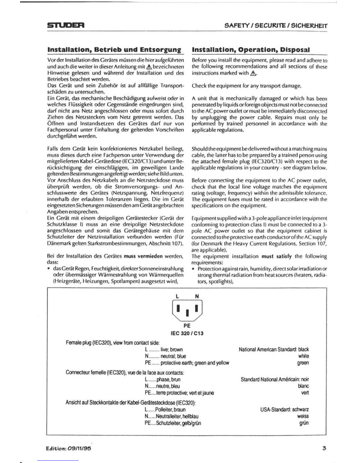
Falls dem Cerät kein konfektioniertes Netzkabel beiliegt,
muss dieses durch eine Fachperson unter Verwendung der
mitgelieferten Kabel-Cerätedose (lEC320/Cl 3) und unter Be-
rücksichtigung der einschlägigen, im geweiligen Lande
geltenden Bestimmungen angefenigtwerden; siehe Bild unten.
Vor Anschluss des Netzkabels an die Netzsteckdose muss
überprüft werden, ob die Stromversorgungs- und An-
schlusswene des Cerätes (Netzspannung, Netzfrequenz)
innerhalb der erlaubten Toleranzen liegen. Die im Cerät
eingesetzten Sicherungen müssen den am Ceät angebrachten
Angaben entsprechen.
Ein Cerät mit einem dreipoligen Cerätestecker (Cerät der
Schutzklasse l) muss an eine dreipolige Netzsteckdose
angeschlossen und somit das Cerätegehäuse mit dem
Schutzleiter der Netzinstallation veöunden werden (Für
Dänemark gelten Starkstrombestimmungen, Abschnitt I 07).
Bei der lnstallation des Cerätes muss vermieden werden,
dass:
. dasCerät Regen, Feuchtigkei! direkterSonneneinstrahlung
oder übermässiger Wärmestrahlung von Wärmequellen
(Heizgeräte, Heizungen, Spotlampen) ausgesetzt wird,
lnstallatlon, Operatlon, Dlsposal
Before you install the equipment, please read and adhere to
the following recommendations and all sections of these
instructions marked with 2[.
Check the equipment for any transport damage.
A unit that is mechanically damaged or which has been
penetrated by liquids orforeign oblectsmust not beconnected
to the AC power outlet or must be immediately disconnected
by unplugging the power cable. Repairs must only be
performed by trained personnel in accordance with the
applicable regulations.
Should theequipment be delivered without a matchingmains
cable, the latter has to be prepared by a trained percon using
the attached female plug (lEC320/C13) with respect to the
applicable regulations in your country - see diagram below.
Before connecting the equipment to the AC power outlet,
check that the local line voltage matches the equipment
rating (voltage, frequency) within the admissible tolerance.
The equipment fus$ must be rated in accordance with the
specifications on the equipment.
Equipment supplied with a 3-poleapplianceinlet (equipment
conforming to protection class l) must be connected to a 3-
pole AC power outlet so that the equipment cabinet is
connectd to the protective earth conductorofthe AC supply
(for Denmark the Heavy Current Regulations, Section '107,
are applicable).
The equipment installation must satisfy the following
requirements:
. Protectionagainstrain, humidity,directsolariradiationor
strong thermal radiation from heat sources (heaten, radia-
tors, spodights),
L l,l
TD
PE
lEc 320 / c13
Female plug (lEC320), view from cofltact sid€:
1........ live: brown
N........ neutBl; Uue
PE...... polective eanh; green and yellorv
Connectzur lemelle (lEC320), u.E de la lace aux contacls:
L.......ptnse, brun
N....,.nsitre, bleu
PE....ten€ potective: ven etjaune
Ansidll auf Steckkontakte der Kabel-Gerätesteckdose (lEC320):
L....,.Polleiter, biaun
N......Nzutnalleiter, hellblau
PE.... $hutzleiter, gBlUgrün
National American Standard: Uack
whle
9re€n
Standard National AmÖricain: ncir
Uanc
vsrl
USA-Standard: sduaz
wdss
grün
Eäitlonz 09I1ll95

äAFETY I 9.ECURITE / gICHERHEIT STUDEH
. die für den Betrieb des Gerätes benöti8te luftzirkulation
beeinträchligt und dadurch die zulässige maximale
tufttempentirr der CeräteumgebunB übeßchritten wird
(!Värmestau),
o die 8elüftungsöffnungen des Gerätes blockien oder
abgedeckt werden.
Das CIerät und seine Verpaclungdarf nursachgerecht entsoryt
werden. Alle Teile des Cerätes, die gefährliche Stoffe
(Quecksilber, Cadmium) enthalten, müssen als Sondermüll
behandelt werden.
Wartung und ReParatur
Durch tntfemen von Cehäuseteilen, Abschirmungen etc.
werden stromführende Teile freigelegt. Aus diesem Crund
müssen u.a. die folgenden Crundsätze beachtet werden:
Eingriffe in das Celät dürfen nur von Fachpersonal unter
Einhaltung der geltenden Vorschriften vorgenommen wer-
den.
Vor Entfernen von Cehäuseteilen muss das Cerät ausgeschaltet
und vom Netz Setrennt werden.
Bei ßeöffnetem, vom Netz Setrennlem Gerät dÜrfen leile mit
ßefä"hrlichen I adungen (2. 6. Kondensatoren, Bildröhren) erst
nach kontrollierter Entladung, heiße Bauteile (teistungs-
halbleiter, Kühlkörper etc.) erst nach deren AbkÜhlen berÜhn
werden.
Bei Wa.lungsarbeilen am geöffnelen, unter NetzsPannunS
stehenden Geräl dürfen blanke Schallungsteile und melalle-
ne Halbleilergehäuse weder direkt noch mit einem nichliso'
lierten Werkzeug berührt werden'
Zusätzliche Gefahren bestehen bei unsachgemässer
Handhabung besonderer Komponenten:
. txplosion-sSefahr bei Lithiumzellen, tlektrolyt-Konden-
satoren und Leistungshalbleitem
. lmplosionsgefahr bäi evakuierten Anzeigeeinheiten
. Strählungs8efahr bei Lasereinheiten (nichtionisierend),
Bi ldröhren (ionisierend)
. VerälzungsSefahr bei Anzeigeeinheiten (LCD) und
Komponenten mit flüssiSem Elektrolyt.
Solche komponenlen dürfen nur von dafür ausgeb.ildetem
Fachpersonil unler Verwendung von vorgeschriebenen
Schu'lzmilleln (u.a. Schulzbrille, Handschuhe) gehandhabt
werden.
für Warlung und Reparalur der sicherheitsrelevanten Teile
des Gerätesdarf nur Ersalzmaterial nach
Herslellerspezifikalion verwendet werden.
Das Cerät muss ordnungsgemäss und regelmässig gewartet
und somit in sicherem Zustand erhalten werden. Bei
ungenügender Wartung oder bei Anderungen der
sicherheitsrelevanten Teile des Ceräles erlischt die ent-
sprechende Produktehaftung des Herstellen.
. Unobstructed air circulation so that the maximum air
temperature in the equipment environment will not be
excded (no heat accumulation),
. Ventilation louven of the equipment must not be blocked
or covered.
The equipment and iß packing malerials should ultimately be
disposed of in accordance wilh the applicable regulalions
only. Parts of the equipment conta ining hazardous substances
(mercury, cadmium) must be treated as toxic waste.
Malntenance and RePalr
The removal of housing parts, shields, etc. exposes energized
parts. For this reason ihe following precautions should be
observed:
Maintenance should only be performed by trained penonnel
in accordance wilh the applicable regulations'
The equipment should be switched off and disconnected
from the AC power outlet before any housing parts are
removed.
Even after the equipment has been disconnected from the
power, parls wilh hazardous charges (e.8. capaciloß, picture
tubes) should only be touched after they have been properly
discharged. Hot components (power semiconduclors, heal
sinks, eic.) should only be touched after they have cooled off'
lf mainlenance is performed on a unil thal is opened and
swilched on, no uninsulated circuil components and melallic
semiconduclor housings should be touched neither with
vour bare hands nor with uninsulaled lools.
bertain components pose additional hazards:
. Explosion hazard from lithium batteries, electrolytic ca-
pacitors and power semiconductors
. implosion hazatd from evacuated display units
. Raäiation hazard from laser units (non-ionizing), picture
tubes (ionizinB)
. Caustic effectbfdisplay units (LCD) and such components
containis liouid eleclrolvte.
Suchcompönents shouldoniy be handled bylrained personnel
who are properly protected (e.g. by goggles, gloves).
For mainlenance work and repair on componenls lhat
influence lhe equipmenl safely. only replacemenl malerial
conforming to ihö manufacturer's specificalions may be
used.
The equipment should be properly sewiced in regular intervals
and bi maintained insafe operatingcondition. lf theequipmml
is not properly maintained or if any modifications are made
to components that influence safety, the manulaclure/s
product liebility Sets void.

STI.IDER E9D
Elektrostatlsche Entladung (ESD) bel
Wartung und Reparatur Electrostatlc Dlscharge (ESD) durlng
Malntenance and Repalr
ATTENTION: Observe precautions for handling devices sensitive to
electrostatic discharge!
ATTENTION: Respecter les prdcautions d'usage concernant la mani-
pulation de composants sensibles ä l'6leclricit6 statique!
ACHTUNG: Vorsichtsmassnahmen bei Handhabung elektrostatisch
entladungsgelährdeter Bauelemente beachten!
Viele lCs und andere Halbleiter sind empfindlich gegen
elektrostatische Entladung (tSD). Unfachgerechte Behand-
lung von Baugruppen mitsolchen Komponenten beiWartung
und Reparaturkann deren Lebensdauerdrastisch vermindern.
Bei der Handhabung der ESD-empfindlichen Komponenten
sind u.a. folgende Regeln zu beachten:
. ESD-empfindliche Komponenten dürfenausschliesslich in
dafür bestimmten und bezeichneten Verpackungen gelagert
und transportien werden.
. Unverpackte, ESD-empfindliche Komponenten dürfen nur
in den dafüreingerichteten Schutzzonen (EPA, z.B. Cebiet
für Feldservice, Reparatur- oder Serviceplatz) gehandhabt
und nur von Personen berührt werden, die durch ein
Handgelenkband mit Serienwiderstand mit dem Masse-
potential des Reparatur- oder Serviceplatzes verbunden
sind. Das gewartete oder repariene Cerät wie auch
Werkzeuge, Hilfsmittel, EPA-taugliche (elektrisch
halbleitende) Arbeis-, Ablage- und Bodenmatren müssen
ebenfalls mit diesem Potential verbunden sein.
o Die Anschlüsse der ESD-empfindlichen Komponenten
dürfen unkontrol I iertweder mit elektrostatisch aulladbaren
(Cefahrvon Spannungsdurchschlag), noch mit meta ll ischen
Oberflächen (Schockentladungsgefahr) in Berührung
kommen.
o Um undefinierte transiente Beanspruchung der Kompo-
nenten und deren eventuelle Beschädigung durch un-
erlaubte Spannung oder Ausgleichsströme zu vermeiden,
dürfen elektrische Verbindungen nur am abgeschalteten
Cerät und nach dem Abbau a llfä ll iger Kondensatorladungen
hergestellt oder gelrennt werden.
Many lCs and semiconductors are sensitive to electrostatic
discharge (ESD). The life of components containing such
elements can be drastically reduced by improper handling
during maintenance and repair work.
Pleaseobserve the following ruleswhen handling ISD sensitive
components:
. ESD sensitive components should only be stored and
transported in the packing material specifically providcd
for this purpose.
. Unpacked ESD sensitive conrponents should only be han-
dled in ESD protected areas (EPA, e.B, area forfield service,
repair or service bench) and only be touched by persons
who wear a wristlet that is connected to the ground
potential of the repa ir or service bench by a series resistor.
The equipment to be repaired or serviced and all tools,
aids, as well as electrically semiconductingwork, storage
and floor mats should also be connecled to this ground
potential.
. Theterminalsof ESDsensitivecomponentsmustnotcome
in uncontrolled contact with electrostatically chargeable
(voltage puncture) or metallic surfaces (discharge shock
haza rd).
. To prevent undefined transient stress of the components
and possible damage due to inadmissible voltages or
compensation currents, electrical connections should only
be established orseparated when theequipment is switched
off and after any capacitor charges have decayed.
Edit.ion: Ogl1Ol95

STUDER
evv|EMC
StörstrahlungundStörlestlskeltElectromagnetlccomPatlblllty
Das Cerät entspricht den schurzanforderungen auf dem The equipment conforms to lhe prolection requiremenls
öäür"]ä"i.f .ttämagnerischen-phinomene, üie u.a. in den relevarir tä electromagnelic_phenomena that are lisled in the
ni.n,f i^i"^ Ognf6/EüC und FCC, Part 15, aufgeführt sind: guidelines 89/336lECand FCC, part l5'
l. Die vom Cerät erzeugten "f"f,rot.gnu,i"t.hen Aus- i. Theelectromagneticinterferencegeneratedbytheequip-
cendunqen sind soweit begrenzt, dass ö bestimmungs- ment is limiled in such a way lhat olher equipment and
;ää;3;il;;;J"ää".ier-""^aiysrememtigtichist. _ systems can be operared 131matlv'
2. Das Cerät weist eine ,ng.rot"nd Festigkeii gegen 2. The equipment is adequalely.protectd against electro-
elektromaqnerische Störu;ß;; ,rf, -ro"d.rt"öin magneiiiinterference so thal il can operale correctly'
bestimmun[sgemässer Belrieb miflich ist'
Dr;ä;t;;r"#g;t*i"t una urrütit oie Bedingungen d.er im The unit has been tested and confotms to the EMc slandards
Kapirel .Iechnische Daten" ,rh"ftfrrr"n rüv-Standards. aoolicable to residential, commercial and light industry' as
ö]ä"ii.iriää itJ"i i""J'ar'?";;;i;i"^ 'it utn"' tilied in ttre secrion ,,lechnical Data"' The limiu of these
;;;;;;;;;.^ wrtr.r.tr"tnti.trl"f,io*otti"in"^ s.ttrrt 0", standards reasonably ensure proteclion of the environment
UmgebungwieauctrenrsprectrenjeitOrfestigkeirdesCerares. and corresponding noise immunity of the equipment'
tine absolute Carantie, Oass tJne ,n"Aiubte elektroma- However, ii is not.ibsolutely warranled that the equipment
snerische Beeinrrächtipunß *äü;";J J"t C;rätebetriebes willnotbäadverselyaffectedbyelectromagneticinlerference
8"itr"t'r, itr;"ao.h nlcXt grteben. drrrins ooeration'
tJm die wahrscheinlichkeir -sälche, Beeinrrächtigung To miniÄize rhe probability.of eleclromagnelic interference
weirgehend auszuscntiessen, siniJ.al fo-lgende t"lass nah".eX as far as possible, the following recommendations should be
zu bäachten: ' followed:
. tnsrailieren sie das cerär gemäss den Angaben.in_der . lnstall the "9Yip11.l! li-T:"f^.-T:^Y:tl the operatinS
äJi"n"r,grr"f"itrng, undvänvendenSiedaimitgelieferte instructions. Use the suppl'ed accessorres'
Zubehör.
. Verwenden Sie im System und in der Umgebung in denen ' ln the system and in the vicinity where the equipmenl is
das cerär eingesetzr ir,, ^rr'iöä^ä"ninnrrgun, rnstaiteä, use only components (systems, equipment) that
ääei"i, Oi" inrärreis die nnfoäeiunien deroben e*ätn- also fulfill the above LMC standards'
. Use a syslem grounding concept that satisfies the safety
reouirements (prolection class I equipment must be con-
neöted wirh a protecliveground conductor) that alsotakes
into considerition the tMC requirements' when decidinB
between radial, surface or combined grounding the ad-
vantages and disadva ntages should be careful ly evaluated
in each case.
. Use shielded cables where shielding is specified' The
connection of the shield to the corresponding connector
terminal or housing slrould have a large-surface and be
corrosion-proof. Plöase note that a cable shicld connected
onlv sinsle-endcd can act as a lransmilting or recelvlng
intännt"t".g. with an effective cable length of 5 m' the
freouencv ii above 1o MHz) and lhal the edges of the
dieital cbmmunicalion siSnals cause high-frequency
raäiation (e.g. [S or HC logic up lo 30 MHz)'
. Avoid current loops or reduce their adverse effects by
keeoins the loop sürface as small as possible, and reduce
the hoiie curreÄr flowing through the loop by.inserting an
adtlitional impedance (e.9. common-mode relecllon
choke).
ten Standards erfüllen.
. Sehen Sie ein Erdungskonzept des Systems vor, das sowohl
die Sicherheiuanforüerungen (die Erdung derCeräte gemäss
Schutzklasse I mit einem-schutzleiter muss gewährleislet
5gin), wi€ auch die EMv-Belange berücksichliSl' Bei der
tntscheidung zwischen stem- oder flächenförmiger bzw'
kombinieneiErdung sind Vor- und Nachteile gegeneinan-
der abzuwägen.
o Benutzen Sü abgeschirmte Kabel für die Veöindungen,
für welche eine Äbschirmung vorgesehen ist' Achten.Sie
auf einwandfreie, grossfl ächige, konosionsbeständige
Veöi ndung der Abschirmung zum entsptechenden Slecker-
anschluss 6zw. zum Steckergehäuse. Beachten Sie, dass
einenuran einem EndeanBesahlossene Kabelabschirmung
als Sende- bzw. Empfangiantenne wi*en kann (z'B' bei
wirksamer Kabellänge v6n 5 m obeöalb von l0 MHz),
und dass die Flanken-derdigitalen Kommunikationssignale
hochfrequente Aussendunigen verursachen (z'B' LS- oder
HC-Loeik bis 30 MHz).
. Vermeidm Sie BildungvonStromschleifenodervermindem
Sie deren unerwünsöhte Auswirkunp indem Sie deren
Fläche miulichst klein halten und den darin fliessenden
Slrom durc"h tinfü8en einer lmpedanz (2.8. Cleichtakt-
drossel) reduzieren.
6Edilion: Ogl1Ol95
STT.DEH Ttonf
o rmltälea rklä run
gc n I D c ca at tt,lon. of Conforrnlüy
Class A Equlpment - FCC Notlce
This equipment has been tested and found to comply with the limits for a Class A digital device, pursuant to Part l5 of
the FCC Rules. These limits are designed to provide a reasonable protection against harmful interference when the
equipment is_operated in a commercial environment. This equipment generates, uses, and can radiate radio frequency
energy and, ifnot installed and used in accordancewith the instruction manual, may cause harmful interference tö radiö
communications. Operation of this equipment in a residential area is likely to cause harmful interference in which case
the user will be required to correcl the interference at his own expense.
Caution:
Any changes or modificätions not expressly approved by the manufacturer could void the user's authority lo operate
the equiprnent, Also refer to relevant information in this manual.
G E-Konlorm ltätserklärunt GE Declaratlon ol Gonforrnlty
Der Hersteller,
RELEC S.A.,
CH-1400 Yverdon,
erklärt in eigena Verantwortun& dass das in dieser Anleitung
beschriebene Produkt
o Studer A523 Mk4, Professional Studio Monitor,
auf das sich diese Erklärung bezieht, entsprechend den
Bestimmungen der EU-Richtlinien und deren Ergänzungen
. Nieder+annung:
73n3/EWC,93/6WEWC
o Elektromagnetische Verträglichkeit (EMV):
89/336/EWC + 92/31 lEW C + 93 /68/EWA
mit den folgenden Normen und normativen Dokumenten
übereinstimmt:
o Sicherheit:
Class l, EN 60065/1 993; IEC 65/1 985
o EMV:
EN 50081-1/1992; EN 50082-1/1992
Yverdon, 6. November 1 995
The manufacturer,
RELEC S.A.,
CH-1 400 Yverdon,
declares under his sole responsibility that the product
described in this manual
o Studer A523 Mk4, Professional Studio Monitor,
to which this declaration relates, according to following
regulations of EU directives and amendments
o Low Voltage (LVD):
7323/EEC + 93/6AEEC
. ElectromagneticCompatibility(EMC):
89/33UEEC + 92/31 lEEC + 93/68/EEC
is in conformity with the following standards or other
normative documents:
o SafeV:
Class l, EN 60065/1 993; IEC 65/1 985
o EMC:
EN 50081-1/1992; EN 50082-1/1992
Yverdon, November 6, 1 995
w
Alain Roux, Director
%.. I
Alain Roux, Direktor
Eäitlon:07l11l*5
5TT'I'EH
A523Mk4
Features
a
a
a
a
Active two-way monitor sPeaker
Compact size
High sound pressure level of 103 dB SPL
Suited as a near field monitor in the following applications requir-
ing competent monitoring without long installation procedures:
- Control and editing rooms
- Schools
- Audio-visual demonstrations
- Home recording studios
Thanks to low mJgnetic dispersion sound transducers and addi-
tional screening oieration isalso possible in areas where speaker-
induced magnötic fields would produce interference:
Next to video terminals, measurement instruments, etc'
Built-in power line filter
Built-in overload protection
Electronically balanced inPut
XLR input terminal
Front panel volume control
Lineai frequency response due to ,,active processing"
Equipped *ith rnounting bracket and threaded bushing, e'g' for
installation on microPhone stand
a
o
o
O
a
a
a
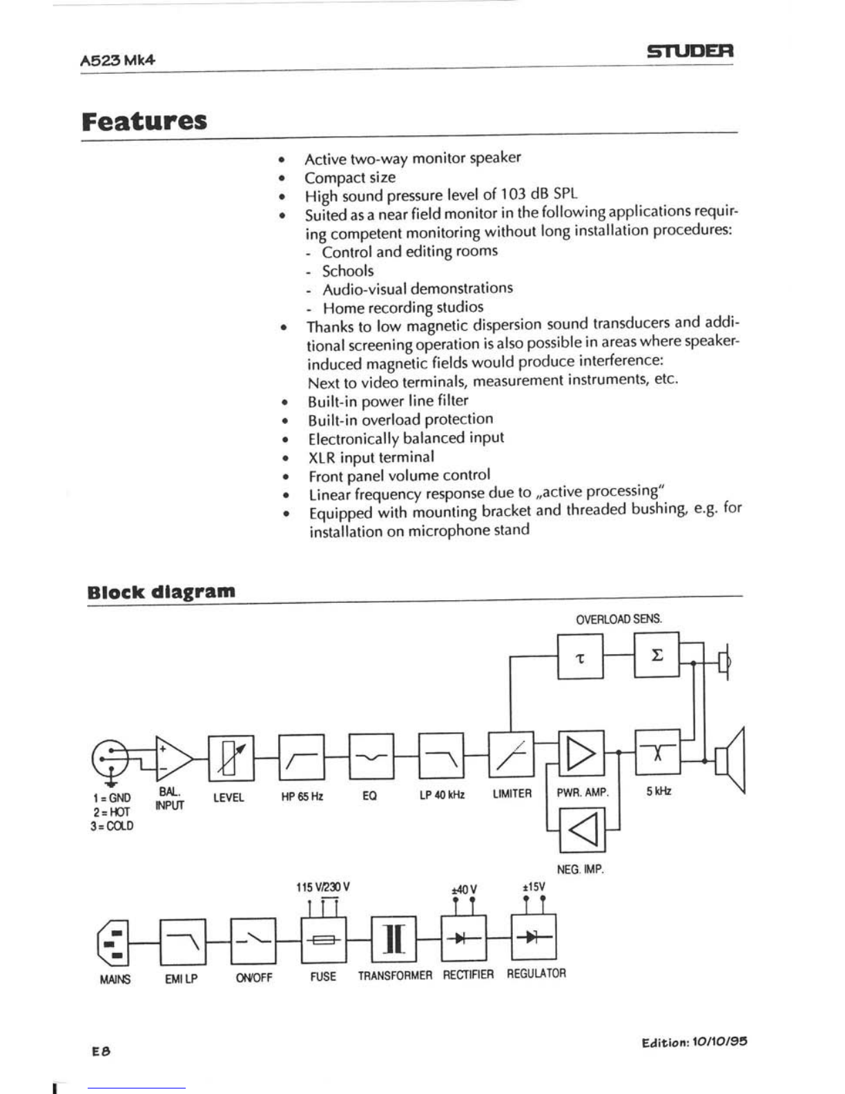
Block rllagrarn
OVERLOAD SA{S.
NEG. IMP.
I =GNO
2:t$r
3 = COLD ff LEvEL
r
t15VzSV
TRANSFORMER RECTIFIER REGULATOR
Eäiliont 10l1Ol95

STUDEH A523Mk4
Gonnectlons
Power connectlon
A
A
Before connecting the speaker to the AC supply, read the,,Secu-
rity" section at the beginning of this manual.
Make sure the line voltage selector is in the correct position.
Match the primary fuse to the line voltage in accordance with
the information on the rear panel. lnstall the correctly rated fuse
in lhe line voltage selector insert.
Audlo conncctlon
Balanced operat
lxl
g
For unbalanced
ion uses the following pin assignment:
1 =CND
2=HOT
3 = COLD
operation the following wiring may be used:
Eäitlon:10l1Ol95

A5?-9Mk4 sTT'DEll
Appllcatlons
Free-standing sel-up:
Microphone stand:
lnstallation:
Scr6w ls fitl€d with lock-nul. For
romoving the brackel firsl loosen
the lock-nut b€lw€on lhe brack€l
end lhe cablnst.
Elition?Sl1Ol95
sTUtrEH A523Mk4
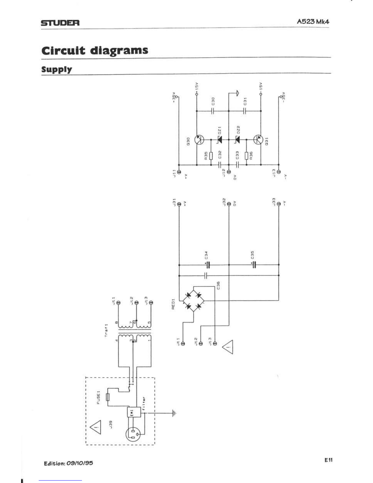
Glrcult dlagrams
oo
o
rt /n
h@
&
l
I
-#lr'
Editlon: 09l1Ol95

A5?3Mk4 STUDER
Processlngr controls
" r;+
i qö r
EÄ|t-ion: OgllOl95

STUEEH A523Mk4
Ampllfler
?
E
t
"1
c)
öt
o
00
'E
;o
oJ(!
!o'
.. :? CL
U^
v
\ _ fiE
e{ i.rü.
. d U'-
X ":'=g
t -r d=
$ 3= I
ö d x'0
r Itu
S e oi€
Y o-i..
: 'a-;
€ ü? r
i th-c
: ..-F-
* O tO
!l -.-:.
cFt,
O o* 9
=q-oa
96^.v
E e ü &"E
E ;- 'u; .,
E'v E Zi
E-EäöE
= Eä - z
a I >?* 2
F Or)* E
rJ-IJ.=E
JQr'llX
F,6 Y aE
ö = o-o o
.=FU<E
C/-öi d; Z
El3
Edition:1611O195

A5?,5Mk4 STUDEH
PGB layouts
P*mfiiffinm?esem,'
:üffiHffin
f ftm-cffiH+'s
I 6-f6iTiOrT -EriF "'
EHHtffiffittWffiHnnH
@Jl3

STUOEH A5?3Mk4
Parts llst
Item Value Specs Item Value Specs Item Value Specs
C0 mt us€d
Ct 22 p/63 V
C2 17n
c3 '100 p
c4 ln
C5 ln
CO 220n
C7 22pl€3v
C8 22 y/63 V
C30 220n
C3l 220^
C32 220n
C33 220n.
C34 3300 p/50 V
C35 3300 p/50 V
C36 lm n
C41 22 p63 V
C42 100p
C43 221!63V
C44 220p
C45 nol ussd
C50 22Vl63U
C52 220p
C63 220n
C68 220n
C72 100p
C73 nol usod
C71 not usod
C76 nol usod
C78 nol us€d
C79 nol us€d
c8o 22]r/63V
C81 170 pl16 v
Cl02 not used
Cll f 22pl63V
FCl 3,3 /250 V
FC2 1,7 tr/400 V
Dl RP1O4
02 RP104
D3 RP1O4
D4 RP1O4
D5 not used
D8 not us6d
Dg not us€d
091 RPt01
D92 wire bddge
D93 RP101
094 wiro bridge
Dt tl RPt04
0112 RPIOI
DZ1 BZV 85
DZ2 BZV 85
LEDoI gro€n
LED03 nol used
RED1 80 V/4 A
FLt 0,33 mH
Edi'-ion:16110l95
Elsdrolyllc radlal
PE 7.5 mm
Csramlc
PE 7.5 mm
PE 7.5 mm
PE 7.5 mm
Elsclroly'lic radial
Eleclroly'tic radial
PE 7.5 mm
PE 7.5 mm
PE 7.5 mm
PE 7.5 mm
El€clrolytlc radlal
El€clroly,lic radlal
PE 7.5 mm
ElodroMic radial
Coramic
El€clrolylic radial
c6ramic
Elsclrolyllc radial
Coramlc
PE 7.5 mm
PE 7.5 mm
Coramic
(lor US end Canadat
01 BC546B NPN
Q2 BC556B PNP
03 8C5468 NPN
04 BC556B PNP
05 BC546B NPN
Q6 BC556B PNP
07 8C5468 NPN
Og nol ussd
Q9 BD241C NPN
or0 go242c PNP
OII TIPIa2 NPN
016 IIP127 PNP
o17 It?122 NPN
or8 ltP127 PNP
OI9 IIPIl2 NPN
O3O TIP122 NPN
Q31 IIP127 PNP
ol'tl Bst70 FET
Ol 12 nol used
R2 1k 0.5W
R3 tk 0.5w
R6 100 0.5 w
R7 100 0.5 W
R8 330 0.5 W
R9 330 0.5W
812 1k 0.5w
R13 22R 0.5 W
R14 2,7 k 0.s w
R15 22 k 0.s w
R18 1 2W
R19 1 2W
R20 1 2W
R2't 1 2W
n22 't 2W
R23 I 2W
824 10 k 0.5 w
R25 3,3 k 0.5 W
R26 47 0.s W
A27 47 0.5 W
R28 47 0.5 W
R29 47 0.5 W
R30 22 \ 0.5 w
R31 330 k 0.5 w
832 nol used
R33 22k 0.5W
R35 10 k 0.s w
R36 10 k 0.5 W
H10 wiro bridgo
B4r 33 k 0.5 W
442 22 k 0.5 W
R43 15 k 0.5 W
F44 10 k 0.5 W
R48 56 k
R49 not us€d
n51 4.7 k
R52 10 k
R53 wirs bridge
R54 1k
Rss 2,2 k
R64 56 k
R66 2,2 k
R68 nol us€d
R70 nol used
R7't 10 k
472 10 k
873 nol us€d
471 Ik
R75 nol ussd
R76 nol ussd
A77 wire bridge
R78 nol us€d
R79 not used
R81 33 k
R82 33 k
R83 33 k
R84 47
R85 220
R86 1k
887 47
R91 2,21
n92 nol ussd
893 8,2 k
R94 nol us€d
RSs 470
R10t 10 k
R102 22k
Rl03 10 k
R104 1 k
R105 1 k
R't11 220
Rl12 15 k
R113 330 k
Rt14 nol us€d
FBl wire bridge
FUSE'I T100mA L 250V 5)40mm(230V) F45 nolus€d
or T800mA L 250V 5e0mm(115V) R46 notusod
ot f 800 nA slow blow UUCSA, 5x20 mn R47 100 k0.5 w
0,5 w
0.5 w
0.5 w
0.5 w
0.5 w
0.5 w
0.5 w
0.5 w
0.5 w
0.5 w
0.5 w
0.5 w
0.5 w
0,5 w
0.5 w
0.5 w
0.5 w
0.5 w
0.5 W
0.5 w
0.5 W
0.5 w
0.5 W
0.5 W
0.5 W
0.5 W
0.5 W
0.5 W
Eledrolylic radial
Elsclrolylic arial
Elsclrolylic radial
PP arial
PP arial
tasl recovsry
last recovsry
lasl rocovery
last r€covery
lasl rocovsry
last recovory
lasl recovsry
lasl recovery
15 V Z€ns
l5 V Z€net
Bridg€ rsclifisr
RT1 I k Trimm€r
RPI '10 k Polenliomelsr
PTCI not ussd
SW1 nol used
Trall 2 x 25 V/50 VA Mains transfomor
Ul TL072CP 0ual oPamP
U2 TL072CP Dual opamp
U3 IL072CP oual oPamP
E15

A5.?3M).4 sTl"DEll
Technlcal sPeclflcatlons A 52 3 lllk4 ll"iff"il3,eJ.T"
Sound pressure lwel
Frequency response
Harmonic distortion
Input lmpedance
SensitivitY
Max. input level
Power supply
Primary fuse
Mains frequency
Power consumption
Openling conditions
Dimensions
Weight
Chassis diameters
Safety standarrd
EMC standards
Spurious radiation
Noise immunity
max. 103 dB SPt 1 m in a low-reflection room, 1 kHz
warbled with 100 Hz
65 H2...20 kHz -6 dB 1 kHz sine wave, -6 dB,
7OH2...18 kHz t3 dB
<2olo (86 dB SPL) 100 H2...10 kHz;'l m;
low-reverberant room
XtR-3f connector, electronically balanced; pin 2 hot
36 kn
0 dBu (e 775 mY) for 100 dB SPL
Continuously adjustable with potentiometer from 0 dB'..--.
+10 dBu (s2,45 Y)
115 V(100 V...130 V)
230 V(198 V*.244V)
1 15V: T800 mA [250 V 5 x 20 mm
230 V T400 mA 1250 V 5 x 20 mm
USNCanada: T 800 mAslow blow UUCSA, 5 x 20 mm
50...60 Hz
8...50 VA
+1 0...+40'C ambient air temperature
Relative humidity: max.95% annual mean, max.75t", non-con-
densing (DlN 40 040, class F)
162x242x162mm(WxHxD)
4.5 kg (with mounting bracket)
102 mm (woofer)
20 mm (tweeter)
EN 60065/lEC 65, class I
lndividual test High-voltage test AC 1,5k VRMS
EN 50 o8t-1
EN 50 082-1
Spare Parts
EäitiomOTllll9S
Tweeter Mk4
Woofer Mk4
Heatsink compl. with power supply
and main board Mk4
Order No. I 5.056.006.00
Order No. 1 5.056.007.00
Order No. 1 5.056.008.00
Table of contents
Other Studer Speakers manuals


