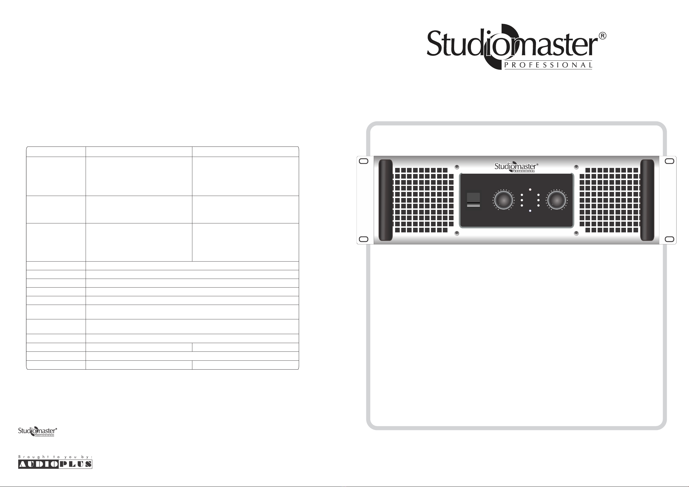
Studiomaster Professional RAX 5020 User manual
Instruction Manual
Stereo Power Amplifier
A series of high output, high quality stereo power amplifiers offering greater reliability for a wide
range of Clubs, Stage and P.A. applications.
Features. . .
• Rugged & Reliable Stereo Power Amplifier.
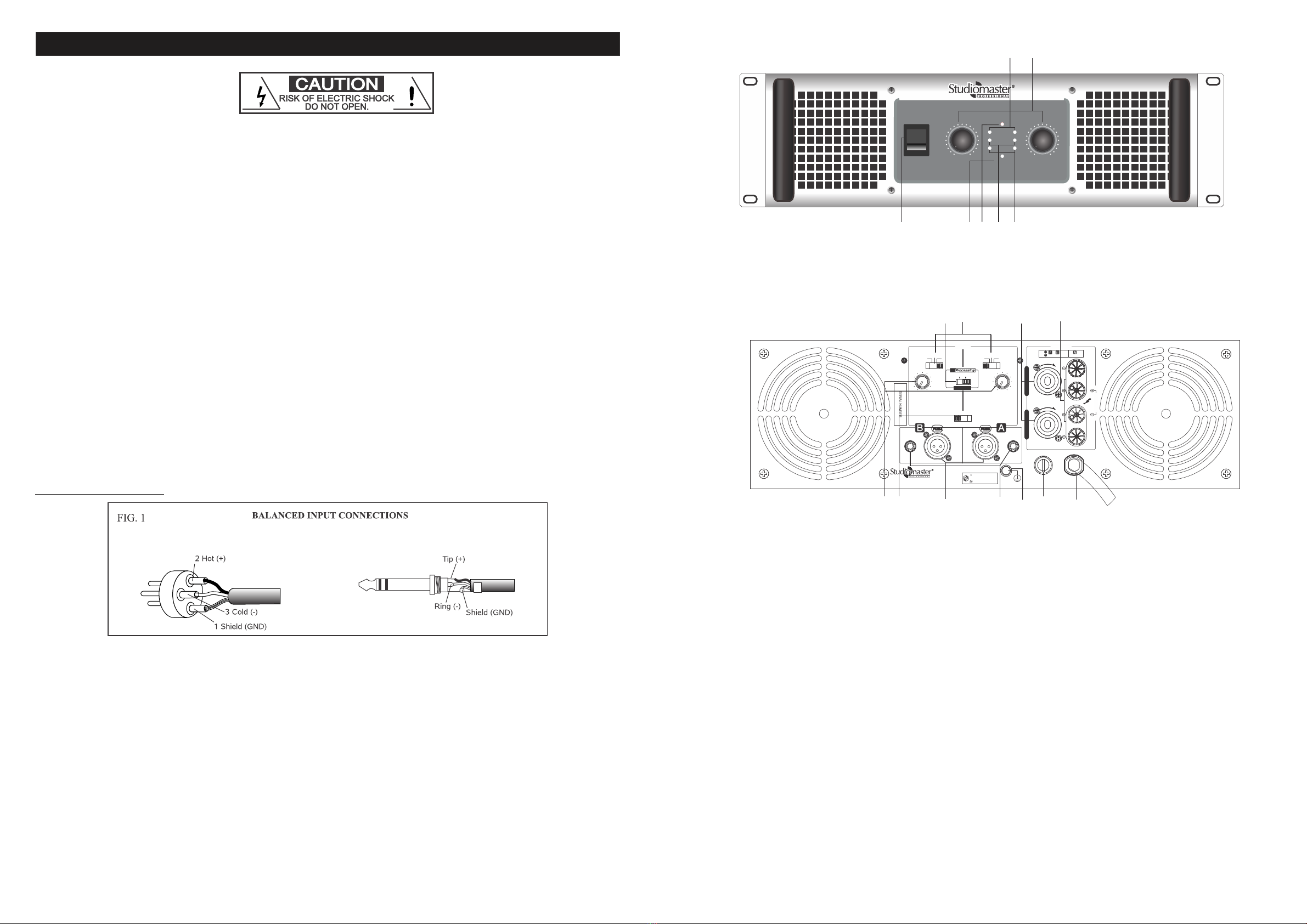
• Output: Speakon, 6.3mm jack socket & Binding Post Connectors.
• EQ Processing, Low Cut, Subwoofer on rear Panel.
• Temperature controlled Fans.
• 19” 3U Rack Mountable design.
• Input: Balanced XLR & 1/4” Jack.
• Level Control & LED indicators (Power, Signal, Clip, Bass Boost & Protect) on front panel.
• Stereo, Bridge & Mono Mode Selection Switch.
• Protection: Temperature DC, Short Circuit.
• Mains voltage operation 220VAC-240VAC as well as Low Voltage Operation (150VAC).
For reliable and trouble free operation, please observe the following points:
• Ensure all input / output connections are correct and secure.
• The handling capacity of the loudspeakers is adequate for the output of the amplifier.
• Always install the amplifier in a well ventilated location.
• Protect unit from severe shocks.
4. Turn gain controls to minimum , switch on the amplifier and the Blue power LED will illuminate.
6. Protect LED. These power amplifiers feature unique DC, thermal protection circuit.
1. Connect loudspeaker system (MINIMUM load 2 ohms) with sufficient handling capacity to the output terminals of the amplifier.
2. Connect output from mixer ( or any other suitable signal source) to the appropriate input sockets of the power amplifier.
NOTE. All inputs are BALANCED and connections for the XLR input are Pin 1 = GND, 2=HOT, 3= COLD
3. Connect the power cord to the mains.
OPERATION
Models: RAX-5020, RAX-7020
Do not make any changes to the unit. This would also void your warranty.
The warranty is not applicable in case of accidents or damages caused by inappropriate use or disrespect of
the warnings contained in this manual. Studiomaster Professional can not be held responsible for personal
injuries caused by a disrespect of the safety recommendations and warnings. This is also applicable to all
damages in whatever form.
Rev000/SM RAX SERIES/JUNE 2019
SPECIFICATIONS
Model
Bridged 4Ω (5600W RMS)
8Ω (3800W RMS)
4Ω (7600W EIA)
8Ω (5000W EIA)
4Ω (7000W RMS)
8Ω (4800W RMS)
4Ω (9000W EIA)
8Ω (6200W EIA)
2Ω (2 x 2800W RMS)
4Ω (2 x 1900W RMS)
8Ω (2 x 1200W RMS)
2Ω (2 x 3700W EIA)
4Ω (2 x 2500W EIA)
8Ω (2 x 1400W EIA)
RAX 5020 RAX 7020
Input Impedance
Protection
Indicators
Dimensions (WxDxH)
Net Weight in Kg*
Single channel driven
Damping factor
Frequency Response
Cooling
Power Supply
2Ω (3000W RMS)
4Ω (2100W RMS)
8Ω (1280W RMS)
2Ω (3800W EIA)
4Ω (2800W EIA)
8Ω (1600W EIA)
2Ω (3600W RMS)
4Ω (2500W RMS)
8Ω (1500W RMS)
2Ω (4700W EIA)
4Ω (3250W EIA)
8Ω (1950W EIA)
Input Connector
(per channel)
Output Connector
(per channel)
Power, Signal, Clip, Bass boost & Protect
>350:1 (8Ω)
20Hz-20KHz (-3dB)
20KΩ Balanced/10KΩ Unbalanced
Temperature, DC short circuit, Soft-Start
XLR, Jack Stereo 6.3mm
32.0 kg 34.0 kg
482 x 133 x 527mm (3U)
Speak-on connector/
Binding Posts
2 x Variable Speed fans (120MM)
240V 50Hz,25A, 6050W 240V 50Hz,30A, 6550W
5. Adjust gain controls to required level. NOTE. If the audio input signal is too high, distortion will result and the CLIP indicator
will light. If the clip LED is lit permanently or flashes, the gain level should be reduced.
*Disclaimer: Above weight may vary within +/-0.5Kg.
A1/A2, Giriraj Industrial Estate, Mahakali Caves Road, Andheri (East), Mumbai - 400 093 India.
Tel.: +91-22-42869000 / 001 / Fax: +91-22-26871453 Whats App.: +91-8879028079
E info@audioplus-india.com W www.studiomasterprofessional.com / www.audioplus-india.com
* Design and specification are subject to change without notice
is a registered trademark of Audioplus in India. © Copyright Audioplus, 2008. All rights reserved.
Any unauthorised reproduction or use of logos, images or design elements is strictly prohibited by law. No part of the
compilation may be reproduced in any manner or translated without written permission.
0 10
CLIP
SIGNAL
PROTECT
POWER
BASS BOOST
CH A
0 10
CH B
O
I
POWER
• Stable 2ohm operation.
2Ω (2 x 3500W RMS)
4Ω (2 x 2400W RMS)
8Ω (2 x 1400W RMS)
2Ω (2 x 4500W EIA)
4Ω (2 x 3100W EIA)
8Ω (2 x 1800W EIA)
Stereo
Made in P.R.C.
*info@audioplus-india.com
91-8879028079
+91-22-42869000 / 001
OUTPUT
C
K
L
O
C
K
L
O
STEREO
BRIDGE
MONO
EQ
C
H
A
N
N
E
L
A
C
H
A
N
N
E
L
B
BASS BOOST
FREQUENCY (Hz)
120
63 140
43 180
OFF
LOW
CUT
SUB LOW
CUT
OFF
SUB
OFF
ON
B
R
I
D
G
E
FREQUENCY (Hz)
120
63 140
43 18 0
CHANNELCHANNEL
1+
1- &
STEREO/MONO
2+
2- BRIDGE
INPUT
0 10
CLIP
SIGNAL
PROTECT
POWER
BASS BOOST
CH A
0 10
CH B
O
I
POWER
2 3
INTRODUCTION
INSTRUCTION MANUAL - STEREO POWER AMPLIFIERS
WARNING :
THIS UNIT MUST BE EARTHED.
KEEP WELL VENTILATED.
Thank you for purchasing the Studiomaster Professional RAX series amplifier. These RAX series amplifier incorporate
Studiomaster Professional renowned technological expertise, and offers high reliability, rock-solid stability, and superb
acoustic characteristics.
INSTALLATION
• Connect this unit’s power cord only to an AC outlet of the type stated in this Instruction Manual or as marked on the unit.
Failure to do so is a fire and electrical shock hazard.
• Do not allow water to enter this unit or allow the unit to become wet this may result in Fire or electrical shock.
• Do not place a container with liquid or small metal objects on top of this unit. Liquid or metal objects inside this unit are a fire
and electrical shock hazard.
• Do not place heavy objects, including this unit, on top of the power cord. A damaged power cord is a fire and electrical shock hazard.
• Be sure to connect to an appropriate outlet with a protective grounding connection. Improper grounding can result in
electrical shock.
OPERATION
FEATURES
• Do not scratch, bend, twist, pull, or heat the power cord. A damaged power cord is a fire and electrical shock hazard.
• Do not remove the unit’s cover. You could receive an electrical shock. If you think internal inspection, maintenance, or repair
is necessary, please contact your dealer.
For correct operation
Connector pin assignments • XLR-type connectors are wired as follows Pin 1: ground; Pin 2: hot (+); in 3: cold (-)
Always turn the power off when the amplifier is not in use.
Illustrations in this manual are for explanatory purposes only, and may not match the actual appearance of the product during operation.
• Do not modify the unit. Doing so is a fire and electrical shock hazard.
• If lightning begins to occur, turn off the power switch of the unit as soon as possible, and unplug the power cable plug from
the electricity outlet.
• If there is a possibility of lightning, do not touch the power cable plug if it is still connected. Doing so may be an electrical
shock hazard.
• With two types of input jacks (balanced XLR & 1/4” Jack) and 2 types of output jacks, (Speakon, binding post). These amplifiers
are suitable for a wide variety of applications and installed systems.
• The unit offers three operating modes: STEREO (where Channels A & B operate independently), MONO (where the unit
outputs a mono source though twin amplifier systems), and BRIDGE (where the unit operates as a single high-power amplifier)
• Each channel is equipped with an independent LOW CUT/SUB WOOFER switch-where LOW CUT engages a high-pass filter,
and SUB WOOFER engages a low-pass filter. With LOW CUT or SUB WOOFER selected, you can adjust the cutoff frequency
from 43Hz to 180Hz.
• The PROTECTION indicator lights up-and sound output is automatically muted-whenever the unit’s protective circuitry is
operating i.e. thermal and DC protection.
• Each channel has a common bass boost switch, when turned ON, the amplifier adds low-frequency compensation so that
the speaker output is enhanced.
FRONT PANEL
• Each channel has its own SIGNAL and CLIP indicators.
• Variable-speed low-noise fans ensure the amplifiers run cool.
2. Balanced 6.3 mm jack input - This stereo jack connector takes the signal (balanced/unbalanced) for driving the channel. If the signal
is unbalanced, a mono connector may be used.
1. Balanced XLR input - This XLR connector takes the signal (balanced/unbalanced) for driving the channel. If the signal is unbalanced,
pin 2 can be used for the signal and pin 3 connected to the earth.
5. Bass Boost Switch - If you set this switch ON, the amplifier adds low-frequency compensation so as to enhance speaker output. The
results (the actual change in the low-frequency balance) will vary according to the speaker type. Note that this switch is effective only
if the FILTER switch is set to OFF.
6. Configuration Switch - This 3 way switch configure the amp for the three working modes Mono, Stereo and Bridge.
7. Output Binding Post - Use this output for picking up the amplified signals individually for stereo mode & in combination for bridge
mode.
8. Speakon connector for CH A to CH B - Use this connector to pick amplified output of CH A & CH B.
9. Fuse holder socket. Replace fuse with same type & rating.
10. Power cable - Use this cable for supplying power to unit.
3. Frequency adjustment knob - When the EQ is selected between Low Cut & Sub woofer, use this knob to adjust the frequency.
4. Filter Switch - Use this switch to select the filter type. SUB WOOFER......Use a low-pass filter. The amplifier outputs the frequencies
that are lower than the cut-off set by the FREQUENCY adjustment knob. LOW CUT......Use a high-pass filter. You can use this setting
to filter out unneeded low or subsonic frequencies.
11. External earth terminal: For a possible ground connection (e.g. in case of hum problems).
1. Power ON/OFF switch 2. Power on/off LED indicator 3. Protect indicators for CH A & CH B
4. CH A & CH B gain control 5. Signal LED indicators for CH A & CH B 6. Clip LED indicators for CH A & CH B
7. Bass boost indication
REAR PANEL
6
4
5
13
27
XLR CONNECTOR STEREO JACK 6.3mm 1/4”
3 6 1
2
9 10
11
4
587
This manual suits for next models
1
Other Studiomaster Professional Amplifier manuals

Studiomaster Professional
Studiomaster Professional ARC Series User manual

Studiomaster Professional
Studiomaster Professional XPA Series User manual

Studiomaster Professional
Studiomaster Professional DPA 2000 User manual

Studiomaster Professional
Studiomaster Professional XPA 40 User manual

Studiomaster Professional
Studiomaster Professional PA Series User manual

Studiomaster Professional
Studiomaster Professional XJA 2600 User manual


