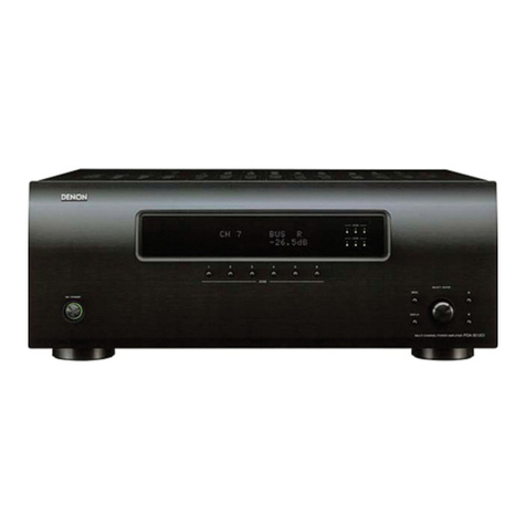
Denon POA-A1HDCI User manual

Denon Brand Company, D&M Holdings lnc.
e
●For purposes of improvement, specifications and
design are subject to change without notice.
●Please use this service manual with referring to the
operating instructions without fail.
●Some illustrations using in this service manual are
slightly different from the actual set.
注 意
サービスをおこなう前に、このサービスマニュアルを
必ずお読みください。本機は、火災、感電、けがなど
に対する安全性を確保するために、さまざまな配慮を
おこなっており、また法的には「電気用品安全法」に
もとづき、所定の許可を得て製造されております。
従ってサービスをおこなう際は、これらの安全性が維
持されるよう、このサービスマニュアルに記載されて
いる注意事項を必ずお守りください。
●本機の仕様は性能改良のため、予告なく変更すること
があります。
●補修用性能部品の保有期間は、製造打切後 8 年です。
●修理の際は、必ず取扱説明書を参照の上、作業を行っ
てください。
●本文中に使用しているイラストは、説明の都合上現物
と多少異なる場合があります。
X0367V.02 DE/CDM 0801
SERVICE MANUAL
STEREO POWER AMPLIFER
MODEL JP EU E2 EK E2A E1C E1K EUT
POA-A1HDCI
3
POA-A1HD
33
Ver. 2
Please refer to the
MODIFICATION NOTICE.

2
POA-A1HDCI/POA-A1HD
Please heed the points listed below during servicing and inspection.
◎Heed the cautions!
Spots requiring particular attention when servicing, such
as the cabinet, parts, chassis, etc., have cautions indicated
on labels or seals. Be sure to heed these cautions and the
cautions indicated in the handling instructions.
◎Caution concerning electric shock!
(1) An AC voltage is impressed on this set, so touching in-
ternal metal parts when the set is energized could
cause electric shock. Take care to avoid electric shock,
by for example using an isolating transformer and
gloves when servicing while the set is energized, un-
plugging the power cord when replacing parts, etc.
(2)There are high voltage parts inside. Handle with extra
care when the set is energized.
◎Caution concerning disassembly and
assembly!
Though great care is taken when manufacturing parts from
sheet metal, there may in some rare cases be burrs on the
edges of parts which could cause injury if fingers are
moved across them. Use gloves to protect your hands.
◎Only use designated parts!
The set's parts have specific safety properties (fire resis-
tance, voltage resistance, etc.). For replacement parts, be
sure to use parts which have the same properties. In par-
ticular, for the important safety parts that are marked zon
wiring diagrams and parts lists, be sure to use the desig-
nated parts.
◎Be sure to mount parts and arrange
the wires as they were originally!
For safety reasons, some parts use tape, tubes or other in-
sulating materials, and some parts are mounted away from
the surface of printed circuit boards. Care is also taken with
the positions of the wires inside and clamps are used to
keep wires away from heating and high voltage parts, so
be sure to set everything back as it was originally.
◎Inspect for safety after servicing!
Check that all screws, parts and wires removed or discon-
nected for servicing have been put back in their original po-
sitions, inspect that no parts around the area that has been
serviced have been negatively affected, conduct an insu-
lation check on the external metal connectors and between
the blades of the power plug, and otherwise check that
safety is ensured.
(Insulation check procedure)
Unplug the power cord from the power outlet, disconnect
the antenna, plugs, etc., and turn the power switch on. Us-
ing a 500V insulation resistance tester, check that the in-
sulation resistance between the terminals of the power
plug and the externally exposed metal parts (antenna ter-
minal, headphones terminal, microphone terminal, input
terminal, etc.) is 1MΩor greater. If it is less, the set must
be inspected and repaired.
Concerning important safety
parts
Many of the electric and structural parts used in the set
have special safety properties. In most cases these prop-
erties are difficult to distinguish by sight, and using re-
placement parts with higher ratings (rated power and
withstand voltage) does not necessarily guarantee that
safety performance will be preserved. Parts with safety
properties are indicated as shown below on the wiring dia-
grams and parts lists is this service manual. Be sure to re-
place them with parts with the designated part number.
(1) Schematic diagrams ... Indicated by the zmark.
(2) Parts lists ... Indicated by the zmark.
Using parts other than the designated
parts could result in electric shock, fires or
other dangerous situations.
SAFETY PRECAUTIONS
The following check should be performed for the continued protection of the customer and service technician.
LEAKAGE CURRENT CHECK
Before returning the unit to the customer, make sure you make either (1) a leakage current check or (2) a line to chassis
resistance check. If the leakage current exceeds 0.5 milliamps, or if the resistance from chassis to either side of the
power cord is less than 460 kohms, the unit is defective.
CAUTION
CAUTION
3
POA-A1HDCI/POA-A1HD
サービス、点検時にはつぎのことにご注意願います。
◎注意事項をお守りください!
サービスのとき特に注意を必要とする個所については
キャビネット、部品、シャーシなどにラベルや捺印で注意
事項を表示しています。これらの注意書きおよび取扱説明
書などの注意事項を必ずお守りください。
◎感電に注意!
(1) このセットは、交流電圧が印加されていますので通電
時に内部金属部に触れると感電することがあります。
従って通電サービス時には、絶縁トランスの使用や手
袋の着用、部品交換には、電源プラグを抜くなどして
感電にご注意ください。
(2) 内部には高電圧の部分がありますので、通電時の取扱
には十分ご注意ください。
◎分解、組み立て作業時のご注意!
板金部品の端面の『バリ』は、部品製造時に充分管理をし
ておりますが、板金端面は鋭利となっている箇所が有りま
すので、部品端面に触れたまま指を動かすとまれに怪我を
する場合がありますので十分注意して作業して下さい。手
の保護のために手袋を着用してください。
◎指定部品の使用!
セットの部品は難燃性や耐電圧など安全上の特性を持っ
たものとなっています。従って交換部品は、使用されてい
たものと同じ特性の部品を使用してください。特に配線
図、部品表にz印で指定されている安全上重要な部品は
必ず指定のものをご使用ください。
◎部品の取付けや配線の引きまわしは、
元どおりに!
安全上、テープやチューブなどの絶縁材料を使用したり、
プリント基板から浮かして取付けた部品があります。また
内部配線は引きまわしやクランパーによって発熱部品や
高圧部品に接近しないように配慮されていますので、これ
らは必ず元どおりにしてください。
◎サービス後は安全点検を!
サービスのために取り外したねじ、部品、配線などが元ど
おりになっているか、またサービスした個所の周辺を劣化
させてしまったところがないかなどを点検し、外部金属端
子部と、電源プラグの刃の間の絶縁チェックをおこなうな
ど、安全性が確保されていることを確認してください。
(絶縁チェックの方法)
電源コンセントから電源プラグを抜き、アンテナやプラグ
などを外し、電源スイッチを入れます。500V 絶縁抵抗計
を用いて、電源プラグのそれぞれの端子と外部露出金属部
[アンテナ端子、ヘッドホン端子、マイク端子、入力端子
など]との間で、絶縁抵抗値が1 MΩ 以上であることを
確認してください。この値以下のときはセットの点検修理
が必要です。
安全上重要な部品について
本機に使用している多くの電気部品、および機構部品は安
全上、特別な特性を持っています。この特性はほとんどの
場合、外観では判別つきにくく、またもとの部品より高い
定格(定格電力、耐圧)を持ったものを使用しても安全性
が維持されるとは、限りません。安全上の特性を持った部
品は、このサービスマニュアルの配線図、部品表につぎの
ように表示していますので必ず指定されている部品番号
のものを使用願います。
(1) 配線図…zマークで表示しています。
(2) 部品表…zマークで表示しています。
指定された部品と異なるものを使用した場
合には、感電、火災などの危険を生じる恐
れがあります。
注 意
注 意

4
POA-A1HDCI/POA-A1HD
DIMENSION
POA-A1HDCI/POA-A1HD

5
POA-A1HDCI/POA-A1HD
ワイヤー整形図
調整や部品の交換等により、ワイヤー類の結束をはずし
たり移動させた場合には、それらの作業が完了した時点
でワイヤーの整形をおこなってください。正しく整形さ
れていないとノイズ発生の原因となることがあります。
上面から見たワイヤー整形
前面からみたワイヤー整形
WIRE ARRANGEMENT
If wire bundles are untied or moved to perform adjustment
or parts replacement etc.,be sure to rearrange them neatly
as they were originally bundled or placed afterward.
Otherwise, incorrect arrangement can be a cause of noise
generation.
Wire arrangement viewed of Radiator sub
ass’y (left)
Wire arrangement viewed from the bottom

6
POA-A1HDCI/POA-A1HD
Front Panel のワイヤー整形
Radiator assy のワイヤー整形
Wire arrangement viewed from the top
Wire arrangement viewed of Radiator assy

7
POA-A1HDCI/POA-A1HD
DISASSEMBLY
• Disassemble in order of the arrow of the figure of following flow.
下記フロー図の矢印の順番にはずしてください。
• In the case of the re-assembling, assemble it in order of the reverse of the following flow.
再組み立ての場合は、下記のフローの逆の順番に組立ててください
• In the case of the re-assembling, observe "attention of assembling" it.
再組み立ての場合は、「組立のご注意」を遵守してください。
Top cover
Side cover
Front panel sub ass'y Radiator sub ass'y
Refer to "DISASSEMBLY 1.FRONT PANEL UNIT" Refer to "DISASSEMBLY 2.RADIATOR UNIT"
and "EXPLODED VIEWS( 2/3 )" and "EXPLODED VIEWS( 3/3 )"
( FRONT PANEL UNIT ) ( RADIATORE UNIT )
1-10 : P.KEY UNIT L1→L2→L3→L4→L5→R5→R4→R3→R2→R1
1-11 : METER LED UNIT 3-1 : P.AMP UNIT
1-13 : P.SW UNIT 3-2 : INPUT UNIT
1-16 : TACT UNIT 3-3 : AMP SUPPLY UNIT
1-18 : METER PLATE UNIT 3-4 : HIGHBAL UNIT
2-8 : METER DRIVE UNIT 3-6 : XLR UNIT
2-9 : LED UNIT 3-7 : RCA UNIT
1-12 PRIMARY UNIT
Refer to "DISASSEMBLY 1.FRONT PANEL UNIT" Rear panel bottom ass'y
and "EXPLODED VIEWS( 1/3 )" Refer to "DISASSEMBLY 3.Raer panel bottom ass'y"
( MAIN UNIT ) and "EXPLODED VIEWS( 1/3 )"
1-12 : PRIMARY UNIT ( MAIN UNIT )
2-1 : CPU UNIT
Trans
㨇Picture A㨉
㨇Picture B㨉
㨇Picture E㨉
㨇Picture C㨉
㨇Picture D㨉
The viewpoint of each photograph
(photography direction)
ฦ࿑ߩⷞὐ㧔ᓇᣇะ㧕
㨇Top view㨉

8
POA-A1HDCI/POA-A1HD
1. FRONT PANEL UNIT
(1) Remove the screws. ( ねじをはずす。)
(2) Disconnect the connector wires. ( コネクターワイヤーをはずす。)
proceeding (手順): Top cover →Side cover →FRONT PANEL UNIT
㨇Picture A㨉
㨇Picture A㨉
CY060
CY130
CX021
Please refer to
"EXPLODED VIEWS(2/3) (FRONT PANEL UNIT)"
for the disassembly method of each P.W.B included in Front panel unit.
Frontpanelunit の各基板のはずしかたは "EXPLODEDVIEWS(2/3)(FRONTPANELUNIT)" を参照してください。

9
POA-A1HDCI/POA-A1HD
2. RADIATOR UNIT
(1) Remove the screws and disconnect the connector wires. ( ねじとコネクターワイヤーをはずす。)
(2) Disconnect the RADIATOR UNIT. (RADIATORUNIT をはずす。)
(a) Disconnect the connector wires. ( コネクターワイヤーをはずす。)
proceeding (手順): Top cover →Side cover →RADIATOR UNIT
㨇Picture B㨉
Rear panel top
Rear panel bottom ass'y
Screw bracket
Connect unit
Center angle
Handle R Handle L
CX039
CX038
CX026
CX025
CX028 CX027
CX024
CX023
㨇Picture A㨉
㨇Picture C㨉
CX057
CX056

10
POA-A1HDCI/POA-A1HD
(b) Disconnect the FFC cable. (FFC ケーブルをはずす。)
(c) Remove the screws. ( ねじをはずす。)
㨇Picture D㨉
CY231
Cord holder
FFC cable (L1, L3, L5, R4, R2 ch)
㨇Picture C㨉
Please refer to
"EXPLODED VIEWS(3/3) (RADIATOR UNIT)"
for the disassembly method of each P.W.B included in Back panel unit.
Backpanelunit の各基板のはずしかたは "EXPLODEDVIEWS(3/3)(RADIATORUNIT)" を参照してください。

11
POA-A1HDCI/POA-A1HD
3. Rear panel bottom ass’y
(1) Disconnect the connector wires. ( コネクターワイヤーをはずす。)
(2) Remove the bottom screws. ( 底面のねじをはずす。)
proceeding (手順): Top cover →Side cover →RADIATOR UNIT
→Rear panel bottom ass’y
㨇Picture E㨉
CX140
CX151
㨇Picture B㨉
Please refer to
"EXPLODED VIEWS(3/3) (RADIATOR UNIT)"
for the disassembly method of each P.W.B included in Radiator unit.
Radiatorunit の各基板のはずしかたは "EXPLODEDVIEWS(3/3)(RADIATORUNIT)" を参照してください。

12
POA-A1HDCI/POA-A1HD
4. Primary unit
(1) Disconnect the connector wires and card spacers. ( コネクターワイヤーとカードスペーサーをはずす。)
5. Trans
proceeding (手順): Top cover →Side cover →Front panel sub ass’y
→1-12 PRIMARY UNIT
㨇Picture A㨉Card spacer
Primary unit
Please refer to "EXPLODED VIEWS(1/3) (MAIN UNIT)" for the disassembly method of Primary unit.
Primaryunit のはずしかたは "EXPLODEDVIEWS(1/3)(MAINUNIT)" を参照してください。
proceeding (手順): Top cover →Side cover →RADIATOR UNIT →Trans
Please refer to "EXPLODED VIEWS(1/3) (MAIN UNIT)" for the disassembly method of Trans.
Trans のはずしかたは "EXPLODEDVIEWS(1/3)(MAINUNIT)" を参照してください。

13
POA-A1HDCI/POA-A1HD
●修理時の組み立て注意点
1. RADIATOR ASSY
ねじ止めをしていない状態で RADIATORASSY が傾い
ている場合は、ワイヤーを挟んでいないか確認する。
2. TOP COVER
TOPCOVER の止めねじは
00D4719058022SPECIALSCREW(forSP)
00D4719058035SPECIALSCREW(forBK)
b必ず L=6のねじを使用する。
●Notes for assembly under repair.
1. RADIATOR ASSY
If RADIATOR ASSY inclines without screws.Check the
wire that got caught in the RADIATOR ASSY.
2. TOP COVER
Fasten the screw for TOP COVER.
00D 471 9058 022 SPECIAL SCREW (for SP)
00D 471 9058 035 SPECIAL SCREW (for BK)
bUse the screw (L = 6) without fail.
.
L=6

14
POA-A1HDCI/POA-A1HD
CAUTION IN SERVICING
Initializing AV AMPLIFIER
AV AMPLIFIER initialization should be performed when the
µcom, peripheral parts of µcom are replaced.
1. Switch off the unit.
2. Hold the following the METER SEL [L] button, and switch
on the unit.
3. The METER LAMP, Channel LED, PRE AMP CONTROL
LINK (all LED) light.
Note:・If step 3 does not work, start over from step 1.
・All user settings will be lost and this factory setting
will be recovered when this initialization mode.
So make sure to memorize your setting for restor-
ing after the initialization.
サービス時の注意事項
AV アンプの初期化について
マイコンやマイコン周辺部品を交換した場合は、AV アンプ
の初期化を行って下さい。
1. on/off ボタンを OFF にします。
2. METERSEL「L」ボタンを押しながら、on/off ボタンを
押して ON にします。
3. METERLAMP、チャンネル LED、PREAMPCONTROL
LINK(全ての LED)が点灯します。
注意 :・上記 3 の状態にならない場合は、もう一度操作 1
からやり直してください。
・初期化を行うとお客様が設定した内容が工場出
荷状態に戻りますので、あらかじめ設定内容を
控えておき初期化後再設定してください。
12

15
POA-A1HDCI/POA-A1HD
調整
メーターセクション
調整に必要な機器 : DigitalMultimeter,SignalGenerator
1. 調整
(1) トップカバーをはずし、フロントパネルをはずしま
す。
フロントパネルはワイヤーをはずさずに筐体から離
し、フロントパネルを立てた状態にします。(Fig.1,2
参照 )
(2) 設定
q電源を切った状態で、バックパネルのスイッチを
次の通り設定する。
・入力切り替えスイッチ:RCA
・動作モード切り替えスイッチ:NORMAL
・コントロール切り替えスイッチ:OFF
w電源を入れて、メーターの入力を L1 チャンネル、
R5 チャンネル、R1 チャンネルに選択します。
(3) -60[dB]の調整
q無信号の状態で、CX330 の 1pin-3pin 間の電圧が、
0±1[mV]となるように、VR837 を調整します。
w無信号の状態で、CX331 の 1pin-3pin 間の電圧が、
0±1[mV]となるように、VR838 を調整します。
e無信号の状態で、CX332 の 1pin-3pin 間の電圧が、
0±1[mV]となるように、VR839 を調整します。
ADJUSTMENT
Meter Section
Required equipment: Digital Multimeter, Signal Generator
1. Adjustment
(1) Remove Front panel, after rmoving the top cover.
Front panel removes the case with the wire, and it
stands on.(Refer to the Fig.1,2)
(2) Configuration
qSet the following procedure during the power turned
off.
•Input select switches:RCA
•Operation mode select switch:NORMAL
•Control select switch (CONTROL) :OFF
wThe power turnes on. Select the L1 Channel, R5
Channel, R1 Channel for meter input.
(3) Adjustment of -60[dB]
qIn the state of no sigal, turn VR837 and adjust the
voltage of between 1pin and 3pin of CX330 to 0 ±
1[mV].
wIn the state of no sigal, turn VR838 and adjust the
voltage of between 1pin and 3pin of CX331 to 0 ±
1[mV].
eIn the state of no sigal, turn VR839 and adjust the
voltage of between 1pin and 3pin of CX332 to 0 ±
1[mV].
Fig. 1-1 Fig. 1-2
Volume adjustment for meter
Fig.2 The point of volume adjustment for meter within the Front panel

16
POA-A1HDCI/POA-A1HD
(4) Adjustment of -20[dB]
qThe input signal is set to the sine wave (
0.123[Vrms], 1[kHz]) .
wInput sigal to L1 channel, turn VR826 and adjust
the indicator of the Meter to -20[dB].
eInput sigal to R5 channel, turn VR831 and adjust
the indicator of the Meter to -20[dB].
rInput sigal to R1 channel, turn VR826 and adjust
the indicator of the Meter to -20[dB].
(5) Adjustment of 0[dB]
qThe input signal is set to the sine wave ( 1.23[Vrms],
1[kHz]) .
wInput sigal to L1 channel, turn VR826 and adjust
the indicator of the Meter to 0[dB].
eInput sigal to R5 channel, turn VR831 and adjust
the indicator of the Meter to 0[dB].
rInput sigal to R1 channel, turn VR826 and adjust
the indicator of the Meter to 0[dB].
(4) -20[dB]の調整
q入力信号を正弦波 (0.123[Vrms]、1[kHz])に設定し
ます。
wL1チャンネルに信号を入力し、メーター指針が -
20[dB]の目盛りと重なるように VR826を調整し
ます。
eR5 チャンネルに信号を入力し、メーター指針が -
20[dB]の目盛りと重なるように VR831を調整し
ます。
rR1チャンネルに信号を入力し、メーター指針が -
20[dB]の目盛りと重なるように VR826を調整し
ます。
(5) 0[dB]の調整
q入力信号を正弦波 (1.23[Vrms]、1[kHz])に設定し
ます。
wL1チャンネルに信号を入力し、メーター指針が
0[dB]の目盛りと重なるように VR826を調整しま
す。
eR5 チャンネルに信号を入力し、メーター指針が
0[dB]の目盛りと重なるように VR831を調整しま
す。
rR1チャンネルに信号を入力し、メーター指針が
0[dB]の目盛りと重なるように VR826を調整しま
す。

17
POA-A1HDCI/POA-A1HD
TROUBLE SHOOTING sトラブルシューティング s
Powe
r
1. Power not turn on
Is the ON/STANDBY indicator on
the front panel lighting red? YES
Are there any incomplete connections in
the connectors connecting between the
ariousu circuit.
YES Is there a short circuit between the speaker
therminals and the ground. YES Correct the short circuit between
the speaker and the ground.
NO NO NO
Connect the connectors properly.
Check for damage in the power amplifier
circuitry parts and replace any defective
parts.
Is the fuse blown? NO Refer to Fuse is bloen.
YES
Does the power turn on when the
POWER switch is turned off then
back on?
NO
Is a DC 6v voltage being supplied from
the 1U-3796 board (CY151 pins 12) to
the microprocessor?
NO
Is a DC 6V voltage output when the cord
supplying the power from the 1U-3796
board to the microprocessor (CY151) is
unplugged?
NO
Check the parts from IC502 to the
primary circuitry and replace any
defective parts.
YES YES YES
Check the primary circuitry parts
including the POWER switch (for
poor contacts, etc.), and replace
any defective parts.
Check the 1U-3797-1 board's
microprocessor periphery circuitry and
replace any defective parts.
Check the circuitry and parts from CY151
on the 1U-3796 board to the
microprocessor for damage and short-
circuits, and replace any defective parts.
2. Fuse is blown
Fuse is blown
Check for leaks or short circuits in
the primary side parts, and replace
any defective parts.
Check for short circuits in the rectifier
diodes and circuitry of the secondary
side rectifying circuits, and replace any
defective parts.
Check for short circuits in the power
stabilizer unit's regulator output terminal
and the ground, and replace any defective
parts.
After repairing, also replace the fuse.
3. METER LED not li
g
ht on
Is the FFC cable properly
connected? YES
Is a clock being outputted 1U-3797-1 (IC
307 pin 5) board after each METER
button was pushed?
NO Is a DC 6V voltage being supplied to the
1U-3797 board(CX151 pin 12) ? NO
Check the parts from IC502 to
primary circuit, and replace any
defective parts.
NO YES YES
Check the FFC cable properly.
Is a clock being inputted to each control
IC
(IC101/102/501/502/503/504/505/506/5
07/509/510 and IC201/202 pin 3)?
NO
Check the control IC that no input clock or
their periphery circuitry, and replace any
defective parts.
Check the circuitry and parts from
CY151 on the 1U-3796 board to
the microprocessor for damage
and short-circuits, and replace any
defective parts.
YES
Check the SW on the back panel
p
ro
p
erl
y
then turn the
p
ower back on.
4. No reaction if METER button is pushed
Is the connector properly
connected? YES
Is a DV±12V voltage (CX131 pin7:
+12V, pin8: -12V) being inputted from
1U-3796 board.
NO
Check the parts from CX131 to IC103 on
the 1U-3797 board, and replace any
defective parts.
NO YES
Check the connector properly.
Check the parts from IC501. IC504 to
METER TRANS on the 1U-3796 board,
and replace any defective parts.
YES
Check the SW on the back panel
properly then turn the power back
on.
電源
1.電源が入らない
フロントパネルのON/STANDBYインジ
ケータが赤く点灯していますか? YES 各基板間を接続しているコネクタに
不完全な接続部分はありますか? YES SP端子とGND間が短絡していますか? YES SP端子とGND間の短絡を取り除い
てください。
NO NO NO
コネクタを正しく接続して下さい。 POWERAMP回路部品の破損を確認し、不良
部品を交換して下さい。
ヒューズは断線していませんか? NO ヒューズ交換して下さい。
YES
POWERSWをOFFにして、再度POWER
SWをONにすると電源は入りますか? NO
1U-3796基板(C
Y
15112番ピン)から
マイコンにDC6Vが出力されてます
か?
NO
1U-3796基板からマイコンへ電源を供給し
ているコード(CY151)を抜いてDC6Vが出力
されていますか?
NO IC502〜一次回路までの部品を確認
し、不良部品を交換して下さい。
YES YES YES
POWERSWを含む1次回路部品(接触不
良等)を確認し、不良部品を交換して下
さい。
1U-3797-1基板のマイコン周辺回路
を確認し、不良部品を交換して下さ
い。
1U-3796基板のCY151以降からマイコン電源
までの回路図および部品の破損や短絡を確
認し、不良部品を交換して下さい。
2.ヒューズが断線している
ヒューズが断線している
一次側の部品にリークまたは短絡を確
認し、不良部品を交換して下さい。
二次側それぞれの整流回路で、整流
ダイオードおよび回路の短絡を確認
し、不良部品を交換して下さい。
電源安定化部のレギュレータの出力端子と
GNDの短絡を確認し、短絡している場合
は、不良部品の交換をして下さい。
修理後は、FUSEも確認してください。
3.METERLEDが点灯しない
FFCケーブルは正しく接続されていま
すか? YES
各METERボタン押下時、1U-3797-
1(IC3075番ピン)基板からクロックは
出力されていますか?
NO 1U-3797基板に(CX15112番ピン)DC6Vは、
供給されていいますか? NO IC502〜一次回路までの部品を確認
し、不良部品を交換して下さい。
NO YES YES
FFCケーブルを正しく接続して下さ
い。
各制御
IC(IC101/102/501/502/503/504/505/
506/507/509/510、IC201/202の3番
ピン)にクロックが入力されています
か?
NO
クロックが入力されていない制御ICまた
は、制御IC周辺回路を確認し、不良部品を
交換して下さい。
1U3796基板のCY151以降からマイ
コン電源までの回路図および部品
の破損や短絡を確認し、不良部品
を交換して下さい。
YES
バックパネルのSWを確認し、電源を
再投入して下さい。
4.METERボタンを押しても反応しない
コネクタは正しく接続されています
か? YES
1U-3796基板からDV±12V(CX1317
番ピン+12V,8番ピン-12V)が入力さ
れていますか?
NO 1U-3797基板のCX131からIC103までの部品
を確認し、不良部品を交換して下さい。
NO YES
コネクタを正しく接続して下さい。
1U-3796基板のIC501.IC504から
METERTRANSまでの部品を確認し、
不良部品を交換して下さい。
YES
バックパネルのSWを確認し、電源を再
投入して下さい。

18
POA-A1HDCI/POA-A1HD
BLOCK DIAGRAMS LEVEL DIAGRAM
+0276
$7((#/2
㧗
4%#+0
F$
F$
˴F$
F$
F$
F$
F$
F$
F$
˴F$
F$
F$
F$
F$
4%#0QP$CNCPEGFKPRWV
O8
㧗
52'#-'4
176
F$
52176
8TOU
ǡ
㧙
㧗
:.4+0
:.4$CNCPEGFKPRWV
F$
㧗
㧗

19
POA-A1HDCI/POA-A1HD
SEMICONDUCTORS
Only major semiconductors are shown, general semiconductors etc. are omitted to list.
主な半導体を記載しています。汎用の半導体は記載を省略しています。
1. IC’s
M3062FLGPGP (IC307)
M3062FLGPGP Terminal Function
※The following table is a state when the CONTROL mode switch under the back panel is turned off.
※下記表は、バックパネル下部の CONTROL モードスイッチを OFF にした時の状態です。
Pin
No. Pin Name Symbol I/O Type Det Op
(Int.)
Op
(Ext.) Res STBY stop Function
1 P94/TB4 PUP5V POWER O C - - - Z O/L O/L +B control pin for PUP 5V (Not used)
2 P93/TB3 EXP STB O C - - - Z O/L O/L STB output for expander control
3 P92/
SOUT3
EXP DATA O C - - - Z O/L O/L DATA output for expander control
4 P91/SIN3 EXP OE O C - - - Z O/L O/L OE output for expander control
5 P90/CLK3 EXP CLK O C - - - Z O/L O/L CLK output for expander control
6 BYTE BYTE - - - - - - - - GND (Ext. data bus bit width switching, 16bit : L)
7 CNVCS CNVSS I - - - Ed - - - Single-chip / Micro-processor mode switching (Nor-
mal single-chip : L,Rewrite boot program start : H
input set)"
8 XCIN/P87 R_SW5V_POWER O C - - Z O/L O/L +B control pin for INPUT SEL SW/REMOTE CON-
TROL MODE SEL SW set circuit
9 XCOUT/
P86
SW 5V POWER O C - - Z O/L O/L +B control pin for PROTECTION/EXP/PUP circuit
10 RESET RESET I - Lv - Eu L I I Reset input (reset : L)
11 XOUT XOUT O - - - - - - - Clock input
s
s

20
POA-A1HDCI/POA-A1HD
12 VSS VSS - - - - - - - - GND
13 XIN XIN I - - - - - I I Clock input
14 VCC VCC - - - - - - - - +5V
15 P85/NMI NMI I - - - - - - - Not used (Fixed to H)
16 P84/INT2 B.DOWN I - E↓&L - Eu Z I I Power down detect (Power down : L)(interrupt port)
17 P83/INT1 PROTECTION I - E↓&L - Ed Z I I PROTECTION detect pin (interrupt port)
18 P82/INT0 KEY1 I - E↓&L - Eu Z I O/L STOP MODE for release (interrupt port)
19 P81 VOLDET I - - - - Z O/L O/L Twice voltage detection control pin
20 P80 REDLED O C - - Ed Z O/L O/L POWER/STANDBY LED control pin
21 P77 NC I - - - - Z O/L O/L GND
22 P76 FUNC STBAIN O C - - - Z O/L O/L METER SIGNAL switching for SW control
(TC94A46FG)
23 P75 FUNC DATA O C - - - Z O/L O/L METER SIGNAL switching for SW control
(TC94A46FG)
24 P74 FUNC CLK O C - - - Z O/L O/L METER SIGNAL switching for SW control
(TC94A46FG)
25 P73/CTS2/
RTS2
RUSH RL_L O C - - - Z O/L O/L RUSH prevention RELAY control pin
26 P72/CLK2 232C POWER O C - - - Z O/L O/L +B control pin for 232C circuit
27 P71/RXD2/
SCL2
LINKIN_MI I - - - - Z I O/L REMOTE IN control pin (interrupt port)
28 P70/TXD2/
SDA2
LINKIN_MO O N - - Eu Z O/L O/L REMOTE IN control pin
29 P67/TXD1/
SDA1
MO232C O C - - Eu Z O/L O/L Data transfer pin to the outside (AMX)/Rewriting of
writer of Mitsubishi
30 P66/RXD1/
SCL1
MI232C I - - - Ed Z I O/L Data transfer pin to the outside (AMX)/Rewriting of
writer of Mitsubishi(interrupt port)
31 P65/CLK1 NC I - - - - Z O/L O/L GND (interrupt port)
32 P64/CTS1 TRIGGER POWER O C - - - Z O/L O/L +B control pin for TRIGGER circuit
33 P63/TXD0/
SDA0
LINKOUT_MO O N - - Eu Z O/L O/L REMOTE OUT control pin
34 P62/RXD0/
SCL0
LINKOUT_MI I - - - - Z I O/L REMOTE OUT control pin (interrupt port)
35 P61/CLK0 REMOTE IN
POWER
O C - - - Z O/L O/L +B control pin for AVP LINK REMOTE IN/OUT cir-
cuit
36 P60/CTS0/
SCL0
5S.DET_b I - Lv - - Z O/L O/L R1 input signal detect pin
37 P57 5S.DET_a I - Lv - - Z O/L O/L R2 input signal detect pin
38 P56 4S.DET_b I - Lv - - Z O/L O/L R3 input signal detect pin
39 P55/EPM EPM I - - - Eu Z I I Rewrite boot program start : L input set
40 P54 4S.DET_a I - Lv - - Z O/L O/L R4 input signal detect pin
41 P53 3S.DET_b I - Lv - - Z O/L O/L R5 input signal detect pin
42 P52 3S.DET_a I - Lv - - Z O/L O/L L5 input signal detect pin
43 P51 2S.DET_b I - Lv - - Z O/L O/L L4 input signal detect pin
44 P50/CE CE I - - - Ed Z I I Rewrite boot program start : H input set
45 P47 2S.DET_a I - Lv - - Z O/L O/L L3 input signal detect pin
46 P46 1S.DET_b I - Lv - - Z O/L O/L L2 input signal detect pin
47 P45 1S.DET_a I - Lv - - Z O/L O/L L1 input signal detect pin
48 P44 5FANIN_b I - Lv - - Z O/L O/L POSI detection pin for R1 FAN control
49 P43 5FANIN_a I - Lv - - Z O/L O/L POSI detection pin for R2 FAN control
50 P42 4FANIN_b I - Lv - - Z O/L O/L POSI detection pin for R3 FAN control
51 P41 4FANIN_a I - Lv - - Z O/L O/L POSI detection pin for R4 FAN control
52 P40 3FANIN_b I - Lv - - Z O/L O/L POSI detection pin for R5 FAN control
53 P37 3FANIN_a I - Lv - - Z O/L O/L POSI detection pin for L5 FAN control
54 P36 2FANIN_b I - Lv - - Z O/L O/L POSI detection pin for L4 FAN control
55 P35 2FANIN_a I - Lv - - Z O/L O/L POSI detection pin for L3 FAN control
56 P34 1FANIN_b I - Lv - - Z O/L O/L POSI detection pin for L2 FAN control
57 P33 1FANIN_a I - Lv - - Z O/L O/L POSI detection pin for L1 FAN control
58 P32 RUSH RL_R O C - - - Z O/L O/L RUSH prevention RELAY control pin (TRANS FAN
not used)
59 P31 MAIN RL_R O C - - - Z O/L O/L Power source TRANS RELAY control pin for MAIN
POWER (TRANS FAN not used)
60 VCC VCC - - - - - - - - +5V
61 P30 4TRANS_b I - Lv - - Z O/L O/L (TRANS FAN not used)
62 VSS VSS - - - - - - - - GND
Pin
No. Pin Name Symbol I/O Type Det Op
(Int.)
Op
(Ext.) Res STBY stop Function
Other manuals for POA-A1HDCI
5
This manual suits for next models
1
Table of contents
Other Denon Amplifier manuals

Denon
Denon PMA-510AE User manual

Denon
Denon PMA-1600NE User manual

Denon
Denon PMA-925R User manual

Denon
Denon PMA-720AE User manual

Denon
Denon PMA-1600NE User manual

Denon
Denon PMA-A100 User manual

Denon
Denon PMA-710AE User manual

Denon
Denon PMA-2000IVR User manual

Denon
Denon PMA-300V User manual

Denon
Denon PMA-830 User manual

Denon
Denon PMA-A100 User manual

Denon
Denon PRA-S10 User manual

Denon
Denon AVC-A11XV User manual

Denon
Denon PMA-1500AE User manual

Denon
Denon AVP-A1HD User manual

Denon
Denon POA-1500 User manual

Denon
Denon PMA-1080R User manual

Denon
Denon PMA-150H User manual

Denon
Denon PMA-1500RII User manual

Denon
Denon PMA-700V User manual