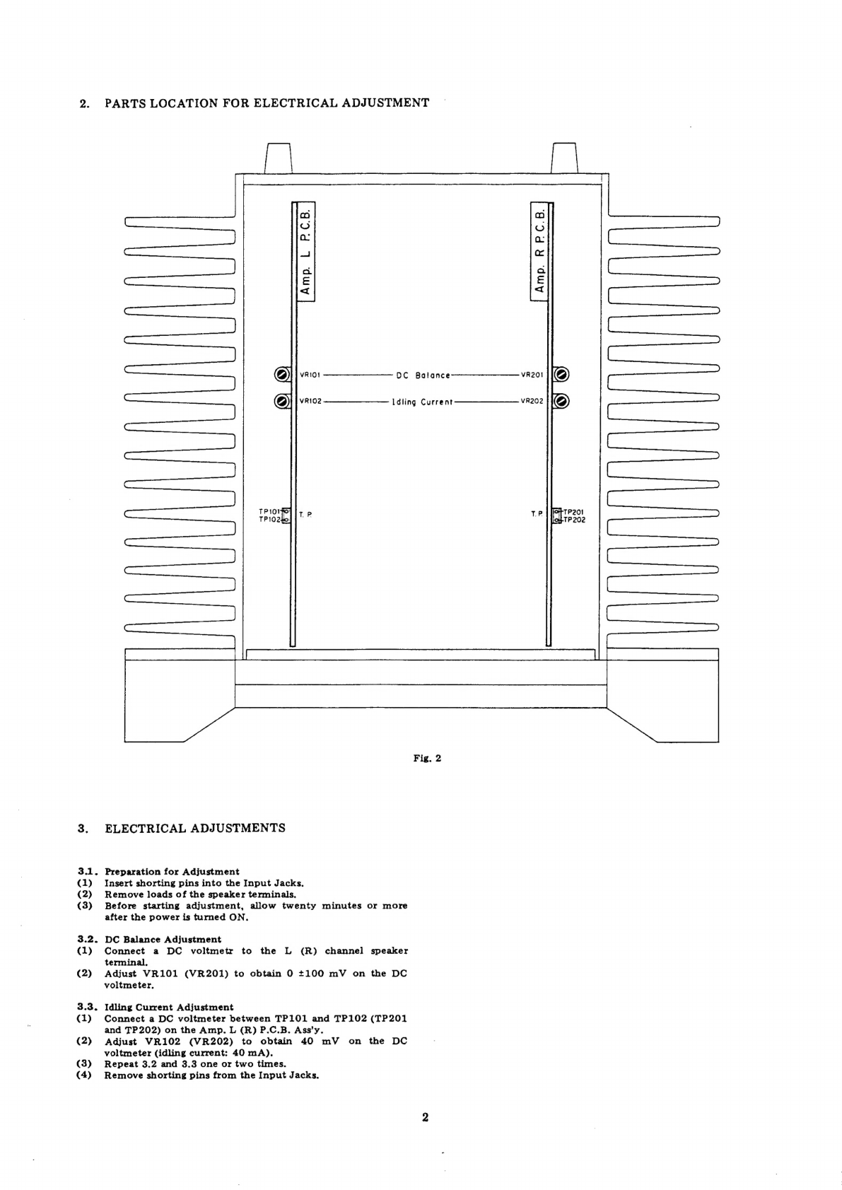
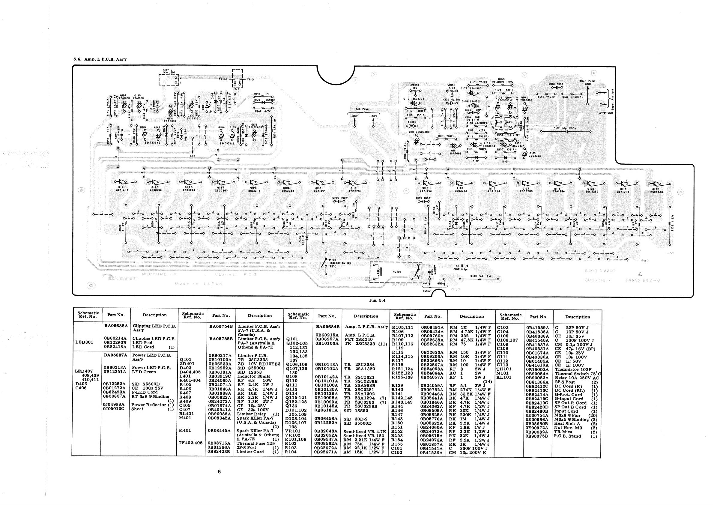
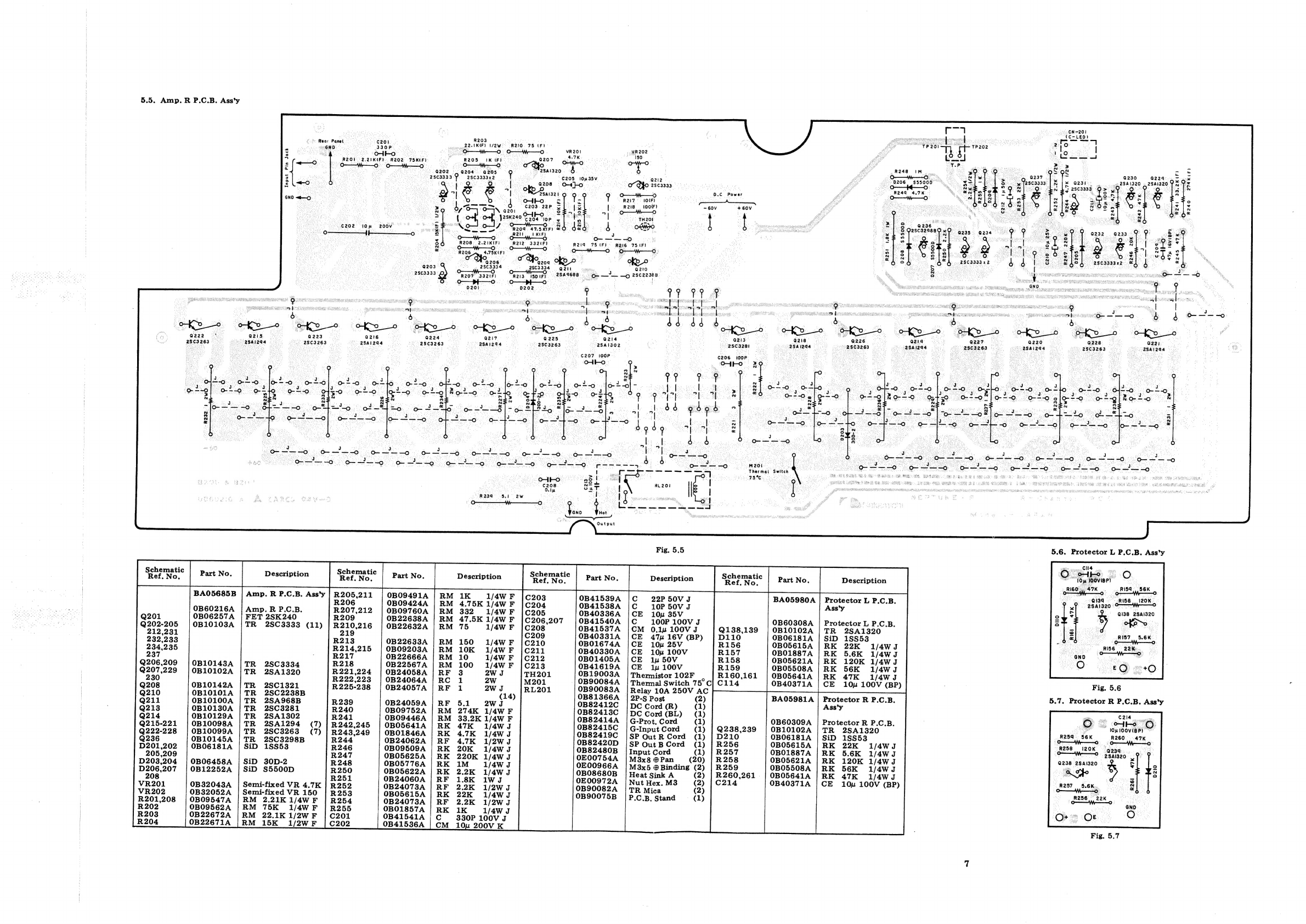
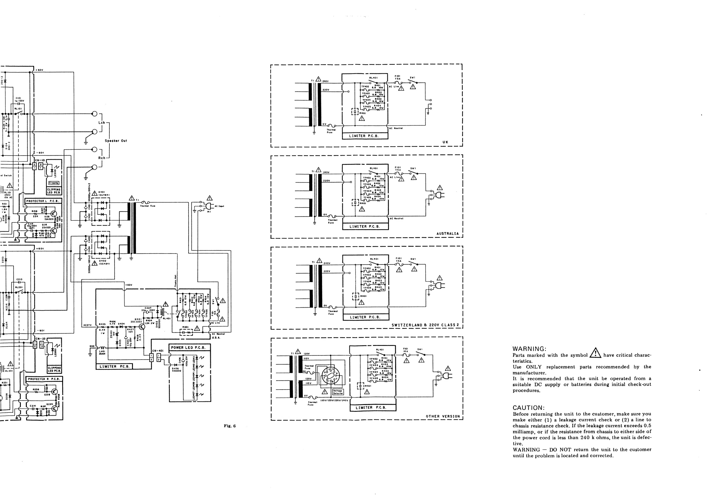
Nakamichi PA-7 User manual
Other Nakamichi Amplifier manuals

Nakamichi
Nakamichi CA-5 User manual

Nakamichi
Nakamichi NDST500A User manual

Nakamichi
Nakamichi IA-2 User manual

Nakamichi
Nakamichi PA-7 User manual

Nakamichi
Nakamichi AVP1 User manual

Nakamichi
Nakamichi NKTA75.2 User manual

Nakamichi
Nakamichi PA-7II User manual

Nakamichi
Nakamichi 610 User manual

Nakamichi
Nakamichi ta-4 User manual

Nakamichi
Nakamichi PA-7 User manual

Nakamichi
Nakamichi NGXA80.4 User manual

Nakamichi
Nakamichi 420 User manual

Nakamichi
Nakamichi PA-5 User manual

Nakamichi
Nakamichi 620 User manual

Nakamichi
Nakamichi NGXA80.6 User manual

Nakamichi
Nakamichi CA-5 User manual

Nakamichi
Nakamichi 620 User manual

Nakamichi
Nakamichi NGTD1 User manual

Nakamichi
Nakamichi 620 User manual

Nakamichi
Nakamichi CA-5AII User manual