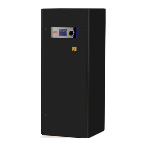
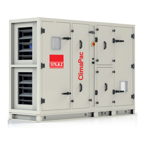
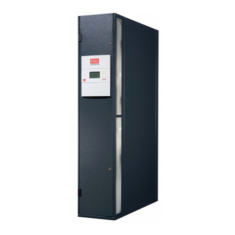
Stulz CyberHandler 2 User manual

Air Handling Unit
Installation, Operation and Maintenance manual
CyberHandler 2

2EN/05.2019 © STULZ GmbH – all rights reserved
CYBERHANDLER 2 INSTALLATION, OPERATION AND MAINTENANCE MANUAL
Contents
1 Information on this manual . . . . . . . . . . . . . . . . . . . . . . . . . . 3
1.1 Safety signs. . . . . . . . . . . . . . . . . . . . . . . . . . . . . . . . . . .3
1.2 components signs . . . . . . . . . . . . . . . . . . . . . . . . . . . . . . . 3
2 Safety . . . . . . . . . . . . . . . . . . . . . . . . . . . . . . . . . . . . . . 4
2.1 Intended use . . . . . . . . . . . . . . . . . . . . . . . . . . . . . . . . . . 4
2.2 Safety Instructions . . . . . . . . . . . . . . . . . . . . . . . . . . . . . . . 4
2.3 Handling refrigerants (units with DX Top-up or DX Redundant) . . . . . . 5
2.4 Safety and environmental requirements . . . . . . . . . . . . . . . . . . . 6
3 Residual risks. . . . . . . . . . . . . . . . . . . . . . . . . . . . . . . . . .7
4 Description . . . . . . . . . . . . . . . . . . . . . . . . . . . . . . . . . . . 9
4.1 Type Code . . . . . . . . . . . . . . . . . . . . . . . . . . . . . . . . . . . 9
4.2 Air Handling Unit design. . . . . . . . . . . . . . . . . . . . . . . . . . . 10
4.3 Operation limits. . . . . . . . . . . . . . . . . . . . . . . . . . . . . . . . 12
4.4 Technical data . . . . . . . . . . . . . . . . . . . . . . . . . . . . . . . . 12
5 Delivery/Transport/Storage. . . . . . . . . . . . . . . . . . . . . . . . . 13
5.1 Delivery of units . . . . . . . . . . . . . . . . . . . . . . . . . . . . . . . 13
5.2 Storage . . . . . . . . . . . . . . . . . . . . . . . . . . . . . . . . . . . . 13
5.3 Transport . . . . . . . . . . . . . . . . . . . . . . . . . . . . . . . . . . . 13
5.3.1 Transport with forklift . . . . . . . . . . . . . . . . . . . . . . . . . 13
5.3.2 Transport with crane (via shackles). . . . . . . . . . . . . . . . . . 14
6 Assembly and Installation . . . . . . . . . . . . . . . . . . . . . . . . . . 15
6.1 Supplied parts . . . . . . . . . . . . . . . . . . . . . . . . . . . . . . . . 15
6.2 Unit placement . . . . . . . . . . . . . . . . . . . . . . . . . . . . . . . . 15
6.3 Assembly (units in several parts) . . . . . . . . . . . . . . . . . . . . . . 18
6.4 Installation . . . . . . . . . . . . . . . . . . . . . . . . . . . . . . . . . . 20
6.4.1 Electrical connection . . . . . . . . . . . . . . . . . . . . . . . . . 20
6.4.2 Adiabatic system. . . . . . . . . . . . . . . . . . . . . . . . . . . . 21
6.4.3 Cooling Coil (version CWT/CWR/DXR). . . . . . . . . . . . . . . . 23
6.4.4 Refrigerant circuit (version DXT/DXR) . . . . . . . . . . . . . . . . 24
7 Commissioning . . . . . . . . . . . . . . . . . . . . . . . . . . . . . . . .29
7.1 Refrigerant circuit . . . . . . . . . . . . . . . . . . . . . . . . . . . . . . 29
7.2 Adiabatic System . . . . . . . . . . . . . . . . . . . . . . . . . . . . . . . 30
7.3 CW coil . . . . . . . . . . . . . . . . . . . . . . . . . . . . . . . . . . . . 31
8 Maintenance . . . . . . . . . . . . . . . . . . . . . . . . . . . . . . . . . 32
8.1 Safety instructions . . . . . . . . . . . . . . . . . . . . . . . . . . . . . . 32
8.2 Periodic maintenance . . . . . . . . . . . . . . . . . . . . . . . . . . . . 32
8.3 Air filters . . . . . . . . . . . . . . . . . . . . . . . . . . . . . . . . . . . 34
8.4 Plate heat exchanger . . . . . . . . . . . . . . . . . . . . . . . . . . . . 34
8.5 Plate-fin heat exchangers (Cooling coil, heating coils) . . . . . . . . . . 34
8.6 EC fans . . . . . . . . . . . . . . . . . . . . . . . . . . . . . . . . . . . . 35
8.7 Adiabatic system . . . . . . . . . . . . . . . . . . . . . . . . . . . . . . . 36
8.8 Refrigerant circuit . . . . . . . . . . . . . . . . . . . . . . . . . . . . . . 37
8.9 Unit housing . . . . . . . . . . . . . . . . . . . . . . . . . . . . . . . . . 40
9 Dismantling and disposal . . . . . . . . . . . . . . . . . . . . . . . . . . 41
10 Contents of the CE declaration of conformity . . . . . . . . . . . . . . . 43

CYBERHANDLER 2 INSTALLATION, OPERATION AND MAINTENANCE MANUAL
EN/05.2019 © STULZ GmbH – all rights reserved 3
1 Information on this manual
Read this documentation prior to assembly and commissioning. This is a requirement for safe
work and trouble free handling.
Observe the safety guidelines and warnings in this documentation and on the product itself.
Ensure this manual is available at the place where the unit is installed for any person who is
likely to work on the unit (e.g. maintenance personnel, building technicians, electricians…).
1.1 Safety signs
threatening danger, serious bodily harm and even death
material damage
threatening danger due to electrical components
threatening danger due to suspended load
hand entanglement hazard
important information and application notice
1.2 Components signs
Fan Empty section
Cooling coil Damper
Cooling/heating coil Filter
Heating coil Silencer
Humidifier Controller
Plate heat exchanger Compressor

4EN/05.2019 © STULZ GmbH – all rights reserved
CYBERHANDLER 2 INSTALLATION, OPERATION AND MAINTENANCE MANUAL
2 Safety
2.1 Intended use
The CyberHandler2 must only be used for ventilation and air conditioning of building.
It includes:
• filtering normally polluted air.
• air cooling.
• air heating.
• air humidifying and/or dehumidifying
Proper use also includes observance of the operation manual and instructions from the manu-
facturer of the individual components, as well as the inspection and maintenance intervals stipu-
lated by Stulz.
Any use other than that described above is considered improper. If necessary, check if your
units are suitable for your intended purpose and application. The manufacturer/supplier is not
liable for any damages arising from improper use. The user alone bears the risk.
Misuse particularly includes:
• Conveying any other gases except air
• Conveying steam or water
• Coarse filtering and/or filtering any other media except air
• Chopping up or reducing size of materials
• Drying out clothing
• The unit is not suitable for handling abrasive media.
The CyberHandler2 unit is intended to be installed in environments with special conditions (for
example: explosive areas, rooms with conductive dust, electromagnetic field or aggressive or
corrosive atmosphere), consult previously STULZ Tecnivel to check the compatibility of the UTA
with these conditions.
The CyberHandler2 unit should not be accessible to the public.
2.2 Safety Instructions
General
These operating instructions contain basic information which is to be complied with for instal-
lation, operation and maintenance. They must therefore be read and complied with by the fitter
and the responsible trained staff/operators before assembly and commissioning. They must be
permanently available at the place where the system is used.
INFORMATION
This unit contains fluorinated greenhouse gas covered by the Kyoto protocol
The AHU are to be properly assembled and used under precise observation of our instructions.
If the assembly is performed contrary to our regulations, and the defect/damage which has
occurred is causally associated with inappropriate modification, processing or any other treat-
ment, all claims to damages compensation or warranty are thereby excluded.

CYBERHANDLER 2 INSTALLATION, OPERATION AND MAINTENANCE MANUAL
EN/05.2019 © STULZ GmbH – all rights reserved 5
2.3 Handling refrigerants (units with DX Top-up or DX Redundant)
According to EN 378, refrigerants are divided in groups in respect of health and safety: R410a
belongs to Group L1.
• Adherence to the regulations by law and guide-lines.
• Execution only by competent staff.
• Responsability for correct disposal of refrigerant and system parts is incumbent on the
operator.
• Refrigerants have a narcotic effect when inhaled in high concentrations.
• The room is to be evacuated immediately if high concentrations of refrigerant suddenly occur.
The room may only be entered again after adequate ventilation.
• If unavoidable work is required in the presence of a high concentration of refrigerant, breath-
ing apparatus must be worn. This does not mean simple filter masks. Comply with breathing
protection data sheet.
• Safety glasses and safety gloves are to be worn.
• Do not eat, drink or smoke at work.
• Liquid refrigerant must not get onto the skin (risk of burns).
• Only use in well ventilated areas.
• Do not inhale refrigerant vapours.
• Warn against intentional misuse.
• It is absolutely essential to comply with the first aid measures if accidents occur.
Only trained and qualified electricians are permitted to undertake work on the
electrical system.
Respect the corresponding EN- and IEC standards for the electrical connection of the
unit and observe the conditions of the power supply companies.
• installation, commissioning, maintenance and operation works have to be carried out by
qualified persons only,
• Observance of the regulations for accident prevention,
• Stay out of danger when lifting and setting off the unit,
• The AHU may only be operated with its revision doors and panels (casing) completely closed
• The air-handling unit must always be operated within the range of operating parameters
stipulated in the technical documentation supplied by STULZ.
• Secure the unit to avoid the risk of overturning
• Safety devices may not be bypassed.
• Prior to all work on the AHU – or opening the revision doors – ensure that:
• power supply is shut off (power off all poles) and safeguarded from unauthorized power-
ing on,
• all moving components - in particular - fan impeller, motor, rotary heat exchanger, control
and shut-off dampers – have come to a standstill: wait at least 5 minutes after deacti-
vating the unit,
• Heat exchangers have cooled down to reach ambient temperature,
• No persons are present in danger areas e.g. inside the unit
• Work performed on the AHU requires personal protective equipment (Personal Protective
Equipment),
• The air handled by the equipment must not contain health-endangering, flammable, explo-
sive, aggressive, corrosive or otherwise hazardous constituents, which would otherwise be
distributed by the ducting system or the building and can have a health-impairing or even
fatal effect on personnel, animals or plants living in the building.

6EN/05.2019 © STULZ GmbH – all rights reserved
CYBERHANDLER 2 INSTALLATION, OPERATION AND MAINTENANCE MANUAL
• Refrigerants containing FCs contribute to the global warming and with this to climate changes.
The FCs must therefore be disposed of in accordance with the regulations, i.e. only by compa-
nies specially qualified and licensed as recognized disposal companies for refrigerants.
2.4 Safety and environmental requirements
The following requirements relate to the operation of refrigerating plants within the European
Community.
• The used components must correspond to the pressure equipment guide-line EC/97/23 and
EN378 part 1-4.
• Independent of the design, the equipment and inspection before the delivery, also the opera-
tor of such plants has duties according to EN 378 and national regulations.
This concerns the installation, the operation and the repeated inspection:
• Installation: according to EN 378.
• Operation: Determination of emergency measures (accidents, malfunctions)
Creation of an abbreviated instruction and notification (template page)
a. A unit protocol must be kept.
b. To be stored in the proximity of the unit
c. Access for competent staff in case of repairs and repeated inspection must be
ensured.
• Repeated inspection: according to EN 378.
The operator is responsible for the execution.
The operator must ensure that all maintenance, inspection and assembly work is carried out
by authorized and qualified specialist staff who have made an in-depth study of the operating
instructions.
It is absolutely essential to comply with the procedure for shutting down the system described
in the operating instructions. Before maintenance work, the unit must be switched off at the
main switch and a warning sign displayed to prevent unintentional switching-on.
Independent conversion and manufacture of replacement parts
The system may only be converted or modified after consultation with STULZ. Original replace-
ment parts and replacement parts/accessories authorized by STULZ are an aid to safety.
First aid measures
• If health problems occur during or after handling fluorinated hydrocarbons, a doctor is to be
consulted immediately. The doctor is to be informed that the work involved the use of fluori-
nated hydrocarbons.
• In the case of acute effects, the casualty is to be brought into the fresh air as quickly as
possible.
• Splashes of fluorinated hydrocarbons in the eyes can be blown out or fanned out by an assis-
tant. Then rinse with water.
Unacceptable operating methods
The operating safety of the system is only guaranteed when it is used as intended. The limit
values stipulated in the technical data must not be exceeded under any circumstances.

CYBERHANDLER 2 INSTALLATION, OPERATION AND MAINTENANCE MANUAL
EN/05.2019 © STULZ GmbH – all rights reserved 7
Area Cause Danger Safety note
Refrigerant piping Leaks in the refrigerant
piping, defective safety
valve/high pressure
switch, fire
Discharge of refrigerant under high
pressure, explosion of pipe sections,
formation of acid vapours with open
flames
In case of fire wear protective mask.
Hot gas line The line can take a
temperature of up to
70°C.
Burns in case of contact to the skin Wear safety gloves. Cover lower arms
with clothing.
Electrical alimentation Falsely dimensioned
cables or protection
devices
Short-circuit, fire, acid vapours Correctly design alimentation cables
and protection elements. Wear protec-
tive mask.
Operation
Area Cause Danger Safety note
Water piping Leaks in the water lines,
closed stop valves
Discharge of water under high pres-
sure, contact with the skin of ethylen
glycol, irritation of eyes and respiratory
system by glycol vapours, increased
risk of electric shock in combination
with electricity, risk of slipping
Open stop valves.
Wear rubber gloves, ethylen glycol is
absorbed by the skin. Avoid swallowing
water with glycol additives.
Electrical box Short circuit Electric arc, acid vapours Retighten terminal connections, Wear
protective gloves
Start-up
Area Cause Danger Safety note
Under the unit Defective lifting device Bruising Keep away from under the unit
Beside the unit Uneven or insufficient
foundation
Bruising by tipping over of the unit Make sure, the foundation is even and
stable. Wear protective equipment
(helmet, gloves, safety shoes).
In the lower part of
the unit
sharp edges, built-in
parts
Cuts, concussion damage Wear safety glasses and gloves.
Electrical box Connection cable under
voltage, sharp edges
of the openings for the
cable introduction
Electric shock, cable damage at
positioning
Check and make sure the unit is
deenergized. Stand on isolated ground.
Take care that sharp edges are always
protected by rubber grommets
Transport, Installation
3 Residual risks

8EN/05.2019 © STULZ GmbH – all rights reserved
CYBERHANDLER 2 INSTALLATION, OPERATION AND MAINTENANCE MANUAL
Area Cause Danger Safety note
Refrigerant piping Soldering off or cutting
the refrigerant pipes
still under pressure.
Discharge of refrigerant under high
pressure, burns in case of contact to
the skin.
Depressurize pipes before disconnect-
ing them.
Wear safety glasses and gloves.
Water piping Unscrewing the water
pipes still under
pressure.
Discharge of water under high pres-
sure, contact with the skin of ethylen
glycol, increased risk of electric shock
in combination with electricity, risk of
slipping
Drain of cooling water by drain valve.
Wear rubber gloves.
Electrical box Live electrical alimenta-
tion cable
Electric shock Check de-energized state of the
alimentation before dismantling, Wear
safety gloves.
Dismantling
Area Cause Danger Safety note
Refrigerant piping Leaks in the refrigerant
piping, defective safety
valve/high pressure
switch.
Discharge of refrigerant under high
pressure, burns in case of contact to
the skin, formation of acid vapours with
open flames
Wear safety glasses and gloves.
Pressure lines,
compressor
Heat Burns in case of contact to the skin Wear safety gloves. Avoid contact to
hot unit parts.
Fin heat ex- changer,
air side
Sharp edges, fins Injuries by cutting Wear safety gloves.
Electrical box Live components,
supposed to be
voltage-free.
Electric shock 1. Disconnect mains.
2. Prevent reconnection.
3. Test for absence of harmful voltages.
4. Ground and short circuit L1-, L2- and
L3 conductor in electric cabinet.
5. Cover or close off nearby live
components.
To energize apply these procedures in
reverse order.
Maintenance

CYBERHANDLER 2 INSTALLATION, OPERATION AND MAINTENANCE MANUAL
EN/05.2019 © STULZ GmbH – all rights reserved 9
4 Description
4.1 Type Code
The type code represents the unit variant of your air handling unit and can be found on the type
plate.
CH2 -S1 - ADB - SH/RH
Product range
CyberHandler2
Size
From S1 to S9
Cooling Configuration
ADB: Adiabatic only
CWT: Chilled Water Top-Up Coil
CWR: Chilled Water Redundant Coil
DXT: DX Top-Up integrated system
DXR: DX Redundant system with outdoor condensing unit
Installation Configurations
SH/RH: Supply Horizontal/Return Horizontal (Wall)
SB/RH: Supply Bottom/Return Horizontal (Roof)
SB/RB: Supply Bottom/Return Bottom (Roof)
STULZ TECNIVEL SL
C/ Carabaña S/N -
28925 - Alcorcón
-Madrid - SPAIN
Tel: +34 915 571 130
E-mail: info@stulztecnivel.com
Product
Model
Seria No.
Supply voltage
Cooling capacity
Refrigerant
Max. operation pressure
Made in Spain
Year of manufacture
Weight
Max. Current
Contains fluorinated greenhouse
gases
Air Handling Unit
CH2-S1-ADB-SH/RH
CL-000-18
400 V ± 10 %
50 Hz ± 1 %
2018
276 A
252 Kw
R410A
40 Kg
83,5 T
42
bar
25
bar
BP
HP
CO2eq
Charge
Type
5325 Kg

10 EN/05.2019 © STULZ GmbH – all rights reserved
CYBERHANDLER 2 INSTALLATION, OPERATION AND MAINTENANCE MANUAL
Customer-specified, non-standard features or design variations may not be described
in this manual. Refer to the installation and/or electrical drawings supplied with your
unit for details on additional feature(s). In some cases, an addendum to this manual
may be provided to further describe the feature(s).
4.2 Air Handling Unit design
General design:
1. Outdoor damper
Frame and blades are made of aluminium.
2. Filters, outdoor side
Bag filters are used ensure a pressure loss as low as possible.
3. Double Air-to-Air plate heat exchanger
The casing is made of galvanized steel with epoxy coating and the fins are made of aluminium with
a special coating making it more resistant to aggressive water.
4. Adiabatic system
4a: Water pump: centrifugal type.
4b: Spray Nozzles: full water cone type, made of stainless steel.
5. Compressors
Compressors used in Cyberhandler 2 units with DX system (DX Top-up and DX Redundant) are
scroll compressors.
These units are equipped with one inverter compressor and depending on the required cooling
capacity, one or 2 ON/OFF compressors can be added.
6. Cooling coil
The cooling coil can be either a direct expansion coil (DXT and DXR configurations) or a chilled
water coil (CWT/CWR configuration). For the units with ADB configuration, there is no cooling coil
installed inside the unit.
OA: Outdoor Air SA: Supply Air
EA: Exhaust Air RA: Return Air
Fig 4.1: View of a CH2-DXT-SH/RH
Climatizadores · Condensadores · Aero-refrigeradores · Fan Coils ·Baterias
Air Handlers · Condensers · Dry-Coolers · Air-heaters · Coils
4.2 Air Handling Unit design
New text to insert in the IOM manual (replacing the current text, p.10-12):
Customer-specified, non-standard features or design variations may not be
described in this manual. Refer to the installation and/or electrical drawings
supplied with your unit for details on additional feature(s). In some cases, an
addendum to this manual may be provided to further describe the feature(s).
General design:
Fig 4.1: View of a CH2-DXT-SH/RH
OA: Outdoor Air
SA: Supply Air
EA: Exhaust Air
RA: Return Air
1. Outdoor damper
Frame and blades are made of aluminium.
OA
SA
RA
EA
1
3
2
4a
5
11
12
13
14
15
9
8
7
6
4b
16
10
3

CYBERHANDLER 2 INSTALLATION, OPERATION AND MAINTENANCE MANUAL
EN/05.2019 © STULZ GmbH – all rights reserved 11
7. Cooling coil
The CH2 control consists of the C7000 controller and following sensors are mounted as standard:
- Temperature and humidity sensor (outdoor air)
- Temperature and humidity sensor (supply air)
- Temperature and humidity sensor (Return air)
- Pressure switch (Clogged filters alarm, IT room side)
For models equipped with a refrigerant circuit (DXT/DXR), additional sensors are used for refrigerant
circuit control.
For more information about the controller, see the C7000 user’s manual.
8. Electrical cabinet
The electric cabinet is housed inside the unit and is made according to the EN60204-1 IEC
standard.
9. Supply damper
Frame and blades are made of aluminium.
10. Return damper
Frame and blades are made of aluminium.
11. Filters, IT room side
Bag filters are used ensure a pressure loss as low as possible.
12. Supply fans
Supply fans are Electronically Commutated type and mounted in fan wall arrangement.
13. Exhaust fans
Exhaust fans are Electronically Commutated type and mounted in fan wall arrangement.
14. Recirculation damper
Frame and blades are made of aluminium.
15. Condenser coil
Only the model with DX top-up cooling is equipped with a condenser coil.
16. Exhaust damper
Frame and blades are made of aluminium.
Operation
In every unit there is a double plate heat exchanger with an adiabatic cooling system. The noz-
zles spray water directly on the lower plate heat exchanger to ensure the process reaches the
maximum efficiency.
This indirect adiabatic cooling process can be completed by a mechanical cooling system.
This mechanical cooling is provided by either a Chilled water coil (CWT and CWR configurations)
or a DX system (DXT and DXR configurations) with integrated or remote condenser.
The Cyber Handler 2 works in 3 operating modes depending on the outdoor conditions:
• Dry mode: when the outdoor temperature is low enough, the cooling is provided by the plate
heat exchanger only (adiabatic and mechanical cooling OFF),
• Wet mode: when the outdoor temperature is not low enough to allow the plate heat
exchanger to provide the required cooling capacity, the adiabatic system switches on to cool
down the outdoor air.
• Mix mode (not available for units with only adiabatic cooling): when the outdoor temperature
is very high, the mechanical cooling switches on to top-up the indirect adiabatic cooling.

12 EN/05.2019 © STULZ GmbH – all rights reserved
CYBERHANDLER 2 INSTALLATION, OPERATION AND MAINTENANCE MANUAL
The C7000 controller handles the changes between the different operating modes (see C7000
manual)
4.3 Operation limits
• Outdoor ambient conditions:
Lower limit Upper limit
Temperature -15º C 50ºC
• Return air conditions
Lower limit Upper limit
Temperature 30ºC 45ºC
Humidity -60% r.h.
• Storage conditions
Lower limit Upper limit
Temperature -10ºC 50ºC
Humidity Dry, non-condensing atmosphere
• Supply voltage:
Voltage: 380 - 415V / 3ph / 50Hz; N; PE
Voltage tolerance: ± 10%
Frequency tolerance: ± 1%
4.4 Technical data
Refer to the order-related documentation for the specific configuration of your CyberHandler 2
unit (unit drawing, electrical diagram, refrigerant circuit diagram, technical data).

CYBERHANDLER 2 INSTALLATION, OPERATION AND MAINTENANCE MANUAL
EN/05.2019 © STULZ GmbH – all rights reserved 13
Service doors must always be closed during transport
When delivery is accepted, the unit is to be checked against the delivery note for
completeness and checked for external damage which is to be recorded on the con-
signment note in the presence of the freight forwarder.
• You receive the consignment papers with the delivery of the AHU.
• The shipment is made ex works, in case of shipment damages, please assert your
claim directly towards the carrier.
5 Delivery/Transport/Storage
5.1 Delivery of units
5.2 Storage
5.3 Transport
The CyberHandler 2 unit is delivered either completely assembled or in separated unit compo-
nents divided as indicated in the unit drawing.
The complete units and individual modules must always be transported upright.
If you put the unit into intermediate storage before the installation, the following measures have
to be carried out to protect the unit from damage and corrosion:
• Make sure that the water connections are provided with protective hoods. If the intermediate
storage exceeds 2 months, we recommend filling the pipes with nitrogen.
• the temperature at the storage point should be within the range -10ºC to 50°C, and the site
should be dry and not exposed to direct sunlight.
• the unit should be stored packaged to avoid the risk of corrosion especially of the heat
exchanger fins.
5.3.1 Transport with forklift
When transporting the unit with a forklift truck, make sure that only the base frame or supplied
pallet rest on the forks and not the unit base.

14 EN/05.2019 © STULZ GmbH – all rights reserved
CYBERHANDLER 2 INSTALLATION, OPERATION AND MAINTENANCE MANUAL
Due to the risk of scratching the panels, we advise not to use chains.
Don’t remove the package until the unit is in its final position
All the local standards and regulations about crane transport must be observed.
Never stand beneath suspended loads, since there is always a risk that the lifting
gear, shackles, ropes or slings are faulty or damaged
5.3.2 Transport with crane (via shackles)
The CyberHandler2 unit has several hoisting plates on the baseframe where shackles must be
mounted for craning.
Fig. 5-1: Lifting gear
In order to ensure a safe craning of the units, instructions here below must be followed:
• Mount the shackles on the lifting lugs on the base frame.
• Use crossbeams with the appropriate width to prevent the sling to rub against the unit.
• With weatherproof units, make sure the protruding parts of the roof are not damaged by the
liftinggear.
• Do not lift any other loads together with the shipment unit.
• Ensure the suspension angle doesn’t exceed 60°.
Detail of the
attachment system
Crossbeams

CYBERHANDLER 2 INSTALLATION, OPERATION AND MAINTENANCE MANUAL
EN/05.2019 © STULZ GmbH – all rights reserved 15
6 Assembly and Installation
6.1 Supplied parts
6.2 Unit placement
• M8 30 mm socket cap screws with (for fixing element).
• M8 30 mm Hex-head cap screws (for base assembly).
• M8 nuts (for module assembly).
• M8 / 125 40 mm (units with refrigerant circuit for refrigerant pipes assembly)
• The base on which the unit is to be installed must be level, flat and of adequate load-bearing
capacity.
• The minimum height of the base must correspond to the siphon height (for siphon calculation
see 6.4.2).
• In case of using strip foundations, additional cross supports are required at the beginning and
end of the unit, as well as at the joints between unit sections.
• The whole baseframe of the unit must rest on the base and make full surface contact with it.
• Pad or point contact is not permissible.
The fulfillment of these requirements is essential in order to avoid possible problems
with the unit, such as door jamming.
Foundations requirements
Structure-borne sound insulation
In order to insulate the supporting structure from the vibrations produced by the unit, it is rec-
ommended to use suitable anti-vibration mounts, such as rubber strip.
Fig. 6-1: Installation on concrete base Fig. 6-2: Installation on steel beam
Unit’s baseframe
Vibration absorber
Steel beam
Concrete base
Crossbeams, shackles and slings/ropes used in the lifting gear are not supplied by
Stulz
To transport a complete unit or several modules joined together, the lifting gear must
be fixed to all lifting lugs of the baseframe

16 EN/05.2019 © STULZ GmbH – all rights reserved
CYBERHANDLER 2 INSTALLATION, OPERATION AND MAINTENANCE MANUAL
Fig 6-3: Space requirements
Fig 6-4: Installation against the wall
Space requirements for installation, maintenance and operation
The minimum space necessary for installation, operation and maintenance is one unit width on
the operator side (see fig. 6-3).
If the unit is to be installed against a wall (fig. 6-4) or back-to-back with another unit (fig. 6-5),
fixing elements for modules connection must be located inside the unit (on the rear side).
Fig 6-5: Installation back-to-back
OPERATING SIDE
OPERATING SIDE
OPERATING SIDE OPERATING SIDE

CYBERHANDLER 2 INSTALLATION, OPERATION AND MAINTENANCE MANUAL
EN/05.2019 © STULZ GmbH – all rights reserved 17
Duct work must be installed by qualified staff
Warning: weatherproof units are not substitute to roof.
It is not allowed to use weatherproof units as supporting surfaces of a building or
similar roof substitutes in accordance to EN 13053
Fig 6-6: Clearance in the air intake area (1 wall)
Fig 6-7: Clearance in the air intake area (2 walls)
If no ductwork is connected, a clearance must be left in front of the outdoor air intake/exhaust
air, as shown on Fig. 6-6 and Fig. 6-7:
In order to avoid any air by-pass between outdoor air and exhaust air, the appropriate measure
must be taken to conveniently separate outdoor airflow and exhaust airflow (e.g. duct work on
the exhaust side).
OUTDOOR AIR
OUTDOOR AIR

18 EN/05.2019 © STULZ GmbH – all rights reserved
CYBERHANDLER 2 INSTALLATION, OPERATION AND MAINTENANCE MANUAL
Assembly sequence:
Aluminium profiles
• Insert first the M8 nuts in the joining element and then insert the M8 30 mm socket cap
screw in the other part of the fixing element.
• Tighten the screw with the Allen key
• Baseframe:
• Insert first the M8 30 mm Hex-head cap screws in the fixing element of the baseframe and
secure it with the M8 nuts.
Fig 6-8: Assembly of modules
Fig 6-9: Assembly of baseframe
Screws/nuts
Fixing element
Module 1
Module 1
Module 2
Module 2
6.3 Assembly (units in several parts)
Before assembling the modules, check the following points:
• Every module must be placed in its final position according to the unit drawing (Every module
is named after a letter). To ensure a correct tightness between 2 modules, every module is
provided with rubber strip in factory.
• All fixing elements, drilled holes are perfectly placed in order all the modules can be fixed
together.

CYBERHANDLER 2 INSTALLATION, OPERATION AND MAINTENANCE MANUAL
EN/05.2019 © STULZ GmbH – all rights reserved 19
Several modules joined together can be transported together only fixing the lifting
gear to all the lifting lugs of the baseframe.
• Intermediate baseframe:
• The intermediate baseframe (if existing) of the double deck units must be fixed to the alumin-
ium profiles of the lower modules with screws.
• Roof (units for outdoor installation):
• Place a rivet in each drilled hole and secure it with a rivet gun
Fig 6-10: Assembly of intermediate baseframe
Fig. 6-11: Assembly of roof
Rivet
Module 2 Module 1
Lower module
Upper module
Screw
Intermediate
baseframe

20 EN/05.2019 © STULZ GmbH – all rights reserved
CYBERHANDLER 2 INSTALLATION, OPERATION AND MAINTENANCE MANUAL
Make sure that the phase rotation is correct, the rotating field must turn right!
For use of leakage-current (FI) circuit breakers, EN 50178 5.2.11.2 must be taken
into account. Only type B pulse-current FI circuit breakers are permitted. FI circuit
breakers do not provide protection against bodily harm during operation of the unit or
frequency converters.
The power supply system on site and the pre-fuses must be designed for the total
current of the unit (see data sheet of your unit). Make sure that the power supply cor-
responds to the indications on the rating plate and that the tolerances according to the
“Application limits” are not exceeded.
In addition to this, the asymmetry of phase between the conductors may amount to
2% maximally. The asymmetry of phase is determined by measuring the voltage differ-
ence between the phase conductors.
Cable Connect to
Phase 1/2/3 Main switch L1/L2/L3
PE PE Rail
Neutral Neutral terminal (N)
Once connected, the cables must be secured by the pull relief screw.
The electric cable must be connected as following:
Fig 6-7: Power supply cable insertion in the electrical cabinet
Power supply connection
Specifications
Voltage supply: 400 V / 3 Ph / 50 Hz / N / PE / TNS / TNCS
Power supply cable: cable cross section must be chosen according to electrical
data of the unit (available in the technical data sheet on request) and adapted to local
requirements, laying and cable length.
Cable routing and connection:
The electric cable must be introduced into the electrical cabinet from below, passing it
through the hole drilled on the bottom of the unit.
Before working with electrical wires, make sure they are de-energized. The electric
cables are only to be connected by authorized specialist
6.4 Installation
6.4.1 Electrical connection
Opening for power
cable insertion
Table of contents
Other Stulz Air Handler manuals
Popular Air Handler manuals by other brands

AERMEC
AERMEC T 1 Installation and maintenance manual

Mitsubishi Electric
Mitsubishi Electric PVFY-P12 NAMU-E Service manual

AERA
AERA EVO-C series user manual

Flexit
Flexit Spirit K2R User manual and installation instructions

Salda
Salda RIS 200VE EKO Technical data

Daikin
Daikin UATYQ25ABAY1 Operation manual

Nortek
Nortek B6BV Series installation instructions

BLAUBERG Ventilatoren
BLAUBERG Ventilatoren CIVIC EC DB user manual

Unico
Unico V2430 installation manual

Salda
Salda VEKA INT W 3000 EKO Installation instruction

IV Produkt
IV Produkt Envistar Top Installation, operation and maintenance instructions

Flexit
Flexit Nordic S2 user manual