manuals.online logo
Brands
  1. Home
  2. •
  3. Brands
  4. •
  5. Salda
  6. •
  7. Air Handler
  8. •
  9. Salda RIS 200VE EKO Instruction manual

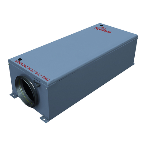
Salda RIS 200VE EKO Instruction manual

Other manuals for RIS 200VE EKO

1

This manual suits for next models

5

Other Salda Air Handler manuals

Salda Smarty 2XV 1.1 Guide

Salda

Salda Smarty 2XV 1.1 Guide

Salda Veka INT 3000-15 L1 EKO User manual

Salda

Salda Veka INT 3000-15 L1 EKO User manual

Salda RIS 5500 HW EKO 3.0 Operator's manual

Salda

Salda RIS 5500 HW EKO 3.0 Operator's manual

Salda VKS 400-200-4 L1 Guide

Salda

Salda VKS 400-200-4 L1 Guide

Salda RIRS 3500VE EKO 3.0 RHX 3X230 User manual

Salda

Salda RIRS 3500VE EKO 3.0 RHX 3X230 User manual

Salda VEKA INT W EKO User manual

Salda

Salda VEKA INT W EKO User manual

Salda Smarty 2R VE User manual

Salda

Salda Smarty 2R VE User manual

Salda SMARTY XP Guide

Salda

Salda SMARTY XP Guide

Salda RIS 700 V EKO 3.0 Guide

Salda

Salda RIS 700 V EKO 3.0 Guide

Salda Veka INT E EKO User manual

Salda

Salda Veka INT E EKO User manual

Salda RIS V EKO 3.0 1200VEL Guide

Salda

Salda RIS V EKO 3.0 1200VEL Guide

Salda Helios KWL-SPV 1900 User manual

Salda

Salda Helios KWL-SPV 1900 User manual

Salda RIS 700 HEL EKO 3.0 Operator's manual

Salda

Salda RIS 700 HEL EKO 3.0 Operator's manual

Salda RIRS 350PE EKO 3.0 User manual

Salda

Salda RIRS 350PE EKO 3.0 User manual

Salda RIS 1900 VEL EKO 3.0 Operator's manual

Salda

Salda RIS 1900 VEL EKO 3.0 Operator's manual

Salda AMBERAIR COMPACT S-CX H Instruction Manual

Salda

Salda AMBERAIR COMPACT S-CX H Instruction Manual

Salda SMARTY XV Series Guide

Salda

Salda SMARTY XV Series Guide

Salda RIRS EKO 3.0 400 VEL Guide

Salda

Salda RIRS EKO 3.0 400 VEL Guide

Salda RIRS 2500VW EKO 3.0 User manual

Salda

Salda RIRS 2500VW EKO 3.0 User manual

Salda RIRS 1900VE EKO 3.0 User manual

Salda

Salda RIRS 1900VE EKO 3.0 User manual

Salda RIS 260VE Instruction manual

Salda

Salda RIS 260VE Instruction manual

Salda RIRS 5500VE/VW EKO 3.0 User manual

Salda

Salda RIRS 5500VE/VW EKO 3.0 User manual

Salda RIRS 400VE EKO 3.0 User manual

Salda

Salda RIRS 400VE EKO 3.0 User manual

Salda RIS 260VW Instruction manual

Salda

Salda RIS 260VW Instruction manual

Popular Air Handler manuals by other brands

Vents VUT 270 V5B EC A14 user manual

Vents

Vents VUT 270 V5B EC A14 user manual

Armstrong Air BCE7S Series installation instructions

Armstrong Air

Armstrong Air BCE7S Series installation instructions

Klimor EVO-S Operation and maintenance manual

Klimor

Klimor EVO-S Operation and maintenance manual

BLAUBERG KOMFORT Roto EC S400 user manual

BLAUBERG

BLAUBERG KOMFORT Roto EC S400 user manual

Trenton TPLP Series installation instructions

Trenton

Trenton TPLP Series installation instructions

Daikin DV PTC 14 Series installation instructions

Daikin

Daikin DV PTC 14 Series installation instructions

Haier HB2400VA1M20 Installation & operation manual

Haier

Haier HB2400VA1M20 Installation & operation manual

Webasto BlueCool A-Series operating instructions

Webasto

Webasto BlueCool A-Series operating instructions

RDZ DA 701 Technical installation manual

RDZ

RDZ DA 701 Technical installation manual

Carrier 39T Installation, Start-Up and Service Instructions

Carrier

Carrier 39T Installation, Start-Up and Service Instructions

Armstrong Air BCE5V Series installation instructions

Armstrong Air

Armstrong Air BCE5V Series installation instructions

Carrier 40MBDAQ Service manual

Carrier

Carrier 40MBDAQ Service manual

TemperZone Econex Pro OPA 1410RLTM4FPQD Installation & maintenance

TemperZone

TemperZone Econex Pro OPA 1410RLTM4FPQD Installation & maintenance

RDZ WHR 200 Technical installation manual

RDZ

RDZ WHR 200 Technical installation manual

AAON H3 Series Installation operation & maintenance

AAON

AAON H3 Series Installation operation & maintenance

Lennox VEOA042N432U Installation & operation instructions

Lennox

Lennox VEOA042N432U Installation & operation instructions

Kemper CleanAirTower operating manual

Kemper

Kemper CleanAirTower operating manual

Lennox SL280DFNV Series installation instructions

Lennox

Lennox SL280DFNV Series installation instructions

manuals.online logo
manuals.online logoBrands
  • About & Mission
  • Contact us
  • Privacy Policy
  • Terms and Conditions

Copyright 2025 Manuals.Online. All Rights Reserved.

Il produttore si riserva il diritto di apportare modiche ai dati tecnici
del prodotto senza preavviso
Subject to technical modication
Änderungen in Konstruktion und Design sind vorbehalten
Производитель оставляет за собой право усовершенствования
технических данных
CENTRALE DI VENTILAZIONE CON RECUPERO DI CALORE
ВЕНТИЛЯЦИОННЫЕ АГРЕГАТЫ С РЕКУПЕРАЦИЕЙ ТЕПЛА
AHU WITH HEAT RECOVERY
LÜFTUNGSGERÄTE MIT WÄRMERÜCKGEWINNUNG
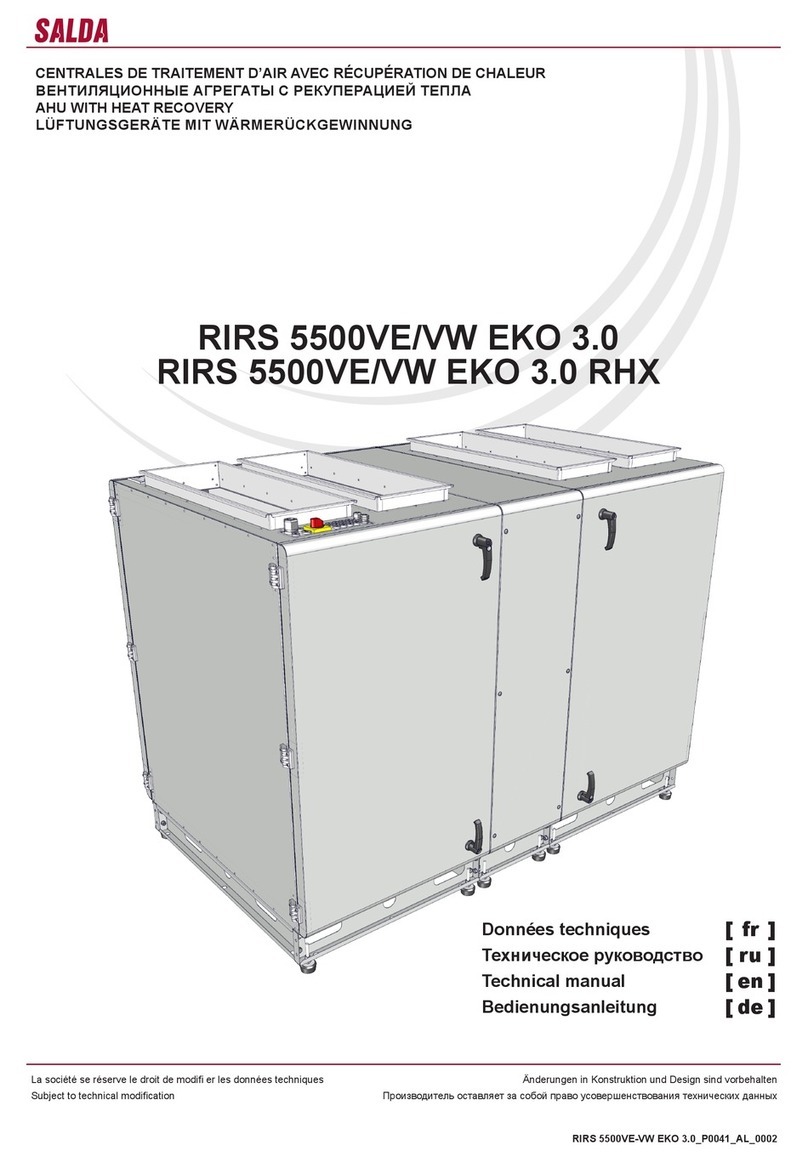
RIS 200VE/VW EKO 3.0
RIS 400VE/VW EKO 3.0
RIS 700VE/VW EKO 3.0
Manuale di uso e mnutenzione [ it ]
Технические данные [ ru ]
Technical data [ en ]
Technische Daten [ de ]
2
RIS VE/VW EKO 3.0
www.salda.lt
[ it ] [ ru ]
Indice
Trasporto e stoccaggio 4
Descrizione 4
Misure di sicurezza 4
Componenti 5
Condizioni d’impiego 5
Manutenzione 6
Filtri 6
Ventilatore 6
Scambiatore di calore 6
Batteria elettrica 7
Garanzia 7
Dati tecnici 8
Filtri 9
Dimensioni 9
Montaggio 11
Scarico condensa 12
Schema dei componenti 14
Versioni delle unità 14
Accessori 15
Collegamenti delle batterie ad acqua AVA/AVS 16
Controllo automatico 16
Protezione del sistema 18
Uso dell‘unità un una rete BMS 19
Indirizzi ModBus 20
Connessione elettrica dell‘unità 21
Guida per la riparazione del sistema 22
Guasti principali dell’unità e soluzioni per eliminarli 25
Scheda di controllo 28
Signicato dei LED 29
Designazione convenzionale, caratteristiche del controllore e dei gruppi
del sistema 29
Controllo periodico dell’unità 32
Schema elettrico 33
Note 39
Tabella di manutenzione del prodotto 40
Содержание
Транспортировка и хранение 4
Описание 4
Меры предосторожности 4
Компоненты 5
Условия работы 5
Обслуживание 6
Фильтры 6
Вентилятор 6
Теплообменник 6
Электрический нагреватель 7
Гарантия 7
Технические данные 8
Фильтры 9
Размеры 9
Установка 11
Дренаж 12
Cхема комплектующих 14
Версии устройств 14
Принадлежности 15
Варианты подключения AVA/AVS 16
Автоматика управления 16
Защита системы 18
Использование агрегата в сети BMS 19
Адреса ModBus 20
Электрическое подключение агрегата ОВК 21
Рекомендации по наладке системы 22
Основные неисправности агрегата ОВК и способы их устранения 25
Пульт управления RG1 28
LED индикации контроллера 29
Условные обозначения, параметры узлов и системы 29
Периодическая проверка системы 32
Схема електрическое подключение 33
Для заметок 39
Таблица обслуживание продукта 40
3
RIS VE/VW EKO 3.0
www.salda.lt
[ en ] [ de ]
Contents
Transportation and storage 4
Description 4
Safety precautions 4
Components 5
Operating conditions 5
Maintenance 6
Filters 6
Fan 6
Heat exchanger 6
Electrical heater 7
Warranty 7
Technical data 8
Filters 9
Dimensions 9
Mounting 11
Draining 12
Scheme for components 14
Unit versions 14
Accessories 15
AVA/AVS connecting options 16
Automatic control 16
System protection 18
Using the unit in BMS network 19
ModBus adresses 20
Electrical connection of the HVAC 21
System adjustment guidelines 22
Basic failures of the HVAC unit and troubleshooting 25
Control board RG1 28
LED indications of the controller 29
Labeling, characteristics of the controller and the system components 29
Regular system check-up 32
Electrical connection diagram 33
Notes 39
Product maintenance table 40
Inhait
Transport und Lagerung 4
Beschreibung 4
Schutzmassnahmen 4
Bestandeile des Gerätes 5
Betriebsbedingungen 5
Bedienung 6
Filter 6
Ventilator 6
Wärmetauscher 6
Elektroheizung 7
Garantie 7
Technische Daten 8
Filter 9
Abmessungen 9
Montage 11
Kondensatablauf 12
Aufbauschema mit bestandteilen des Gerätes 14
Aufbau der Anlage 14
Zubehöre 15
Montage-Varianten vom AVA/AVS 16
Automatische Steuerung 16
Systemschutz 18
Verwendung des Gerätes im BMS-Netz 19
ModBus-Adressen 20
Elektrischer Anschluss der Heizung-, Lüftung- und Klimaeinrichtung 21
Empfehlungen für die Abstimmung des Systems 22
Hauptstörungen der Heizung-, Lüftung- und Klimaeinrichtung sowie Meth-
oden ihrer Beseitigung 25
Steuerplatine RG1 28
LED-Indikationen des Kontrollers 29
Übereinstimmende Kennzeichnungen, Parameter des Kontrollers sowie
der System-Baueinheiten 29
Regelmäßige Systemkontrolle 32
Elektrische Erwärmungseinrichtung 33
Notizen 39
Wartungstabelle des Produktes 40
4
RIS VE/VW EKO 3.0
www.salda.lt
I recuperatori di calore sono unità di ventilazi-
one per il ricambio e la ltrazione dell’aria. Me-
diante lo scambiatore di calore l’energia termi-
ca contenuta nell’aria espulsa viene recuperata
e ceduta all’aria immessa. Sono costituiti da:
• Scambiatore di calore a piastre con rendi-
mento termico no al 90%.
• By-pass automatico con valvola motorizzata
integrata.
• Batteria elettrica integrata, tipo di comando:
0-10V (solo RIS 700VE EKO 3.0).
• Ventilatori EC ad alta efcienza e silenziosità.
• Basso assorbimento elettrico: SFP (Specic
Fan Power) calcolato secondo EN13779
• Interruttore di sicurezza integrato EN 60204-
1:2006.
• 30 mm di isolamento acustico e termico
dell’involucro.
• Controllo automatico integrato, connessione
„Plug and Play“.
• piani M5/M5.
• Il dispositivo non è predisposto per l’uso
all’aria aperta
• Il dispositivo è dotato di sensori della tem-
peratura sull’aria immessa e sull’aria esterna.
• La versione standard prevede la logica di
controllo di tipo ECO.
• In opzione può essere previsto una logica di
controllo SIEMENS o Regin.
Non adatto all’uso all’interno di piscine,
nelle saune e in aitri ambienti simili.
Recuperatore di calore non può essere uti-
lizzato come un riscaldatore dell’aria.
La fornitura standard include (senza accessori
opzionali):
1) sifone – 2 pezzi;
2) maniglia avvitabile, chiudibile a chiave – 1
pezzo;
3) maniglia avvitabile – 1 pezzo.
• L’imballo di tutte le unità garantisce l’integrità
del prodotto in condizioni normali di trasporto.
• Dopo aver tolto l’unità dall’imballaggio, con-
trollare che non sia stata danneggiata du-
rante il transporto. È assolutamente vietato
montare unità danneggiate!!!
• L’imballaggio è solo un mezzo di protezione!
• Caricando e scaricando le unità, usare mezzi
di sollevamento appropriati per evitare danni
e lesioni. Non sollevare mai le unità per i cavi
di alimentazione, per le scatole di connessio-
ne, ange di aspirazione o di scarico. Evitare
urti o forti sollecitazioni al corpo dell’unità.
• Conservare le unità in un locale asciutto in
cui l’umidità relativa non deve superare il
70% (a una temperatura di +20°C), e la tem-
peratura media deve essere mantenuta tra
i +5°C e +30°C. Immagazzinare le unità in
luoghi asciutti ed al riparo dall’acqua e dallo
sporco.
• • Le unità devono essere movimentate me-
diante un carrello elevatore.
• • È sconsigliato lo stoccaggio per un periodo
superiore ad un anno. In caso di stoccaggio
per un periodo superiore ad un anno, prima
del montaggio controllare se i cuscinetti dei
ventilatori e dei motori girano liberamente (far
girare la ventola con una mano), vericare
l’integrità del isolamento del circuito elettrico,
controllare che non vi siano segni di umidità.
• Все оборудование упаковано так, чтобы вы-
держало нормальные условия перевозки.
• После распаковки убедитесь в отсутствии по-
вреждений при транспортировке. Установка
поврежденных устройств запрещена!
• Упаковка является только средством защиты!
• С целью избегания убытков и травм при раз-
грузке и складировании устройств пользуйтесь
соответствующим подъемным оборудовани-
ем. Не поднимайте устройства за кабели пи-
тания, коробки подключения, фланцы забора
или удаления воздуха. Избегайте сотрясений
и ударных перегрузок. Устройства храните в
сухом помещении, где относительная влаж-
ность воздуха не превышает 70 проц. (при
+20ºС), а средняя температура окружающей
среды составляет от +5ºC до +30ºС. Место
складирования должно быть защищено от
грязи и воды.
• Устройства на место их складирования или
установки доставляются подъемниками.
• Не советуется складировать устройства доль-
ше одного года. При более длительном хране-
нии перед установкой необходимо убедиться
в легкости хода подшипников вентиляторов и
двигателей (повернуть крыльчатку рукой), в от-
сутствии повреждений изоляции электроцепи
и конденсации влаги.
• All units are packed in the factory to with-
stand regular conditions of transportation.
• Upon unpacking, check the unit for any dam-
ages caused during transportation. It is for-
bidden to install damaged units!!!
• The package is only for protection purpose!
• While unloading and storing the units, use
suitable lifting equipment to avoid damages
and injuries. Do not lift units by holding on
power supply cables, connection boxes, air
intake or discharge anges. Avoid hits and
shock overloads. Before installation units
must be stored in a dry room with the relative
air humidity not exceeding 70% (at +20°C)
and with the average ambient temperature
ranging between +5°C and +30°C. The place
of storage must be protected against dirt and
water.
• The units must be transported to the storage
or installation site using forklifts.
• The storage is not recommended for a pe-
riod longer than one year. In case of storage
longer than one year, before the installation it
is necessary to verify whether the bearings of
fans and motor rotate easily (turn the impeller
by hand) and if the electric circuit insulation is
not damaged or the moisture is accumulated.
• Alle Geräte sind werksseitig so verpackt,
dass sie den normalen Transportbedingungen
standhaiten können.
• Nach Auspacken des Gerätes überprüfen Sie,
ob es beim Transport nicht beschädigt wurde.
Beschädigte Geräte dürfen nicht montiert wer-
den!!!
• Die Verpackung ist nur eine Schutzmaßnahme!
• Beim Ausladen und Lagern der Geräte verwen-
den Sie geeignete Hebezeuge, um Schäden
und Verletzungen zu vermeiden. Heben Sie die
Geräte nicht an Netzkabeln, Anschlusskästen,
Zu- und Abluftstutzen. Vermeiden Sie Stöße
und Schläge. Lagern Sie die Geräte in einem
trockenen Raum, wo die relative Luftfeuch-
te höchstens 70% (bei +20°C) beträgt und
die durchschnittliche Umgebungstemperatur
zwischen +5°C und +30°C liegt. Der Lagerort
muss vor Schmutz und Wasser geschützt sein.
• An den Lager- bzw. Montageort werden die
Geräte mit Hebezeugen transportiert.
• Eine Lagerung länger als ein Jahr ist nicht
empfehlenswert. Bei einer Lagerung länger
als ein Jahr ist vor der Montage unbedingt zu
prüfen, ob die Ventilator- und Motorlager leicht-
gängig sind (Flügelrad mit der Hand drehen),
ob die Isolierung des elektrischen Stromkreises
nicht beschädigt ist und sich keine Feuchtigkeit
angesammeit hat.
- Non usare questo dispositivo per scopi diversi
da quelli previsti.
- Non manomettere e non modicare il dispositivo.
Ciò può provocare guasti meccanici o funzionali.
- Effettuare il montaggio e i lavori di manutenzione
indossando abbigliamento e protezioni adeguate.
Prestare attenzione: spigoli del dispositivo e
dei suoi componenti possono essere taglienti
e appuntiti.
- Non indossare abiti larghi e non aderenti che
possano essere risucchiati dal ventilatore in
azione.
- Non inserire le dita o oggetti nella griglia di
aspirazione e di scarico dell'aria e nella condotta
dell'aria connessa. Nel caso in cui un oggetto
estraneo dovesse entrare nel dispositivo,
scollegare immediatamente il dispositivo dalla
fonte di alimentazione. Prima di estrarre l'oggetto
estraneo assicurarsi che tutte le parti meccaniche
del dispositivo siano ferme e che la batteria si
sia raffreddata. Assicurarsi che il dispositivo non
possa essere avviato accidentalmente.
- Non connettere il dispositivo a rete elettrica
diversa da quella indicata sull'adesivo presente
sull’involucro del dispositivo.
- Usare solo un interruttore esterno come
- Не используйте агрегат по другим целям,
нежели указано в его предназначении.
- Не разбирайте и никаким образом не модер-
низируйте агрегат. Это может стать причиной
механической поломки или ранения.
- Во время монтажа и обслуживания агрегата
используйте специальную рабочую одежду и
будьте осторожны - углы агрегата и составляю-
щих частей могут быть острыми и ранящими.
- Во время работы агрегата не прикосайтесь
и остерегайтесь, чтобы прочие предметы не
попали в решетки подачи и вытяжки воздуха
или в подключенный воздуховод. При попада-
нии любого постороннего предмета в агрегат
немедленно отключите от источника питания.
Перед изъятием постороннего предмета убе-
дитесь, что в вентиляторе остановилось любое
механическое движение и удостоверьтесь, что
случайное включение агрегата невозможно.
- Не подключайте к электрической сети с ины-
ми данными, чем предъявленные на наклейке
с тех. данными модели на корпусе агрегата.
- Подберите и используйте внешний вклю-
чатель - автоматический предохранитель в
соответствии с электрическими параметрами
предъявленными на наклейке с тех. данными
- Do not use the unit for purposes other than
its’ intended use.
- Do not disassemble or modify the unit in any
way. Doing so may lead to mechanical failure
or injury.
- Use special clothing and be careful while
performing maintenance and repair jobs - the
unit’s and its components edges may be sharp
and cutting.
- Do not wear loose clothing that could be
entangled in to operating unit.
- Do not place ngers or other foreign objects
through inlet or exhaust guards or into con-
nected duct. Should a foreign object enter the
unit, immediatelly disconnect power source.
Before removing foreign object, make sure that
any mechanical motion has stopped, the heater
has cooled down and the restart is not possible.
- Do not connect to any other power voltage
source than indicated on the model label.
- Use external motor protection-switcher only
corresponding to the nominal current specica-
tion on the model label.
- Power cable should correspond to unit power
specications (see model label).
- Do not use power cable with frayed, cut, or
- Die Anlage darf nur für den dafür vorgesehenen
Zweck gemäß Bedienungsanleitung verwendet
werden.
- Die Demontage und Montage darf nur gemäß
der Betriebsanleitung vorgenommen werden
(Verletzungsgefahr oder Gefahr mechanischer
Störungen)
- Bei der Montage und Inbetriebnahme muss
Sicherheitskleidung getragen werden. Vorsicht:
die Winkel und Kanten der Anlage und der Kom-
ponenten können scharf sein und Verletzungen
verursachen;
- Bei der Arbeit solite eng anliegende Kleidung
getragen werden!
- Weder Finger noch Gegenstände in die Zu- oder
Abluftanschlüsse stecken.
- Soliten Fremdkörper in die Anlage gelangen,
Ventilator ordnungsgemäß stillsetzen und vom
Netz trennen. Vor Beseitigung des Fremdkörpers
Stillstand des Laufrades abwarten und die Hei-
zung abkühlen lassen! Gegen Wiedereinschaiten
sichern!
- Die Anlage muss gemäß Typenschild und
Angaben des Herstellers angeschlossen werden.
- Anschluss mit Überlastungsschutzschaiter
gemäß Angaben auf dem Typenschild.
Рекуператоры – это вентиляционные
устройства, которые очищают, согревают и
подают свежий воздух. Устройства отбирают
тепло из вытяжного воздуха и передают его
приточному.
• Роторный теплообменник, тепловая
эффективность которого – до 90 проц.
• Интегрированная моторизованная
обходная заслонка (“By-pass”).
• Интегрированный электрический
нагреватель, тип управления: 0-10V
(только RIS 700VE EKO 3.0).
• Производительные и тихо работающие ЕС
вентиляторы.
• Низкий уровень SFP (Specic Fan Power)
EN13779.
• Интегрированный переключатель
безопасного отключения EN 60204-1:2006.
• Акустическая и тепловая 30 мм изоляция
наружных стенок.
• Интегрированная автоматика управления,
подключение “Plug and Play”.
• Панельные фильтры M5/M5.
• Подготовлен для наружного монтажа.
• В комплект входят датчики вытяжного,
приточного и наружного воздуха.
• Стандартно поставляется с контроллером
автоматики ECO.
• Возможность поставки с контроллером
автоматики SIEMENS или Regin.
Не приспособлен для использования
в бассейнах, банях и других подобных
помещениях.
Рекуператор не может применяться как
нагреватель воздуха.
В стандартную упаковку (кроме
дополнительно заказываемых приложений)
входят:
1) сифон – 2 ед.;
2) прикручиваемая, запираемая ручка – 1
ед.;
3) прикручиваемая ручка – 1 ед.
AHUs are air ventilation devices that clean,
heat and supply fresh air. Units take heat from
exhausted air and transmit it to supply air.
• Пластинчатый теплообменник, тепловая
эффективность которого – до 90 проц.
• Integrated motorized by-pass valve.
• Integrated electrical heater, Control type:
0-10V (just RIS 700VE EKO 3.0).
• Efcient and silent EC fans.
• Low SFP (Specic Fan Power) level
EN13779.
• Integrated safety cut-off switch EN 60204-
1:2006.
• Acoustic and thermal 30mm insulation of
external walls.
• Integrated control automation, Plug and Play
connection.
• Panel lters M5/M5.
• Prepared to be installed outdoors.
• Package includes extract, sypply and fresh
air temperature sensors.
• As standard, supplied with Ewith automatic
controller ECO.
• Optionally, can be supplied with automatic
controller SIEMENS or Regin.
Not suitable for use at swimming pools,
saunas and other similar facilities.
Standard package (without optional accesso-
ries) includes:
1) Siphon – 2pcs;
2) Screwable lockable handle – 1pcs;
3) Screwable, handle – 1pcs.
WRG-Ventilatoren sind Lüftungsgeräte, die
reinigen, erwärmen und liefern frische Luft. Die
Geräte nehmen die Wärme von der Abluft und
übergibt sie der Luft, die geliefert wird.
• Plattenwärmeaustauscher, dessen Tempera-
turleistung bis 90 % beträgt.
• Integrierter motorisierter Bypass-Klappe.
• Integrierter elektrischer Wärmer, Steue-
rungstyp: 0-10V (nur RIS 700VE EKO 3.0).
• Leistungsfähige und leise EC-Ventilatoren.
• Niedriges SFP-Niveau (Specic Fan Power)
laut EN 13779.
• Integrierter Abtrennschalter laut EN 60204-
1:2006.
• Lärm- und Wärmedämmung der 30 mm-
Außenwände.
• Integrierte Steuerautomatik, Plug and Play-
Anschluss.
• Plattenlter M5/M5.
• Für Außenmontage vorbereitet.
• Fühler für Ab-, Zu- und Außenluft gehören
zum Lieferumfang.
• ECO Automatik-Regler gehört zum seriellen
Lieferumfang.
• Es gibt Möglichkeit, mit einem Automatik-
Regler von SIEMENS oder Regin zu liefern.
Nicht für Betrieb in Schwimmbädern, Sau-
nen und ähnlichen Räumen bestimmt.
The unit can not be used as an air heater.
Zur Standardverpackung (ohne Zubehör, das
zusätzlich bestellt wird) gehören:
1) Siphon: 2 Stck.;
2) Verschließbarer Anschraubgriff: 1 Stck.;
3) Anschraubgriff: 1 Stck.
5
RIS VE/VW EKO 3.0
www.salda.lt
• Il dispositivo è predisposto per l’uso in locali
chiusi.
• È vietato usare il dispositivo in ambienti po-
tenzialmente saturi di esplosivi.
• Il dispositivo è destinato a immetere/estrar-
re solo aria pulita (priva di composti organici
corrosivi per metalli,; di sostanze aggressive
per lo zinco, per i materiali plastici, per la
gomma,; di particelle di sostanze dure, ap-
piccicose e brose).
• Temperatura d’esercizio e umidità
dell’apirazione dell’estrazione e dell’immi-
ssione e della mandata sono indicala tabella.
• Устройство предназначено для работы в по-
мещении и на открытом воздухе (принадлеж-
ность: крышка).
• Запрещается использование устройств в по-
тенциально взрывоопасной среде.
• Устройство предназначено для подачи и вы-
тяжки из помещения только чистого воздуха
(без химических соединений, способствующих
коррозии металлов; без веществ, агрессивных
по отношению к цинку, пластмассе, резине;
без частиц твердых, липких и волокнистых
материалов).
• Температура и влажность вытяжного и приточ-
ного воздуха приведены в таблице (Табл. 1).
• Unit is designed to operate indoors and out-
doors (accessory: Roof).
• It is forbidden to use the unit in potentially
explosive environment.
• Unit is designed to supply/extract only clean
air (free of chemical compounds causing
metal corrosion, of substances aggressive to
zinc, plastic and rubber, and of particles of
solid, adhesive and bred materials).
• Extract and supply air temperatures and hu-
midity are given in the table (Tab. 1).
• Das Gerät ist für Innen- und Außenaufstellung
bestimmt (Dach als Zubehör, nicht im Liefer-
umfang erhaiten).
• Die Geräte dürfen nicht in einer explosionsge-
fährdeten Atmosphäre betrieben werden.
• Das Gerät ist nur für die Zufuhr/den Abzug von
ausschließlich sauberer Luft (ohne chemische
Verbindungen, die Metallkorrosion hervorrufen;
ohne aggressive Substanzen, die Zink, Kunst-
stoff und Gummi angreifen; ohne Partikeln von
festen, klebenden sowie faserigen Materialien)
in den/aus dem Raum gefertigt und bestimmt.
• Abluft- und Zulufttemperatur sowie -feuchtig-
keit sind in der Tabelle (Tab.1) angegeben.
Aria immessa
Приточный воздух
Supply
Zuluft
- temperatura min./max.
- температура мин./макс.
- temperature min./max.
- Temperatur min./max.
[°C] -20 / +40
- umidità
- влажность
- humidity
- Feuchtigkeit
[%] 90
Fig. 1
Таб. 1
Tab. 1
Tab. 1
dispositivo di sicurezza automatico con
caratteristiche adeguate (vedere potenza e
corrente nominale indicate sull'adesivo del
vostro modello).
- Il cavo di alimentazione scelto deve
corrispondere alla potenza del dispositivo.
- Mai usare un cavo di alimentazione danneggiato.
- Mai toccare i cavi di alimentazione collegati alla
rete elettrica con le mani bagnate.
- Mai immergere i cavi di alimentazione e le
relative spine in acqua.
- Non montare e non usare il dispositivo su
supporti storti, su supercie irregolari o instabili.
- Fissare saldamente il dispositivo per garantire
un uso sicuro.
- Mai usare questo dispositivo in ambienti saturi
di esplosivi oppure in presenza di sostanze
aggressive.
- Non usare il dispositivo se le connessioni
esterne sono guaste o danneggiate. Nel caso
si dovessero verificare degli inconvenienti,
interrompere l'uso del dispositivo e sostituire
immediatamente le parti difettose.
- Non usare acqua e liquidi per pulire le parti o i
connettori elettrici.
- Se avete notato acqua sulle parti o sui connettori
elettrici, interrompete l'uso del dispositivo.
- È proibito effettuare i collegamenti elettrici sotto
tensione. Con i morsetti scollegati il grado di
protezione è IP00.
модели на корпусе агрегата.
- Кабель питания должен быть подобран в
соответствии с мощностью агрегата.
- Не используйте кабель питания с повреж-
денной изоляцией.
- Не берите подключенный в электросеть
кабель мокрыми руками.
- Не допускайте погружения кабеля питания
и разъемов в воду.
- Не устанавливайте и не используйте агрегат
на нестабильных подставках, неровных, кривых
и пр. неустойчивых поверхностях.
- Устанавливайте агрегат надежно, тем обе-
спечивая безопасное использование.
- Не используйте агрегат в взрывоопасной и
агрессивные элементы содержащей среде.
- Не пользуйтесь прибором, если электро-
провод или штепсельная вилка испорчены
или повреждены. При наличии повреждений
прекратите эксплуатацию прибора и немед-
ленно замените поврежденные части.
- Для чистки электрической части или вклю-
чателей не пользуйтесь водой или другой
жидкостью.
- Заметив на электрической части жидкость,
прекратите эксплуатацию прибора.
- Выполнение работ по электрической части
при подключенном напряжении воспрещено.
Когда клеммы отключены, степень защиты
соответствует IP00. Так можно прикасаться
к компонентам под опасным напряжением.
brittle insulation.
- Never handle energized power cable with
wet hands.
- Never let power cables or plug connections
lay in water.
- Do not place or operate unit on unsteady
surfaces and mounting frames.
- Mount the unit rmly to ensure safe operating.
- Never use this unit in any explosive or aggres-
sive elements containing environment.
- Do not use the device if external connections
are broken or damaged. If there are any defects,
stop operating the device and replace the dam-
aged parts immediately.
- Do not use water or another liquid to clean
electrical parts or connections.
- If you notice water on electrical parts or con-
nections, stop operating the device.
- Do not make any electrical connections when
the power is on. When the terminals are discon-
nected, the degree of protection is IP00. This
allows touching components with dangerous
voltages.
- Die Netzzuleitung muss der Kapazität der Anlage
entsprechen.
- Die Verwendung einer beschädigten Zuleitung
ist unzulässig.
- Elektrische Kabel, welche unter Strom stehen,
NIE mit nassen Händen anfassen!
- Verlängerungskabel und Steckverbindungen
NIE mit Wasser in Berührung bringen.
- Anlage nicht auf schiefe Konsolen, unebene
oder instabile Flächen montieren und betreiben.
- Die Anlage muss stabil montiert werden, um
einen sicheren Betrieb zu gewährleisten.
-Die Anlage darf nicht in explosionsgefährdeter
Umgebung oder für aggressive Stoffe verwendet
werden.
- Verwenden Sie das Gerät nicht, falls die Au-
ßenanschlüsse defekt oder beschädigt sind. Bei
Beschädigungen bitte das Gerät außer Betrieb
setzen und unverzüglich die beschädigten Teile
austauschen.
- Verwenden Sie kein Wasser bzw. sonstige
Flüssigkeiten für die Reinigung von Elektroteilen
oder –Anschlüssen.
- Falls Sie Flüssigkeiten an den Elektroteilen
oder –Anschlüssen bemerken, setzen Sie das
Gerät außer Betrieb.
- Es ist grundsätzlich verboten Arbeiten des
Elektroanschlusses unter Spannung durchzufüh-
ren. Wenn die Anschlussklemmen abgeschaitet
sind, ist das Schutzniveau IP00. So kann man
Komponente berühren, die die gefährliche
Spannung haben.
Aria estratta
Вытяжной воздух
Extract
Abluft
- temperatura min./max.
- температура мин./макс.
- temperature min./max.
- Temperatur min./max.
[°C] +15 / +40
- umidità
- влажность
- humidity
- Feuchtigkeit
[%] 60
1. Immissione
2. Estrazione
3. Sensore temperatura di immissione
4. Ventilatore di trazione
5. Attuatore valvola by-pass
6. Scambiatore di calore
7. Sensore temperatura di estrazione
8. Ventilatore di mandata
9. Batteria elettrica (solo RIS 700VE EKO 3.0).
10. Valvola by-pass
11. Sensore temperatura aria esterna
1. Supply air lter
2. Exhaust air lter
3. Supply air temperature sensor
4. Exhaust air fan
5. By-pass valve actuator
6. Heat Exchanger
7. Temp. and humidity sensor for extract air
8. Supply air fan
9. Electrical heater (just RIS 700VE EKO 3.0).
10. By-pass valve
11. Temperature sensor for fresh air
1. Zuluft-Filter
2. Abluft-Filer
3. Temperaturfühler der Zuluft
4. Abluft-Ventilator
5. Antrieb der Bypass-Klappe
6. Wärmetauscher
7. Abluftfeuchte- und Temperaturfühler
8. Zuluft-Ventilator
9. Elektrischer Wärmer (nur RIS 700VE EKO
3.0).
10. Bypass-Klappe
11. Aussenlufttemperaturfühler
1. Фильтр приточного воздуха
2. Фильтр вытяжного воздуха
3. Датчик температуры приточного воздуха
4. Вентилятор вытяжного воздуха
5. Привод обходной заслонки
6. Теплообменник
7. Влажност и темп. вытяжного воздухa
8. Вентилятор приточного воздуха
9. Электрический нагреватель (только RIS
700VE EKO 3.0).
10. Обходная заслонка
11. Датчик темп. свежего воздуха
6
RIS VE/VW EKO 3.0
www.salda.lt
- Maintenance and repair should only be per-
formed by experienced and trained staff.
- The fan should be inspected and cleaned if
needed at least once a year.
- Be sure the fan is disconnected from power
source before performing any maintenance
or repair.
- Proceed to maintenance and repair after any
rotation in the fan stopped.
- Observe staff safety regulations during main-
tenance and repair.
- The motor is of heavy duty ball bearing con-
struction. The motor is completely sealed and
requires no lubrication for the life of the motor.
- Detach fan from the unit.
- Impeller should be specially checked for buil-up
material or dirt which may cause an imbalance.
Excessive imbalance can lead to accelerated
wear on motor bearings and vibration.
- Clean impeller and inside housing with mild
detergent, water and damp, soft cloth.
- Do not use high pressure cleaner, abrasives,
sharp instruments or caustic solvents that may
scratch or damage housing and impeller.
- Do not plunge impeller into any uid.
- Make sure, that impeller’s balance weights
are not moved.
- Make sure the impeller is not hindered.
- Mount the fan back into the unit. Replace fan
guards and connect the fan to power supply
source.
- If after maintenance or repair the fan does not
start either thermal protection contact activates
automatically, contact the manufacturer.
- During the maintenance do not hold the fan by
the impeller, it might cause disbalance of impel-
ler or damage it. Hold the fan by the casing.
- Montage und Elektroarbeiten nur durch aus-
gebildetes und eingewiesenes Fachpersonal
und nach den jeweils zutreffenden Vorschriften
ausführen.
- Die Anlage muss min. einmal pro Jahr geprüft
und gereinigt werden.
- Vor der Wartung oder Reparatur sicherstellen,
dass die Anlage vom Stromnetz getrennt ist.
- Arbeiten dürfen nur bei abgeschaitetem und
mechanischem Stillstand des Laufrades sowie
nach Abkühlung der Heizung vorgenommen
werden! Gegen Wiedereinschaiten sichern!
- Arbeitssicherheitsregelungen bei der tech-
nischen Bedienung beachten.
- In der Motorkonstruktion sind hochwertige
Lager eingebaut. Die Lager sind eingepresst
und erfordern keine Schmierung.
- Ventilator von der Anlage abschaiten.
- Die Flügel vom Ventilator auf Ablagerungen
und Staub prüfen, starke Verschmutzung kann
zu Unwucht führen. Die Unwucht verursacht
eine Vibration und schnelleren Lagerverschleiß.
- Flügel und Gehäuse mit einem sanften Rei-
nigungsmittel abwaschen, keine aggressiven
Putzmittel verwenden die das Material angreifen
könnten. Flügel und Gehäuse danach mit viel
Wasser gründlich reinigen, keine Hochdruck-
anlage, Putzmittel, scharfes Werkzeug oder
aggressive Stoffe verwenden, die zu Kratzer
und Beschädigungen führen könnten.
- Beim Reinigen der Flügel Motor vor Feuch-
tigkeit und Nässe schützen.
- Prüfen, dass die Wuchtgewichte am Flügel
nicht verschoben werden.
- Flügel darf nicht am Gehäuse streifen.
- Montieren des Ventilators wieder in die An-
lage. Anschließen die Anlage ans Stromnetz.
- Solite sich nach Wartung der Anlage der
Ventilator nicht mehr einschaiten lassen oder
der Thermokontaktschutz auslösen, an den
Hersteller wenden.
- Während der Wartung den Ventilator, der
herausgenommen/ eingelegt wird, nicht an
Laufradügel haiten, weil es zu Unwucht/ Be-
schädigung des Laufrades führen kann. Nur am
Ventilatorgehäuse haiten.
Unplug unit from mains rst and wait for 2
minutes (till fans fully stop) before opening
the covers.
Bevor die Gerätetüren geöffnet werden
dürfen, Gerät elektrisch vom Versorgungs-
netz trennen und etwa 2 Min. warten, bis die
Ventilatoren völlig stehen bleiben.
Prima di aprire lo sportello del dispositi-
vo staccare l’alimentatore della corrente e
aspettare che la rotazione dei ventilatori si
arresti completamente (2 min. circa).
Перед тем, как открывать дверцу агрега-
та, отключите агрегат от электросети и по-
дождите, пока вентиляторы остановятся
полностью (около 2 мин.).
Dirt increases air resistance in the lter, there-
fore less air is supplied into the premises.
- It is advisable to change the lters every 3-4
months, or in accordance with the readings of
lter contamination sensor. (Sensor PS 600 is
integrated in the unit).
Verunreinigte Filter erhöhen die Druckverluste,
d.h. ein geringeres Luftvolumen gelangt in die
Räume.
- Die Filter werden ca. alle 3 Monate bzw. je
nach Signal der Filterüberwachung ersetzt. (Der
Fühler PS 600 ist im Aggregat integriert).
I ltri sporchi incrementano le perdite di carico,
viene quindi immessa una minore quantità di
aria nei locali.
- È consigliabile sostituire i ogni 3-4 mesi op-
pure basandosi sulle indicazioni del sensore di
saturazione dei (il sensore PS 600 è montato
nel dispositivo).
Грязные фильтры повышают сопротивление
воздуха в нем, по этой причине в помещение
попадает меньшее количество воздуха.
- Фильтр рекомендуется поменять на новый
каждые 3-4 месяца или по показаниям датчика
загрязнения фильтров (датчик PS 600 интегри-
рован в агрегат).
- Solo personale esperto e qualicato può ef-
fettuare lavori di manutenzione straordinaria.
- Il ventilatore deve essere ispezionato visiva-
mente e pulito almeno una volta all’anno.
- Prima di effettuare i lavori di manutenzione e
di riparazione assicurarsi che il dispositivo sia
scollegato dalla rete elettrica.
- Effettuare i lavori di manutenzione solo quan-
do tutte le parti del ventilatore si sono fermate.
- Durante i lavori di manutenzione tecnica, at-
tenersi alle opportune disposizioni di sicurezza
sul lavoro.
- Nel corpo del motore sono inseriti i cuscinetti
ad alta efcienza. Sono sigillati e non richiedo-
no alcuna lubricazione per tutta la durata della
vita del motore.
- Scollegare il ventilatore dall’unità.
- È necessario ispezionare accuratamente la
ventola del ventilatore, controllare che non si
sia accumulata della polvere o aitre sostan-
ze che potrebbero sbilanciare la ventola. Lo
sbilanciamento provoca vibrazioni e accelera
l’usura dei cuscinetti del motore.
- Pulire la ventola e la parte interna del corpo
con acqua e detergente delicato non corrosivo.
- Per pulire la ventola non utilizzare apparecchi
ad alta pressione, prodotti abrasivi, strumen-
ti appuntiti e solventi aggressivi che possono
grafare o danneggiare la ventola.
- Durante la pulizia della ventola non immerge-
re motore nell’acqua.
- Assicurarsi che i pesi di bilanciamento della
ventola siano nella loro sede.
- Assicurarsi che la ventola non sfreghi contro
il corpo dell’unità.
- Reinserire il ventilatore nel dispositivo. Colle-
gare alla rete elettrica.
- Se dopo la manutenzione il ventilatore non si
accende oppure il termocontatto di protezione
entra in azione, contattare il produttore.
- Durante i lavori di manutenzione, durante la
rimozione e il riposizionamento del ventilatore
non prenderlo per le pale della ventola, questo
potrebbe provocare uno sbilanciamento oppure
un guasto della ventola stessa. Prendere solo
per il corpo del ventilatore.
- Работы по обслуживанию должны прово-
диться только опытными и квалифицирован-
ными специалистами.
- Осмотр и работы по обслуживанию должны
проводиться не реже 1 раза в 6 месяцев.
- Сооблюдайте правила техники безопас-
ности проводя работы по обслуживанию
или ремонту.
- Перед началом работ по обслуживанию или
ремонту убедитесь, что вентилятор отключен
от питания.
- Приступайте к работам по обслуживанию
или ремонту только убедившись, что в вен-
тиляторе остановилось любое механическое
движение.
- Подшипники запрессованы не требуют об-
служивания на весь срок службы двигателя.
- Отсоедините вентилятор от агрегата.
- Тщательно осмотрите крыльчатку вентиля-
тора. Покрытие пылью или пр. материалами
может нарушить балансировку крылчатки.
Это вызывает вибрацию и ускоряет износ
подшипников двигателя.
- Крыльчатку следует чистить не агрессив-
ными, коррозию крылчатки и корпуса не
вызывающими моющими средствами и водой.
- Для чистки крыльчатки запрещаетса исполь-
зовать струю высокого давления, абразивные
материалы, острые предметы и агрессивные
расстворители, способные поцарапать или
повредить крыльчатку вентилятора.
- Во время чистки не погружайте крыльчатку
в жидкость.
- Убедитесь, что балансировочные грузики
крылчатки на своих местах.
- Убедитесь, что крылчатка не прикосаетса
к корпусу.
- Установите вентилятор обратно в агрегат и
подключите к электросети.
- Если обратно установленный вентилятор не
включается или срабатывает термоконтакт-
ная защита - обращайтесь к производителю.
- В ходе обслуживания, извлекая/вставляя
вентилятор, не держите его за лопасти
крыльчатки. Это может разбалансировать
или повредить крыльчатку. Держите только
за корпус вентилятора.
• - Prima di effettuare i lavori di manutenzione
e di riparazione assicurarsi che il dispositivo
sia scollegato dalla rete elettrica.
• - Effettuare i lavori di manutenzione solo
quando tutte le parti dei ventilatori si sono
fermate.
• - La pulizia dello scambiatore di calore viene
effettuata una all’anno.
• - Estrarre delicatamente la cassetta dallo
scambiatore, immergerla in un recipiente
con acqua saponata (non usare bicarbonato
di sodio). Lavare la cassetta sotto un debole
getto d’acqua calda (un getto d’acqua troppo
forte può deformare le piastre). Reinserire lo
scambiatore di calore nel dispositivo solo qu-
ando sarà completamente asciutto.
• Перед началом работ по обслуживанию или
ремонту убедитесь, что вентилятор отключен
от питания.
• Приступайте к работам по обслуживанию или
ремонту только убедившись, что в вен- тиля-
торе остановилось любое механическое дви-
жение.
• Теплообменник подлежит к чистке ежегодно.
• Прежде всего осторожно извлеките кассету,
погрузите ее в ванну с теплой водой и мылом
(не применять соды). Промойте несильной
струей горячей воды (слишком сильный на-
пор воды может деформировать пластинки).
Обратно в агрегат ставте только полностью
сухой теплообменник.
• Be sure the unit is disconnected from power
source before performing any maintenance
or repair.
• Proceed to maintenance and repair after any
rotation in the fan stopped.
• Clean it once a year.
• Firstly take out heat exchanger cassette
carefully. Submerge it into a bath and wash
with warm soapy water (do not use soda).
Then rinse it with hot water and let it to dry
up completely.
• Wird einmal jährlich gereinigt.
• Einmal jährlich reinigen.
• Zuerst vorsichtig die Kassette des Wärmetau-
schers herausziehen. In eine Wanne mit war-
mem Seifenwasser tauchen und reinigen (kein
Sodawasser verwenden).
• Danach heißem Wasser durchspülen und
trocknen lassen.
7
RIS VE/VW EKO 3.0
www.salda.lt
Tutte le apparecchiature di ventilazione da
noi prodotte sono controllate e testate prima di
uscire la nostra fabbrica, perciò all’acquirente
sono venduti solo gli apparecchi perfettamente
funzionanti e di ottima qualità. Il produttore
concede all’acquirente una garanzia di 2 anni
a partire dalla data di emissione della fattura.
Nel caso di danneggiamento dell’unità du-
rante il trasporto, occorre esporre reclamo al
vettore. Non ci assumiamo alcuna responsabil-
ità per i danni di questo tipo.
La presente garanzia non copre i guasti
provocati da incidenti o eventi accidentali, da
uso improprio, manutenzione inadeguata,
normale usura dell’impianto. La garanzia non
si applica agli impianti modicati a nostra insa-
puta e senza il nostro consenso. Tale modiche
sono perfettamente visibili e facili da scoprire
durante l’ispezione del prodotto restituito alla
nostra fabbrica.
Se le unità di ventilazione non funzionano o
presentano difetti, l’acquirente deve informarne
il produttore entro 5 giorni lavorativi, indicando
il motivo del reclamo.
All equipment manufactured in our factory
is pre-run and tested before leaving, and is
shipped in good working order and condition.
We therefore extend to the original purchasers
the following Warranty for the period of two years
from the original date of purchase.
If equipment is found to have been damaged in
transit, a claim should be made against carrier,
as we assume no responsibility for such damage.
This warranty does not apply to defects caused
by accident, misuse, neglect, or wear and tear,
nor can be held responsible for incidental and
consequential expense and loss, nor does this
warranty apply to equipment where aiterations
have been executed without our knowlege or
consent. These conditions are readily discern-
able when the equipment is returned to our
factory for inspection.
If equipment is found to be fauity, or a break-
down occured, the purchaser should inform us
within ve working days and deliver the equip-
ment to manufacturer. Delivery costs should be
covered by customer.
Alle von uns produzierte Geräte sind bei uns
ab Werk geprüft und getestet. Sie sind von
guten Arbeitsordnung. Auf dem Grund geben
wir für unseren Käufer vom Rechnungsdatum
2 Jahre Garantie.
Wenn man ein Gerät während Transportierung
beschädigt ist, muss die Schaden die Trans
portrma zahlen, weil wir nehmen dafür keine
Verantwortung.
Die Geräte mit Schaden, die nach Unfällen,
fehlerhafte Nutzung, nachlässiger Aufsicht
oder in Folge des Verbrauchs entstanden sind,
können nicht unter dieser Garantie stehen. Wir
werden keine Verantwortung tragen für einma-
lige oder ständige Schaden und Auskommen,
die deswegen entstehen werden. Unter Garantie
stehen auch nicht die Geräte, in denen die
Veränderungen gemacht waren, ohne uns zu
informieren. Diese Veränderungen sind leicht
zu bemerken, wenn sie für die Prüfung des
Schadens zurückgesendet werden.
Nach der Feststellung des Schadens oder
Defekts muss Käufer in 5 Tagen uns Bescheid
geben und die Geräte auf seine Kosten für
Prüfung zurücksenden.
Изготовленное нами оборудование про-
ходит испытания до отправки и отгруженно
из нашего завода в нормальном рабочем
состоянии. Поэтому прямому покупателю мы
предоставляем Гарантию, в течении 2 лет,
считая от даты выставления счета.
Если выясняется, что оборудование было
поврежденно во время перевозки, то пре-
тензии должны предъявляться перевозчику,
поскольку мы не принимаем на себя никакой
ответственности за такое повреждение.
Эта гарантия не распространяется на дефек-
ты, появившиеся из-за аварий, неправильной
эксплуатации, пренебрежительного обслужи-
вания и износа. Мы не можем возлагать на
себя ответственность за одноразовые или
после-довательные расходы и издержки,
вызванные дефектами вышеупомянутого
рода. Эта гарантия не применяется к обо-
рудованию, которому без нашего ведома и
согласия были выполнены изменения. Когда
оборудование возвращается на наш завод
для осмотра, оно в первую очередь проверя-
ется на наличие модернизирования.
Если в нашем оборудовании обнаруживает-
ся дефект или произходит поломка, то поку-
патель должен сообщить нам в течение пяти
дней и поставить оборудование изготовителю
на завод. Затраты поставки оплачиваются
клиентом.
• Электрический нагреватель не требует допол-
нительного обслуживания. Необходимо только
вовремя менять фильтры, как указано выше.
• Нагреватели имеют 2 тепловые защиты: с ав-
томатическим возвратом, которая срабатыва-
ет при +50ºC, и с ручным возвратом, которая
срабатывает при +100ºС.
• Если сработала защита с ручным возвратом,
устройство должно быть отключено от источ-
ника питания. Подождите, пока не остынут
элементы накаливания и не перестанут кру-
титься вентиляторы. Обнаруженную причину
неисправностей надо её удалить. Нажми-
те кнопку «reset», чтобы начать установку.
Определить неисправность может только
квалифицированный работник.
• При необходимости электрический нагрева-
тель можно вынуть. Надо отключить электри-
ческое соединение от нагревателя и вытащить
нагреватель.
• Electrical heater does not need to be serv-
iced additionally. It is compulsory to change
lters as described above.
• Heaters have 2 thermal protections: automat-
ically self-resetting, which activates at +50°C
and the manually restored, which activates at
+100°C.
• After the activation of the manually restored
protection, the unit must be disconnected
from the power supply. Wait until the heating
elements cool down and the fans stop rotat-
ing. After identifying and removing the reason
of failure, to start the unit, press the “reset”
button. The failure can be identied only
by a qualied professional.
• If necessary, the electrical heater can be re-
moved. Disconnect the electrical connector
from the heater and remove the heater.
• Das Elektro-Heizregister bedarf keiner zusätzli-
chen Wartung. Es sind nur die Filter rechtzeitig
zu wechseln, wie oben aufgeführt.
• Heizregister verfügen über 2 Wärmeschutz-
vorrichtungen: die mit einer automatischen
Rückstellung, die bei +50 ºC anspricht; die mit
einer manuellen Rückstellung, die bei +100 ºC
anspricht.
• Bei Ansprechen der Schutzvorrichtung mit ma-
nueller Rückstellung ist das Gerät vom Strom-
netz zu trennen. Abwarten, bis die Heizkörper
sich abgekühit haben und die Ventilatoren
zum Stillstand gekommen sind. Nachdem das
Problem identiziert und gelöst ist, die „reset“
Taste drücken und das Gerät wieder in Betrieb
nehmen. Ausfall kann nur durch Fachperso-
nal festgestelit werden. Bei Bedarf kann das
Elektro-Heizregister herausgenommen wer-
den. Dazu den Stromanschluss am Heizregis-
ter trennen und das Heizregister herausziehen.
• La batteria elettrica non richiede alcuna ma-
nutenzione particolare. È solo necessario
sostituire i ltri come descritto in precedenza.
• La batteria è dotato di 2 protezioni termiche:
una protezione con reset automatico che si
attiva a +50 ºC e una con reset manuale che
si avvia a +100 ºC.
• Nel caso di scatto della protezione con reset
manuale bisogna scollegare il dispositivo
dalla fonte di alimentazione. Aspettare che
si raffreddino gli elementi riscaldanti e si
fermi la rotazione dei ventilatori. Individuare
le cause del guasto e risolverle. Premere il
tasto “reset”e riavviare il dispositivo. Solo
il personale qualicato può individuare la
causa del guasto.
• Se necessario, la batteria elettrica può esse-
re rimossa. Per farlo, scollegare il connettore
elettrico della batteria e rimuoverla.
8
RIS VE/VW EKO 3.0
www.salda.lt
Il produttore si riserva il diritto di apportare
modiche ai dati tecnici
Subject to technical modication Änderungen in Konstruktion und Design sind
vorbehaiten
Производитель оставляет за собой право
усовершенствования технических данных
Batteria post riscaldamento
Нагреватель
Heizregister
Heater
- fase/tensione
- фаза/напряжение
- phase/voltage
- Phase/Spannung
[50 Hz/VAC] EKA maks. 1kW 230V
EKA макс. 1kW 230V
EKA max. 1kW 230V
EKA max. 1kW 230V
EKA maks. 1kW 230V
EKA макс. 1kW 230V
EKA max. 1kW 230V
EKA max. 1kW 230V
~1, 230
AVS
250
- potenza assorbita
- потребляемая мощность
- power consumption
- Leistungsaufnahme
[kW] 1,2
Ventilatori
Вентиляторы
Fans
Ventilatoren
- fase/tensione
- фаза/напряжение
- phase/voltage
- Phase/Spannung
[50 Hz/VAC] ~1, 230 ~1, 230 ~1, 230
di estrazione
вытяжной
exhaust
abluft
- potenza/corrente
- мощность/сила тока
- power/current
- Nennleistung/Nennstrom
[kW/A] 0,057 / 0,470 0,118 / 0,98 0,218 / 1,64
- giri
- обороты
- speed
- Drehzahl
[min-1]4480 4500 3380
di immissione
приточный
supply
zuluft
- potenza/corrente
- мощность/сила тока
- power/current
- Nennleistung/Nennstrom
[kW/A] 0,057 / 0,470 0,118 / 0,98 0,23 / 1,66
- giri
- обороты
- speed
- Drehzahl
[min-1]4480 3490 3380
- segnale di controllo
- сигнал управления
- control input
- Steuerungsignal
[VDC] 0-10 0-10 0-10
- classe di protezione
- класс защиты
- protection class
- Schutzart
IP-44 IP-54 IP-44
Potenza assorbita generale
Общая потребляемая мощность
Total power consumption
Total Leistungsaufnahme
- potenza/corrente
- мощность/сила тока
- power/current
- Nennleistung/Nennstrom
[kW/A] 0,12 / 0,95 0,12 / 1,00 0,24 / 1,97 0,24 / 1,99 1,65 / 8,51 0,45 / 3,30
Controllo automatico integrato
Авт. управление установлено
Automatic control integrated
Integriertes Steuerungsystem
+ + +
Rendimento termico
Тепловая эффективность
Thermal efciency
Thermischer Wirkungsgrad
90% 90% 84% 90%
Isolamento dell’involucroe
Изоляция стенок
Insulation of walls
Isolation der Wände
[mm] 30 30 30
Peso
Вес
Weight
Gewicht
[kg] 44,7 44,7 71 50 112,5 112
Sezione del cavo di alimentazione
Сечение шнура питания
Cross-section of the power supply
cable
Querschnitt Netzkabel
[mm²] 3x1,5 3x1,5 3x1,5 3x1,5 3x1,5 3x1,5
Dispositivo di protezione*
Защитное устройство*
Circuit breaker*
Sicherungsautomat*
Poli
Полюса
Poles
Polzahl
1 1 1 1 1 1
I [A] B10 B6 B10 B10 B10 B10
* interruttore automatico con caratteristica C
* автоматический выключатель с характеристикой С
* automatic switch with characteristic C
*Automatikschaiter mit C Charakteristik
9
RIS VE/VW EKO 3.0
www.salda.lt
Classe e dimensioni
dei ltri
Класс фильтров и
размеры
Filter class and dimen-
sions
Filterklasse und Abmes-
sungen
Di estrazione
вытяжной
exhaust
abluft
EU3 G4 M5
Larghezza
Ширина
Width
Breite
L [mm] 340 528 600
Высота
Height
Höhe H [mm] 102 112 228
Profondità
Глубина
Depth
Tiefe
L2 [mm] 203 203 170
Di immissione
приточный
supply
zuluft
M5 M5 M5
Larghezza
Ширина
Width
Breite
L [mm] 228 297 600
Altezza
Высота
Height
Höhe
H [mm] 218 235 228
Profondità
Глубина
Depth
Tiefe
L2 [mm] 213 213 170
Modello del ltro
Модель Фильтра
Filter model
Filter-Modell
FMK FMK FMK
Il produttore si riserva il diritto di apportare
modiche ai dati tecnici
Subject to technical modication Änderungen in Konstruktion und Design sind
vorbehaiten
Производитель оставляет за собой право
усовершенствования технических данных
H
L
L2
260 260
550
595
260 260
372,80
406,80
171,40 105,70
390,20 102,40
714,90
815,70
1
7
D
E
F
C
1
2
3
4
B
A
3
2
1
5
C
D
4
6
7
8
A
B
A3
Lapas 4 is 6
Mastelis:1:5
Detallės/mazgo kodas
Detalės/mazgo pavadinimas
Revizija
Nekeisti brėžinio mastelio
Medžiaga:
Data
Parašas
V.Pavardė
TE
VK
Braižė
A. Jasmontas
2014.11.20
Gaminio pavadinimas
Svoris:
Tolerancijos pagal ISO 2768-m
Ilgio(mm)
0,5-3
3-6 6-30
30-120
120-400 400-1000
1000-
2000
2000-
4000
±0,1 ±0,1 ±0,2 ±0,3 ±0,8 ±1,2
±2
±0,5
g
1-799-0-0-0-SB-2k
64.22
Rekuperatorius RIS 200 VEK EKO 3.0
RIS 200 VEK EKO 3.0
G. Taujenis
S= mm
Lenkimo r=mm
Plotas S= m2
BraižėBraižė
Įteisinimas
10
RIS VE/VW EKO 3.0
www.salda.lt
162 386
162
386
195
250
240
670
440
1000
126,40
1106,40
800
50
49,90
637
596,8
392,2
302,1
145
122,4
6
7
9
D
E
F
C
1
2
3
4
B
A
3
2
1
5
C
D
4
6
7
8
A
B
A3
Lapas 4 is 5
Mastelis:1:5
Detallės/mazgo kodas
Detalės/mazgo pavadinimas
Revizija
Nekeisti brėžinio mastelio
Medžiaga:
Data
Parašas
V.Pavardė
TE
VK
Braižė
N. Kisielis
2014.11.20
Gaminio pavadinimas
Svoris:
Tolerancijos pagal ISO 2768-m
Ilgio(mm)
0,5-3
3-6
6-30
30-120
120-400 400-1000 1000-
2000
2000-
4000
±0,1 ±0,1 ±0,2 ±0,3 ±0,8 ±1,2
±2
±0,5
g
Rekuperatorius RIS 400 VED EKO 3.0
RIS 400 VED EKO 3.0
1-795-0-0-0-3K SB
G. Taujenis
S= mm
Lenkimo r=mm
Plotas S= m2
BraižėBraižė
Įteisinimas