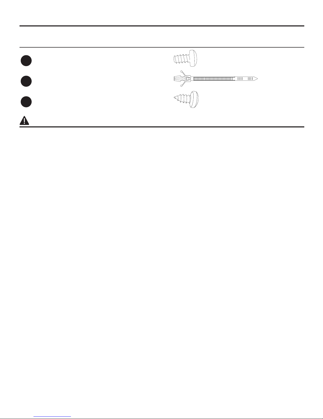
Style selections NAOS K4 User manual

ITEM #0293810
BLOWER ACCESSORY
Questions, problems, missing parts? Before returning to your retailer, call our
customer service department at 1-866-573-0674, 8:00 a.m - 4:30 p.m., EST,
LS-FANFIB-0901
MODEL #SSFIB100
Español p. 24

2
PART PART NUMBER DESCRIPTION Quantity
A XB001-01 Power Cord 1
B XB002-01F Blower 1
C XB003-01 Temperature Sensor 1
D XB004-01F Connect Wire 1
E PF06-0400-A Rocker Switch 1
PACKAGE CONTENTS
A
C
B
D
E

3
HARDWARE CONTENTS
AA
6
6
Cable Tie
M4.2X8 Screw
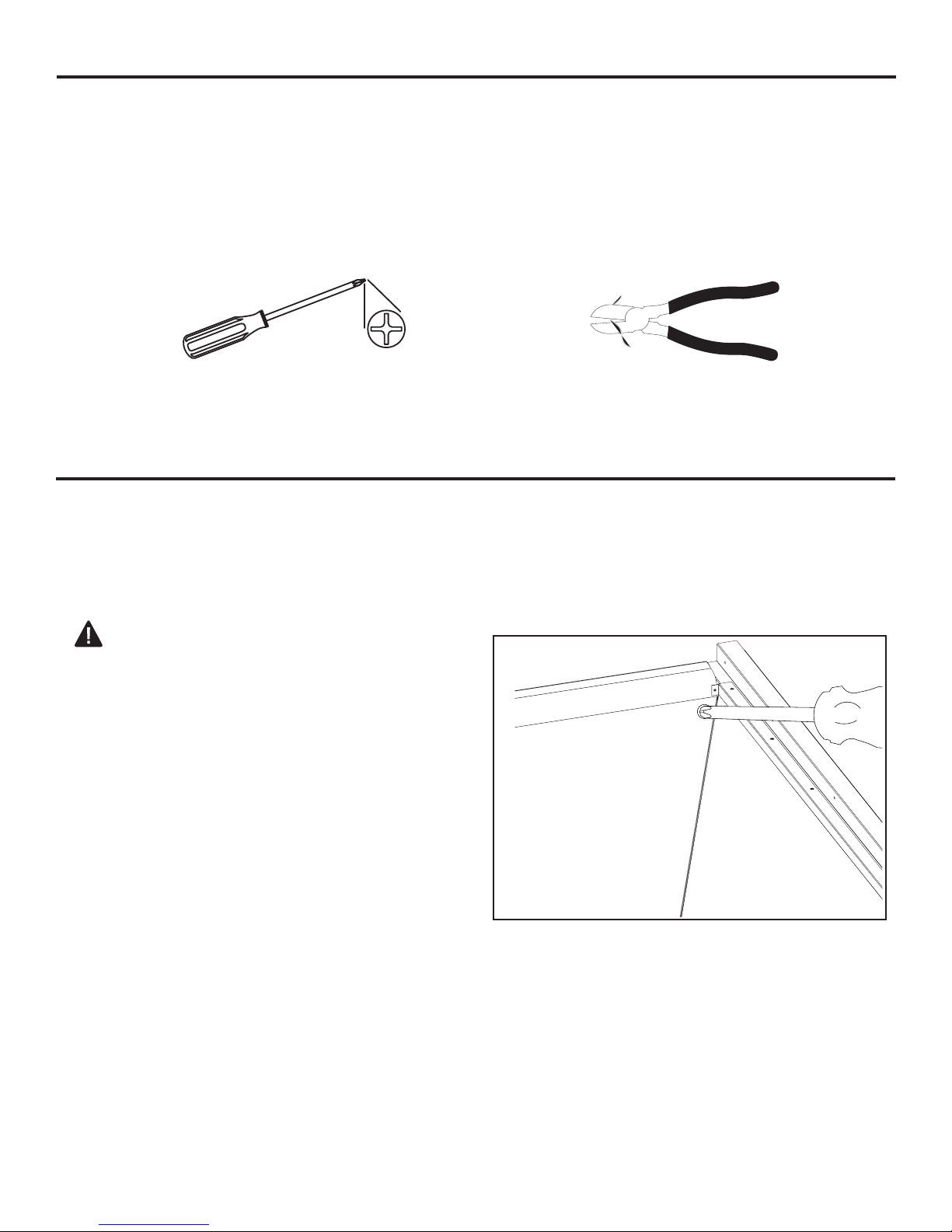
WARNINGS AND CAUTIONS
WARNING
• Read all instructions and warnings carefully before starting installation. Failure to follow these
instructionsmayresultinapossibleelectricshock,rehazardandwillvoidthewarranty.
• Read all instructions before using this appliance.
• If possible always unplug this appliance when not in use.
• Do not operate any heater with a damaged cord or plug or after the appliance malfunctions,
has been dropped or damaged in any manner.
• Anyrepairstothisapplianceshouldbecarriedoutbyaqualiedserviceperson.
• Undernocircumstancesshouldthisappliancebemodied.Partshavingtoberemovedfor
servicing must be replaced prior to operating this appliance again.
• Do not use outdoors.
• This heater is not intended for use in bathrooms, laundry areas and similar indoor locations.
Never locate this appliance where it may fall into a bathtub or other water container.
• Do not run cord under carpeting. Do not cover cord with throw rugs, runners or the like.
Arrangecordawayfromtrafcareasandwhereitwillnotbetrippedover.
• To disconnect this appliance, turn controls to the off position, then remove plug from outlet.
• Connect to properly grounded outlets only.
• This appliance, when installed must be electrically grounded in accordance with local codes,
with the current CSA C22.1 Canadian Electrical codes or for USA installations, follow local
codes and the National Electric Code, ANSI/NFPA No. 70.
• Do not insert or allow foreign objects to enter any ventilation or exhaust opening as this may
causeanelectricshock,reordamagetheappliance.
• Topreventpossiblere,donotblockairintakesorexhaustinanymanner.
• Use this appliance only as described in this manual. Any other use not recommended by the
manufacturermaycausere,electricshockorinjurytopersons.
• Avoid the use of an extension cord because of the risk of overheating the cord and the risk
ofre.Extensioncordsarefortemporaryuseonly.Ifanextensioncordmustbeused,it
mustbeUL/CSAcertied,ratedat15A(1875W),125Vmaximumwith14AWGminimumand
constructed of two current carrying conductors with ground. A heavy duty extension cord with
the shortest length possible for the connection is recommended and must not be longer than
50ft.(15.2m).Donotcoilorcovertheextensioncord.
BB
CC 1M4.0X8 Screw
Picture
Part Description Quantity (Showntosize)
Notshowntosize

4
Fig. 1
ASSEMBLY INSTRUCTIONS
PREPARATION
Before beginning assembly of product, make sure all parts are present. Compare parts with
package contents list. If any part is missing or damaged, do not attempt to assemble the
product. Contact customer service for replacement parts.
Estimated Assembly Time: 30 minutes
Tools Required for Assembly: Philips Screwdriver and Wire Cutter
This blower contains assembly instructions for the following models and item numbers
SSFBD28T (Item # 0030334). For the SSFBD32RT (Item # 0293807), see page 12 - 18.
1.Removeupperreboxbyunscrewing
left/rightscrewsontherebox.SeeFig.1.
Before installing the blower, be certain
to turn off the unit, and allow time for
unit to cool down.

5
Fig. 2
Fig. 3
2. Unscrew two screws on heat insulation
board cover and draw it out. See Fig. 2.
3.Afxtemperaturesensor(C)toheat
insulation board cover with M4.2X8 screws
(AA).SeeFig.3.
Hardware Used
M4.2X8 screw x2
AA
c
AA

6
Fig. 4
4. Insert wires into the space between wire
protecting board and shell; Fix the wires to
thetopcoverwithwirexture.SeeFig.4.
5.Connecttemperaturesensor(C)with
connectwire(D).Installthecoveraccording
toFigure2,thenxtheupperrebox
according to step 1. See Fig. 5.
Fig. 5
Protecting
Board
Wire
Fixture
D
C
Wire
Fixture
Protecting
Board

7
Fig. 6
6.Insertblower(B)intothebottomspaceof
burner pan. Pay attention not to touch wires
inside. See Fig. 6.
Fig. 7
7.Setblower(B)planeandafxontotwo
brackets of shell board. Make sure blower
(B)isinstalledintotheslots.SeeFig.7.
B
Install
Blower
Into slots B
Install
Blower
Into slots

8
Fig. 8
8.AfxblowerwithM4.0X8screws(CC),
after, manually install it into slots. See Fig. 8.
Hardware Used
M4.0X8 screw x1
CC
Fig. 9
9.Attachthepowercord(A)tothereplace
withM4.2X8screws(AA)onthetopcover.
See Fig. 9.
Hardware Used
M4.2X8 screws x3
AA
cc
AA
A

9
Fig. 10
10.AfxthegroundingterminalwithM4.2X8
screw(AA).SeeFig.10.
Fig. 11
11.Insertthemaleportofblower(B)andin
to the corresponding female port. See Fig. 11.
Fig. 12
12. Connect the AUTO, OFF, MAN wires to
the three corresponding male tabs on the
rockerswitch(E).SeeFig.12
Hardware Used
M4.2X8 screw x1
AA
AA
B
Male Port
Female Port
E
AUTO
OFF
MAN
Female Port Male Port

10
Fig. 13
13. Push the rocker switch into the hole on
the panel. See Fig. 13.
Fig. 14
14. Insert the male port, which is on the black
powersupplywire(markedwithP2),intothe
correspondingfemaleport(markedwithP2).
See Fig. 14.
Fig. 15
15. Insert the female port, which is on the white
powersupplywire(markedwithP1),intothe
correspondingmaleport.(markedwithP1).
See Fig. 15.
E
P2
P1

11
Installation blower assembly position
Install temperature sensor
Install wire
and grounding
Install rocker
switch
Install blower
Install wire
and grounding
Install rocker
switch
Install blower
Install temperature sensor

12
Fig. 1
1.Removeupperreboxbyunscrewingleft
/rightscrewsontherebox.SeeFig.1.
Before installing the blower, be certain
to turn off the unit, and allow time for
unit to cool down.
Instructions for model # SSFBD32RT (Item # 0293807).
Fig. 2
2. Unscrew two screws on heat insulation
board cover and draw it out. See Fig. 2.

13
Fig. 3
3.Afxtemperaturesensortoheatinsulation
boardcoverwithM4.2X8screws(AA).
See Fig. 3.
Hardware Used
M4.2X8 screw x2
AA
Fig. 4
4. Insert wires into the space between wire
protecting board and shell; Fix the wires to
thetopcoverwithwirexture.SeeFig.4.
c
AA
Protecting
Board
Wire
Fixture
Protecting
Board
Wire
Fixture

14
5.Connecttemperaturesensor(C)with
connectwire(D.Installthecover
accordingtoFigure2,thenxtheupper
reboxaccordingtoFig.1.SeeFig.5.
Fig. 5
6. Unscrew and remove panel on the left
side. See Fig. 6.
Fig. 6
D
C

15
Fig. 7
7.Insertblower(B)intothebottomspaceof
burner pan. Pay attention not to touch
wires inside. See Fig. 7.
Fig. 8
8.Setblower(B)planeandxitontotwo
brackets of shell board. Make sure blower
(B)isinstalledintotheslots.SeeFig.8.
B
Install
Blower
Into slots B
Install
Blower
Into slots

16
Fig. 9
9.Afxblower(B)withM4.0X8screws(CC),
after, manually install it into slots. See Fig. 9.
Hardware Used
M4.0X8 screw x1
CC
Fig. 10
10.Attachthepowercord(A)tothereplace
withM4.2X8screws(AA)onthetop
cover. See Fig. 10.
Hardware Used
M4.2X8 screws x3
AA
cc
AA
A

17
Fig. 11
11.AfxthegroundingterminalwithM4.2X8
screw(AA).SeeFig.11.
Fig. 12
12.Insertthemaleportofblower(B)andin
to the corresponding female port.
See Fig. 12.
Fig. 13
13. Connect the port and shell board with
linker(maleport)intothethreewires
withprotectingjacket(pleasereferto
linker(femaleport)(red,yellowand
black)withgroundinglabel);Put
protectingjacketintorockerswitch(E)
corresponding. See Fig. 13.
Hardware Used
M4.2X8 screw x1
AA
AA
B
Male Port
Female Port
E
AUTO
OFF
MAN
Female Port Male Port

18
Fig. 14
14. Push the rocker switch into the hole on
the panel. See Fig. 14.
Fig. 15
15. Insert the male port, which is on the black
powersupplywire(markedwithP2),intothe
correspondingfemaleport(markedwithP2).
See Fig. 15.
Fig. 16
16. Insert the female port, which is on the white
powersupplywire(markedwithP1),intothe
correspondingmaleport.(markedwithP1).
See Fig. 16.
E
P2
P1

19
Installation blower assembly position
Install temperature sensor
Install wire
and grounding
Install rocker
switch
Install blower
ELECTRICAL CONNECTION
A15amp,120Volt,60Hzcircuitwithaproperlygroundedoutletisrequired.Preferably,the
replacewillbeonadedicatedcircuitasotherappliancesonthesamecircuitmaycausethecircuit
breaker to trip or the fuse to blow when the heater is in operation. Plan the installation to avoid the
use of an extension cord. Extension cords are for temporary use only. If an extension cord must be
used,itmustbeUL/CSAcertied,ratedat15A(1875W),125Vmaximumwith14AWGminimum
and constructed of two current carrying conductors with ground. A heavy duty extension cord with
the shortest length possible for the connection is recommended and must not be longer than 50 ft.
(15.2m).Donotcoilorcovertheextensioncord.
Electrical outlet wiring must comply with local building codes and other applicable regulations to
reducetheriskofre,electricalshockandinjurytopersons.
Donotusethisreplaceifanypartofithasbeenunderwater.Immediatelycallaqualied
servicetechniciantoinspectthereplaceandreplaceanypartoftheelectricalsystemwhich
has been under water.
Install wire
and grounding
Install rocker
switch
Install blower
Install temperature sensor

20
GROUNDING INSTRUCTIONS
This heater is for use on 120 volts. The cord has a plug as shown at A in Fig. 22. An adapter as
shown at C is available for connecting three-blade grounding-type plugs to two-slot receptacles.
The green grounding lug extending from the adapter must be connected to a permanent ground
such as a properly grounded outlet box. The adapter should not be used if a three-slot grounded
receptacle is available.
Fig. 17
OPERATING INSTRUCTIONS
Using rocker switch, turn blower on and check for operation. Turn on rocker switch to the desired
position. In the MAN position it will remain constantly on. AUTO position will be controlled by the
temperature sensor. To stop the operation turn rocker switch to the Oposition.
Grounding Pin
Adapter
Grounding Means
Metal Screw
Cover of
Grounded
Outlet Box
This manual suits for next models
1
Table of contents