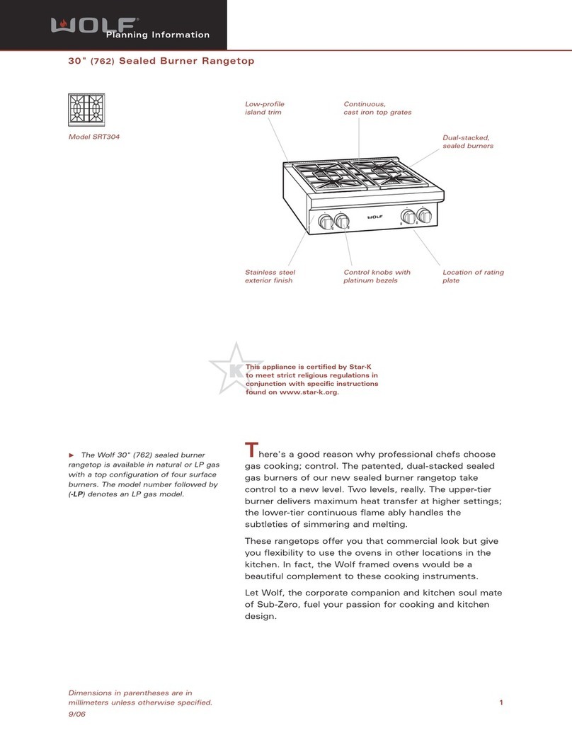
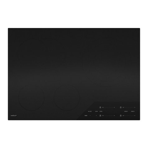
Sub-Zero WOFL CG User manual

Page 2
Cooktop Gas (CG) Series
General Information
1-2
#824779 - Revision B - October, 2016
INTRODUCTION
This Technical Service Manual has been compiled to provide the most recent technical service information. This
information enables the service technician to troubleshoot and diagnose malfunctions, perform necessary repairs
and return the appliance to proper operational condition.
The service technician should read the complete instructions contained in this service manual before initiating any
repairs on a Wolf Appliance.
For installation information see Gas Cooktops Installation Guide available at http://www.subzero-wolf.com/trade-
resources/product-specifications.
For Use and Care information see Gas Cooktops Use & Care Guide available at http://www.subzero-
wolf.com/trade-resources/product-specifications.
* Some information in Section 2, Theory of Operation, has been provided by the American Gas Association
and reprinted with their approval.
IMPORTANT SAFETY INFORMATION
Below are the Product Safety Labels used in this manu-
al. The "Signal Words" used are WARNING and
CAUTION.
Please note that these safety labels are placed in areas
where awareness of personal safety and product safety
should be taken and lists the precautions to be taken
when the signal word is observed.
INDICATES THAT HAZARDOUS OR UNSAFE
PRACTICES COULD RESULT IN SEVERE PERSON-
AL INJURY OR DEATH.
Indicates that hazardous or unsafe practices could
result in minor personal injury or product and/or
property damage.
In addition, please pay attention to the signal word
“NOTE”, which highlights especially important informa-
tion within each section.
TECHNICAL ASSISTANCE
If you should have any questions regarding the appli-
ance and/or this manual, please contact:
Wolf Appliance, Inc.
ATTN: Service Department
P.O. Box 44988
Madison, WI 53744 - 4988
Customer Assistance
Phone #: (800) 332 - 9513
Facsimile #: (608) 441 - 5887
Technical Assistance
(For Technicians in Customer’s Homes Only)
Phone #: (800) 919 - 8324
Warranty Claims
Phone #: (800) 404 - 7820
Facsimile #: (608) 441 - 5886
Service Department e-mail Address:
Main Office Hours:
8:00 AM to 5:00 PM Central Time
Monday through Friday
(24/7 Phone Coverage)
This manual is designed to be used by Certified Service Personnel only. Wolf Appliance, Inc.. assumes no
responsibility for any repairs made to Wolf appliances by anyone other than Certified Service Technicians.
The information and images are the copyright property of Wolf Appliance, Inc., an affiliate of Sub-Zero Group, Inc.
Neither this manual nor any information or images contained herein may be copied or used in whole or in part with-
out the express written permission of Wolf Appliance, Inc., an affiliate of Sub-Zero Group, Inc. ©
Wolf Appliance, Inc. all rights reserved.

Page 3
General Information
Cooktop Gas (CG) Series
1-3 #824779 - Revision B - October, 2016
WARRANTY INFORMATION
This page contains a summary of the 2 & 5 Year Warranty that is supplied with every Wolf product, followed by Non-
Residential Warranty Summary and then notes about the warranties.
TWO & FIVE YEAR Warranty Summary
• Two year TOTAL PRODUCT warranty, parts and labor.
• Limited Parts Only Warranty for the 3rd through 5th year on select parts.
Details:
Warranty applies to products installed in United States or Canada, for residential use only.•
Warranty begins at time of unit’s initial installation.•
Warranty does not cover Wolf Appliances installed in a demonstration kitchen, test kitchen, culinary school•
kitchen, or similar installations (See Special Warranty below).
Warranty and service information collected by Wolf Appliance, Inc. is arranged and stored under unit serial num-•
ber and/or customer’s name. Wolf Appliance, Inc requests that you have model and serial number available
whenever contacting factory or parts distributor.
3-5 Year Limited Parts Only Warranty applies to the Light Display boards, and Gas Burners (excluding appear-•
ance).
Special Warranty Summary
2 Year Total Product Warranty, parts and labor.
Details:
This Warranty applies to products installed in United States or Canada, for use in a demonstration kitchen, test•
kitchen, culinary school kitchen, and similar installations that help promote Wolf Appliance brand and its prod-
ucts.
Warranty begins at time of unit’s initial installation.•
Warranty and Service information collected by Wolf Appliance, Inc. is arranged and stored under unit serial num-•
ber and/or customer’s name. Wolf Appliance, Inc. requests that you have model and serial number available
whenever contacting factory or parts distributor.
Figure 1-1. Typical Serial Tag Layout
Serial Tag Location
Figure 1-2. Serial tag is located on bottom.

Page 4
Cooktop Gas (CG) Series
General Information
1-4
#824779 - Revision B - October, 2016
MODEL NUMBER KEY
Refer to this key for an example of model numbers.
Model: C G 36 5 P / S -LP
Cooktop
Type
Size
# of Burners
Style
Finish
Fuel
Product
CCooktop
Type
GGas
EElectric
IInduction
Size
15”, 24”, 30” and 36”
Number of Burners
2, 3, 4 or 5
Style
PProfessional
TTransitional
CContemporary
Finish
SClassic Stainless Steel
Fuel
LP Liquid Propane Gas
Natural Gas (If there is no “LP” at End of Model Number)

Page 5
General Information
Cooktop Gas (CG) Series
1-5 #824779 - Revision B - October, 2016
MODEL CONFIGURATIONS
Model Numbers Descriptions
CG304P/S Cooktop Gas 30” Four burners Professional Stainless Steel Natural Gas
CG304P/S - LP Cooktop Gas 30” Four burners Professional Stainless Steel Liquid Propane (LP).
CG304T/S Cooktop Gas 30” Four Burners Transitional Stainless Steel Natural Gas
CG304T/S - LP Cooktop Gas 30” Four Burners Transitional Stainless Steel Liquid Propane (LP)
• One burner at 18,000 BTU/hr - Front Left.
• One burner at 12,000 BTU/hr - Rear Right.
• Two burners at 9,200 BTU/hr - Rear Left and Front Right.
30” Gas
36” Gas
Model Numbers Descriptions
CG365P/S Cooktop Gas 36” Five burners Professional Stainless Steel Natural Gas
CG365P/S - LP Cooktop Gas 36” Five burners Professional Stainless Steel Liquid Propane (LP)
CG365T/S Cooktop Gas 36” Five burners Transitional Stainless Steel Natural Gas
CG365T/S - LP Cooktop Gas 36” Five burners Transitional Stainless Steel Liquid Propane (LP)
CG365C/S Cooktop Gas 36” Five burners Contemporary Stainless Steel Natural Gas
CG365C/S - LP Cooktop Gas 36” Five burners Contemporary Stainless Steel Liquid Propane (LP)
Professional and Transitional
• One burner at 18,000 BTU/hr - Front Left.
• One burner at 12,000 BTU/hr - Rear Center.
• Three burners at 9,200 BTU/hr - Rear Left, Front Right, Rear Right.
CG304T
CG304P
CG365P CG365T CG365C
Contemporary
• One burner at 20,000 BTU/hr - Center.
• Two burners at 12,000 BTU/hr - Left Front and Right Rear.
• Two burners at 9,200 BTU/hr - Left Rear and Right Front.

Page 6
Cooktop Gas (CG) Series
General Information
1-6
#824779 - Revision B - October, 2016
MODEL FEATURES for 30” & 36” COOKTOPS GAS (CG)
• Simmer on all burners
• Dual stacked sealed burners
• Single spark ignition with auto reignition for all burners
• 20,000 BTU/hr burner on 36” Contemporary units.
• 18,000 BTU/hr burner on 30” and 36” Professional and Transitional units.
12,000 BTU/hr and 9,200 BTU/hr burners•
• Low profile, continuous, porcelain-coated cast iron grates
• Electric ratings: 110-120V/ 15 amp dedicated circuit
• Available in Natural or LP gas
• Two and Five year warranty
Single continuous pan floor for easy cleaning•
Transitional unit has backlit glass plate•
Professional unit has lighted indicator on knob.•
Contemporary manifold installs through cabinet front at an adjustable distance.•
Contemporary knobs are lit from the rear by an integrated light module.•

Page 7
Cooktop Gas (CG) Series
Theory of Operation
2-2
#824779 - Revision B - October, 2016
OPERATION INFORMATION
A service technician should understand how a gas appliance operates before attempting to service the appliance.
This section provides descriptions of the different types of fuel gases and explains gas heating values. A definition
of specific gravity of gas is given along with its characteristics and effects. Gas combustion principles are explained
and gas burner components are described and illustrated. The end of this section contains illustrations which
demonstrate basic cooking appliance theory of operation.
Types of Fuel Gas:
Gases used to supply heat energy are called fuel gases. Common fuel gases are not simply one kind of hydrocar-
bon, they are mixtures of hydrocarbon gases. They contain other gases as well, such as free hydrogen, carbon
dioxide and nitrogen. As an example, natural gas might contain 85% methane, 12% ethane and 3% of other gases.
The presence of each of these gases in the fuel gas has some effect on the nature of the gas.
Some common fuel gasses are methane [CH4], ethane [C2H6], Propane [C3H8] and butane [C4H10]. Propane and
butane are nearly odorless. Natural gas that is processed to remove condensables and moisture, has little or no
odor and no color. Odorants are added to natural gas before distribution to aid in leak detection. A common odorant
used is a colorless liquid containing sulfur compounds.
Heating Value of Gas:
Heat energy produced when burning a fuel gas is commonly expressed in British Thermal Units (BTU). One BTU of
heat will raise the temperature of one pound of water one degree Fahrenheit.
The more carbon and hydrogen atoms in each molecule of a fuel gas, the higher its heating value. Natural gas
which is high in methane has a heating value of about 950 to 1150 BTU per cubic foot. The variance is due to vari-
ous other substances found in natural gases. The more ethane, propane or butane in the gas raises the heating
value. Propane, or LP gas, has a heating value of about 2500-2800 BTU per cubic foot, and butane about 3200
BTU per cubic foot.
Specific Gravity of Gas:
The specific gravity of a gas is the weight of one cubic foot of the gas compared to one cubic foot of dry air. When
stating the specific gravity of a gas, a pressure and temperature must be clearly stated. In the gas industry, the
standard conditions of pressure and temperature are 30.0 inches of mercury and 60° F. A pressure of 30.0 inches of
mercury will sustain a column of mercury 30 inches high in a tube with a vacuum on top of the column. Since air is
used as the reference, its specific gravity is always 1.0. This value of 1.0 has no direct physical meaning with
regard to air, such as its density. It is only a relative number or ratio used to express specific gravity of other gases.
The specific gravity of a gas will determine if the gas will rise or fall when released into the air. Natural gas will rise
since its specific gravity is less than 1.0 at 0.4 to 0.8. Propane has a specific gravity of 1.5 and butane 2.0. These
gases will fall when released into the air. Gases with a specific gravity greater than 1.0 can sometimes pool in low
spots, which become a hazard if a spark or open flame is present.
In addition, specific gravity has two other characteristics. It has an important effect on the flow of gases through ori-
fices, and hence the rating of the burners. Gas flow through an orifice is dependent upon the orifice size and the
gas pressure upstream of the orifice. More of a lighter gas will flow through a given orifice size than a heavier gas
at the same gas pressure. This effect is taken into account in tables and calculators used to select orifice sizes for
burners.
Specific gravity also affects gas flow in pipes. A given driving pressure at a pipe inlet will move more lighter gas
than heavier gas through that pipe.

Page 8
Theory of Operation
Cooktop Gas (CG) Series
2-3 #824779 - Revision B - October, 2016
PRINCIPLES OF GAS COMBUSTION:
Combustion - When oxygen acts with a substance to produce large amounts of heat rapidly.
Requirements for Combustion - There are three required elements for combustion to occur; Fuel (Gas), Oxygen
(Air) and Heat (Ignition Temperature, which for gas is between 1100°F/593°C and 1200°F/649°C). All must be pres-
ent. Removing any one of the three and combustion will cease.
Chemistry of Combustion - Combustion of gas is a chemical reaction between fuel gas and oxygen. The basic
elements of common fuel gasses are hydrogen [H] and carbon [C]. When hydrogen burns, water vapor [H2O] is pro-
duced. Complete burning of carbon in fuel gases form carbon dioxide [CO2] and water vapor [H2O].
Controlled Combustion - Controlled combustion takes place when gas and air are supplied at proper rates to
assure complete combustion of the gas in a steady flame. When a gas appliance is operating properly, burning
starts at the burner ports. Gas flow is controlled by gas orifice size and gas pressure upstream of the orifice. Air is
mixed with the gas before it passes through the burner ports. This added air is called “Primary Air”. The remaining
air required for complete combustion is supplied to the burner at the point of combustion and is called “Secondary
Air”.
Adjustments of the gas-to-air ratio and the secondary air supply is the key to obtaining stable blue flames at a burn-
er. Proper amounts of primary and secondary air are required for quiet and efficient burner operation and for com-
plete combustion of the gas. Air Shutters or other devices provide control of primary air. Inlet opening and flue out-
lets control Secondary Air flow.
Total air - In an ideal situation, primary and secondary air is all that is needed (for the oxygen required) to burn the
gas, but some additional air is required to assure complete burning of the gas. The total air, “primary”, “secondary”
and “excess” are expressed as percentages of the amount needed. About ten cubic feet of air is required to com-
pletely burn one cubic foot of gas. For this reason an appliance should not be operated in an air tight home.
Limits of Flammability - Not all air-to-gas mixtures will burn. Mixtures with 0% - 4% natural gas in air are too lean
to burn. Mixtures of 4% - 14% natural gas in air can burn with a controlled flame. Flammability limits come into play
when primary air adjustments are made on burners. If too much primary air is used, the mixture may become too
lean and fall below flammability limits, thus preventing combustion.
Incomplete Combustion (Causes and Effects) - To obtain complete combustion, sufficient amounts of air must be
supplied to the process. This air must have a reasonably normal oxygen content. Complete burning of gas pro-
duces harmless carbon dioxide gas and water vapor. If the air supply is insufficient, incomplete combustion occurs
resulting in the formation of toxic by-products, such as carbon monoxide [CO] or aldehydes.
Carbon monoxide is colorless and odorless. Inhaling carbon monoxide in sufficient quantities could cause death by
reducing oxygen levels in the blood.
Aldehydes, which are equally dangerous, have a sharp and penetrating odor which is easily detected by smell at
very low concentrations. The odor caused by aldehydes should not be confused with odorants added to natural gas.
The absence of aldehydes does not assure that carbon monoxide is not present. However, if the odor of aldehydes
is present, then carbon monoxide is virtually always present.
Gas Burner Operation - A gas burner is a device to burn gas under control in order to produce useful heat.
Primary air is brought into the burner from outside of the appliance at atmospheric pressure. The gas jet streaming
from the orifice draws primary air with it into the burner. The gas/air mixture, combined with a spark at the burner
port(s) and the secondary air creates a controlled burn.

Page 9
Cooktop Gas (CG) Series
Theory of Operation
2-4
#824779 - Revision B - October, 2016
30” and 36” Burner Components
Burner Components:
Burner Cap - Provides upper portion of ports required to create a combustible mix and proper flame quality of burn-
er and the decorative top for burner with a black porcelain coating.
Burner Assembly - Contains burner ports where gas/air mixture ignites. The burner ports are distributed in a use-
ful pattern to optimize heat transfer. Flames should be spread so they can be easily reached by secondary air and
provide a stable blue flame. The burner also incorporates the inner ring, which routes gas from the simmer orifice to
simmer port holes on the Burner Assembly, and an outer ring, which routes gas from the main burner orifice to the
main burner port holes on the Burner Assembly.
Venturi - Helps maintain proper and constant primary air injection.
Electrode - The Electrode supplies the spark to ignite the burner. The Electrode senses flame once the burner is
ignited and will stop sparking. If no flame is sensed or of poor quality, and the valve is open, the electrode will start
sparking to re-ignite the flame. This is part of the auto-reignition system.
Orifice Holder - This component is mounted to burner mounting bracket and to the burner box. The Simmer and
Main orifice is threaded into Orifice Holder and routes the gas to the appropriate rings of burner assembly. It is the
main support for the burner components.
Simmer Orifice and Main Orifice - An opening or hole which regulates or limits the amount of gas flowing to a
burner. Gas flow rate (volume) depends on the size of the orifice (hole) and the gas pressure at the inlet of the ori-
fice.
Burner Cap
Burner Assembly
Electrode
Orifice Holder
Venturi
Simmer Orifice
Main Orifice

Page 10
Theory of Operation
Cooktop Gas (CG) Series
2-5 #824779 - Revision B - October, 2016
OPERATION OF THE 30” and 36” WOLF COOKTOP GAS
Surface Burners
A spark electrode ignites each surface burner. This control eliminates need for continuous open flame pilots. For
added safety and convenience, each burner is designed with an electronic re-ignition system. This feature enables
any burner to automatically re-light in the event it is accidentally extinguished.
This cooktop has a unique dual stacked burner design that combines all the burner parts in one configuration. Large
burners provide a Btu/hr rating of 18,000 on HIGH. Medium burnes provide a Btu/hr rating of 12,000 on High.
Small burners provide a Btu/hr rating of 9,200 on HIGH. All burners have simmer settings.
A distinguishing feature of Wolf’s low Btu/hr control is its constant, low heat output without continuous ignitions.
Flame diameter remains full size, only the heat output is lowered. This is the ultimate control for simmering food.
Grate Placement
Low profile porcelain coated cast iron grates are designed for a close fit. This enables pans to move easily from one
burner to another without having to lift the pan or have it tip over between grates. Each grate sets securely on dim-
ples on each corner of the cooktop pan. Continuous grates are interchangeable with the exception of the single
grate.
Burner Lighting
Each burner has full flame and full simmer capabilities. Knobs are designed as a two- tiered, “push-to-turn” knob.
One tier is used for HIGH through LOW flame settings. Second tier controls SIMMER settings. Push down and turn
the corresponding control knob counter clockwise to the HIGH setting. You will hear “clicking” and see the burner
ignite. Once the burner is lit, continue turning the knob counter clockwise to any one of settings, HIGH through
LOW.
To select a simmer setting, turn the knob to the LOW setting. You will feel a stop-detente in knob rotation. Push
down on the knob, continuing to turn it counter clockwise. This moves it to the second tier. Now, select any varia-
tion within the SIMMER flame settings, HIGH through LOW.
Note: When moving from Low to Simmer it is possible the flame will go out then reignite.

Page 11
Component Removal Cooktop Gas (CG) Series
Cooktop Gas (CG) Series
#824779 - Revision B - October, 2016 3-2
COMPONENT REMOVAL - PROFESSIONAL AND TRANSITIONAL MODELS
This section explains how to remove components from the Wolf Cooktop Gas Transitional and Professional models.
The Wolf Cooktop Gas Contemporary is constructed differently and has a separate section after the Traditional and
Professional models. Depending on which component you are going to remove, you may have to remove other
components first. Refer to appropriate section in this manual that explains how to access and remove those various
components. When reassembling, reverse steps that were used to remove components.
COMPONENT REMOVAL - CONTEMPORARY MODEL (CG365C)
Starting on Page 3-10 is the contemporary model component removal section. While the components are like the
Transitional and Professional models, the construction of the unit is unique. Please refer to this portion of the man-
ual when accessing a contemporary model.
NOTES:
Access to individual spark modules can be obtained through access panels on the bottom of unit burner•
box.
Before attempting to access or remove any components from a Wolf Appliance, take note of the following•
warnings.
TO AVOID SERIOUS BURNS AND/OR EXPLOSIONS, KEEP COMBUSTIBLES AWAY FROM APPLIANCE
WHENEVER A FLAME IS PRESENT. SURFACES AND COMPONENTS GET HOT DURING THE USE OF THE
APPLIANCE.
TO AVOID ELECTRICAL SHOCK, POWER TO UNIT MUST BE DISCONNECTED WHENEVER ACCESSING
AND/OR REMOVING COMPONENTS POWERED BY ELECTRICITY OR COMPONENTS NEAR OTHER ELEC-
TRICAL COMPONENTS.
TO AVOID POSSIBLE GAS LEAKS AND/OR EXPLOSIONS, GAS TO UNIT MUST BE SHUT OFF AT SUPPLY
SOURCE WHENEVER ACCESSING AND/OR REMOVING COMPONENTS.
WHEN REASSEMBLING GAS SUPPLY LINE TO REGULATOR, ONLY PIPE THREAD COMPOUND SHOULD
BE USED. DO NOT USE TEFLON TAPE TO SEAL GAS PIPE CONNECTIONS.
WHEN REASSEMBLING REGULATOR TO MANIFOLD, ONLY PIPE THREAD COMPOUND SHOULD BE
USED. DO NOT USE TEFLON TAPE TO SEAL GAS CONNECTIONS.

Page 12
Component Removal
Cooktop Gas (CG) Series
3-3 #824779 - Revision B - October, 2016
Surface Burner Components
Preliminary Steps
•Disconnect power cord from electrical supply source.
•Turn off gas supply source to cooktop.
Burner Grate and Burner Assembly
Burner grates locate on raised dimples formed on burn-
er pan. Burner assemblies have screws that pass
through Burner assemblies then thread into orifice hold-
er located under burner pan. Burner caps are then
placed over Burner assembly.
To remove burner assembly (See Figure 3-1).
1. Remove burner grate from unit.
2. Remove burner caps from burner assembly.
3. Use T-15 to extract two screws securing burner
assembly to orifice holder.
4. Lift assembly off burner pan and remove wire lead
from spark ignitor.
5. To remove spark ignitor from burner assembly,
extract screw from underside of burner assembly
and separate.
NOTE: Burner assembly screws should be torqued to
24 inch-pounds.
Figure 3-1. Burner Assembly Removal
Figure 3-2. Below Burner Pan - Transitional Unit
Burner Cap
Screws Burner Assembly
Ignitor
Screw
Wire Lead
Burner Pan Removal
1. Uninstall unit
2. Remove Burner Assemblies.
3. Remove Knobs.
4. Remove Knob Bezels:
Professional: Twist bezel 90 degrees counter-•
clockwise. Disconnected bezel from light har-
ness.
Transitional: Use a 3/4” wrench to remove•
bezel.
5. Lift Burner Pan from burner box. (See Figure 3-2
and Figure 3-3)
Unit is supported by burner pan. Unit must be
uninstalled if all burner assemblies, knob bezels, or
burner pan is going to be removed.
Figure 3-3. Below Burner Pan - Professional Unit

Page 13
Component Removal Cooktop Gas (CG) Series
Cooktop Gas (CG) Series
3-4
#824779 - Revision B - October, 2016
Orifice Removal
The main and simmer Orifice are threaded into the ori-
fice holder and may be extracted without removing ori-
fice holder from its position.
To remove an orifice,
1. Remove burner assembly.
2. Use a 9/32” box wrench or socket with extension, to
extract orifice from orifice holder. (See Figure 3-4)
Orifice Holder
Each orifice holder assembly consists of an orifice hold-
er, main and simmer orifice, sealed burner bracket and
mounting hardware. Two screws secure orifice holder to
sealed burner bracket.
To remove orifice holder,
1. Remove burner pan.
2. Use a 3/8” open end wrench to remove the simmer
gas line. Use a 1/2” open end wrench to remove
main gas line (See Figure 3-5).
3. Extract two screws securing orifice holder to sealed
burner bracket.
NOTES:
Support burner tube as much as possible while•
removing or installing tubes.
Do not over torque brass fittings.•
If burner tube was kinked it must be replaced.•
18k and 15k Orifice Holder appear exactly the•
same. Screw holes on 18k Orifice holder have
been offset so that they can not be accidently inter-
changed.
WHEN REASSEMBLING ORIFICE TO ORIFICE
HOLDER, ONLY PIPE THREAD COMPOUND
SHOULD BE USED. DO NOT USE TEFLON TAPE
TO SEAL GAS CONNECTIONS.
Figure 3-4. Orifice Removal
Figure 3-5. Orifice Holder Removal
Orifice Holder
Screw
Gas Line
Hat Bracket
Simmer Orifice
Main Orifice

Page 14
Component Removal
Cooktop Gas (CG) Series
3-5 #824779 - Revision B - October, 2016
Figure 3-6. 30” Transitional Display Bracket
Display Area Components
Display Bracket, Display Light Board, Valve Switch,
and Valve.
To access these items requires removal of Display
Bracket.
Preliminary Steps
Unplug the power cord from electrical supply•
source.
Turn off gas supply source to cooktop.•
Remove grates.•
Uninstall unit.•
Remove burner assemblies.•
Remove burner pan.•
Display Bracket Removal - Transitional models
Transitional units have a display bracket beneath the
burner pan.
Transitional units have a knob bushing attached to•
Display bracket where knob bezel screws into.
1. Extract phillips screws holding Display Bracket to
manifold support brackets (See Figure 3-6).
Display Light Board - Transitional models
On Transitional models there is a Display Light board
beneath display bracket.
1. Disconnect wire harness connector from J1 on
Display Light board.
2. Extract phillips screws holding Display Light board
to manifold support bracket (See Figure 3-7).
Phillip
Screws
Knob
Bushing
Phillips Screws
Harness Connector
Figure 3-7. 36” Light Display Board

Page 15
Component Removal Cooktop Gas (CG) Series
Cooktop Gas (CG) Series
3-6
#824779 - Revision B - October, 2016
Display Bracket Removal - Professional models
Prior to Serial #18141496
Professional units prior to serial #18141496 have a dis-
play bracket beneath the burner pan.
Professional units have a cut out in Display Bracket•
for knob bezels to lock into place. Bezel electrical
connectors can be seen passing through Display
Bracket bezel openings.
1. Extract phillips screws holding Display Bracket to
manifold support brackets (See Figure 3-8).
Professional model Bezel Removal Starting With
Serial #18141496
Professional units starting with Serial #18141496 have
a receptacle mounted to the valve, and a lighted bezel
that locks into the pan.
To remove the bezel on a professional model, first
remove the knob, then (See Figure 3-9):
Twist bezel counter-clockwise to remove it from the1
pan.
Pull bezel from the pan and disconnect the electri-2
cal connector.
Remove the bezel.3
Professional Model Receptacle Removal Starting
With Serial #18141496
To remove the receptacle on a professional model, first
remove the pan, then (See Figure 3-9):
Extract the screws from the receptacle that mount it1
to the valve.
Remove the receptacle.2
Phillips Screws
Bezel Cutout
Phillips
Screws
Bezel Electrical
Connection
Figure 3-8. 36” Professional Display Bracket
Figure 3-9. 36” Professional Knob Bezel Removal

Page 16
Component Removal
Cooktop Gas (CG) Series
3-7 #824779 - Revision B - October, 2016
Figure 3-10. Display Components Removed
Figure 3-11. Valve Color Coding
Manifold Component Access
Once display bracket and display board (Transitional
units) is removed, access to valve, valve switch, mani-
fold and gas tubing is possible (See Figure 3-10).
Burner valves are marked to identify them (See Figure
3-11):
Green Paint on valve body screw denotes Natural•
Gas valve.
Pink Paint on valve body screw denotes Liquid•
Propane (LP) valve.
Red Paint on microswitch screw denotes•
9.2k valve.
Yellow Paint on microswitch screw denotes•
12k valve.
Purple Paint on microswitch screw denotes•
18k valve
NOTE: Burner valves come with microswitch attached.
Valve Switch Removal
When control knob is turned, the shaft of the burner
valve makes contact with valve switch and closes elec-
trical circuit to spark module.
1. Extract color coded screw from switch.
2. Lift switch from valve.
3. Remove black wire from Normally Open (NO)
terminal.
4. Remove red wire from Common (C) terminal.
NOTE: Do not over torque screw when installing new
switch.
Burner Valve Removal
The gas valve is mounted to the side of manifold and is
secured in place by the Manifold Screw. The gas valve
has a rubber gasket that makes a seal with manifold
(See Figure 3-12).
1. Remove black wire from Normally Open (NO)
terminal.
2. Remove red wire from Common (C) terminal.
3. Use 5/16” open end wrench to remove simmer
burner tube.
4. Use 1/2” open end wrench to remove main burner
tube.
5. Use 1/4” box wrench to remove Manifold Screw.
NOTE: If you are having an issue removing gas tubes
from valve, remove gas tubes from orifice holder than
remove from valve. Then remove gas tube from valve.
Figure 3-12. Burner Valve
1/4” Manifold Screw
Do not lift manifold to remove tube fittings. Gas
tubes provide support to the manifold. Deforming
gas tube may cause knob alignment issues.

Page 17
Component Removal Cooktop Gas (CG) Series
Cooktop Gas (CG) Series
3-8
#824779 - Revision B - October, 2016
Gas Valve Bypass Screw Orifice
Each gas valve has two bypass screw orifices installed on the valve body. On sealed burners this bypass screw is
not adjustable. If there is concern that the wrong bypass screw has been installed into a gas valve, size of bypass
screw can be confirmed by comparing number stamped on bypass screw to orifice chart in Section 5.
Figure 3-13. Regulator and Manifold
Regulator and Manifold Removal
Preliminary Steps
Unplug the power cord from electrical supply.•
Turn off gas supply to cooktop.•
Remove grates.•
Uninstall unit.•
Remove burner assemblies.•
Remove burner pan.•
Remove display bracket.•
Remove Display Light Board if Transitional unit.•
Regulator Removal (See Figure 3-13)
1. Disconnect external gas supply line to inlet of
regulator from 1/2” NPT nipple.
2. Use a 5/8” open end wrench to remove regulator
outlet line from brass fitting.
3. Use an 11/32” box wrench to remove retaining nut
from Regulator Bracket.
4. Remove Regulator and Regulator Bracket together.
5. Use a 7/8” box wrench to remove brass fitting from
regulator outlet.
NOTE: Regulator in Figure 3-12 is identified as an
Liquid Propane (LP) by its red cap.
Manifold Removal (See Figure 3-13)
1. Use a 5/8” open end wrench to remove manifold
inlet line from brass elbow on manifold.
2. Use a 1/4” box wrench to remove manifold screw
from each valve.
NOTES:
It is unnecessary to remove gas lines or switch•
wiring from burner valves to replace manifold.
Manifold is supported by burner valve gas lines.•
Adjustment of gas line configuration could cause
valve alignment issues.
Brass elbow included on new manifold•
WHEN REASSEMBLING MANIFOLD COMPO-
NENTS, ONLY PIPE THREAD COMPOUND
SHOULD BE USED. DO NOT USE TEFLON TAPE
TO SEAL GAS CONNECTIONS.

Page 18
Component Removal
Cooktop Gas (CG) Series
3-9 #824779 - Revision B - October, 2016
Spark Module Replacement
Single point Spark Modules are located on a drop down
plate called Igniter Bracket. Igniter Bracket drops down
below unit allowing access and replacement of Spark
Module without uninstalling cooktop. If igniter wire or
harness requires replacement then Spark Module has
to be accessed from top of the cooktop (See Figure 3-
14).
1. Remove phillips screw holding igniter bracket to
burner box (See Figure 3-15).
2. Lower screw side of igniter bracket down (See
Figure 3-16).
3. Disconnect electrode wire from Spark Module.
4. Disconnect red wire from L1 terminal.
5. Disconnect white wire from Neutral (N) terminal.
6. Extract two phillips screws holding Spark Module to
igniter bracket.
Figure 3-14. Spark Module Top View
Figure 3-15. Igniter Bracket - Bottom of Unit
Figure 3-16. Igniter Bracket Open

Page 19
Component Removal Cooktop Gas (CG) Series
Cooktop Gas (CG) Series
3-10
#824779 - Revision B - October, 2016
Contemporary (CG365C) Component Removal
The Contemporary model has components that are the
same as the Professional and Transitional models, how-
ever the unit is constructed differently. The unit might
be resting on the burner pan and removal of the burner
assemblies from the burner pan can cause the burner
box to drop, suspending it from the gas lines. Access
to the burner box is through the bottom. The burner
box bottom panel is removable allowing access to regu-
lator, burner box wire harness, and gas lines.
It is possible to remove one burner assembly at a time
from the burner pan, allowing orifices from the orifice
holder to be removed.
Burner Assembly Removal
Burner assemblies have screws that pass through
Burner assemblies then thread into orifice holder locat-
ed under burner pan. Burner caps are then placed over
Burner assembly.
To remove burner assembly, first remove the grate, then
(See Figure 3-17):
1. Remove burner cap from burner assembly.
2. Use T-15 to extract two screws securing burner
assembly to orifice holder.
4. Lift burner assembly off burner pan and remove
wire lead from spark ignitor.
5. To remove spark ignitor from burner assembly,
extract screw from underside of burner assembly
and separate.
NOTES:
Burner assembly screws should be torqued to 24•
inch-pounds.
Do not remove more than one burner assembly at a•
time.
Orifice Removal
The main and simmer orifice are threaded into the ori-
fice holder and may be extracted without removing the
orifice holder from its position.
To remove an orifice, first remove the burner assembly,
then (See Figure 3-18):
1. Use a 9/32” nut driver or socket with extension, to
extract orifice from orifice holder.
Figure 3-17. Burner Assembly
Burner Cap
Burner Assembly
Ignitor
Wire Lead
Simmer Orifice
Main Orifice
Figure 3-18. Main and Simmer Orifice

Page 20
Component Removal
Cooktop Gas (CG) Series
3-11 #824779 - Revision B - October, 2016
Igniter Brackets
Burner Box
Bottom Panel
Figure 3-20. Bottom of Contemporary Unit
Igniter Bracket and Spark Module
The bottom of the model CG365C has igniter brackets
that drop down to allow access to the individual spark
modules.
To replace the spark module (See Figure 3-19):
1. Extract screw holding igniter bracket to burner box
bottom.
2. Disconnect electrode wire from spark module.
3. Disconnect electrical wires from spark module.
4. Extract screws holding spark module to the igniter
bracket.
5. Remove spark module.
Burner Box Bottom Panel
The bottom of the model CG365C has igniter brackets
that drop down to access the spark modules and the
burner box bottom panel which is removable and allows
access to the Unit Harness and regulator.
To remove the burner box bottom panel (See Figure 3-
20):
1. Extract the screws from the burner box bottom
panel.
2. Disconnect the unit harness from spark modules.
3. Disconnect the Wire lead from the spark modules.
4. Remove the harness from the wire retention clip.
5. Remove the burner box bottom panel.
Manifold Bottom Cover Removal
The bottom of the manifold is covered by the manifold
bottom cover. Removing the manifold bottom cover
allows access to the rectifiers and manifold harness.
To remove the manifold bottom cover (See Figure 3-
21):
1. Extract screws from the manifold bottom cover.
2. Remove the manifold bottom cover.
Figure 3-19. Igniter Bracket and Spark Module
Figure 3-21. Manifold Bottom Cover
Table of contents
Other Sub-Zero Cooktop manuals