Cooktop Electric (CE) Series
Cooktop Electric (CE) Series
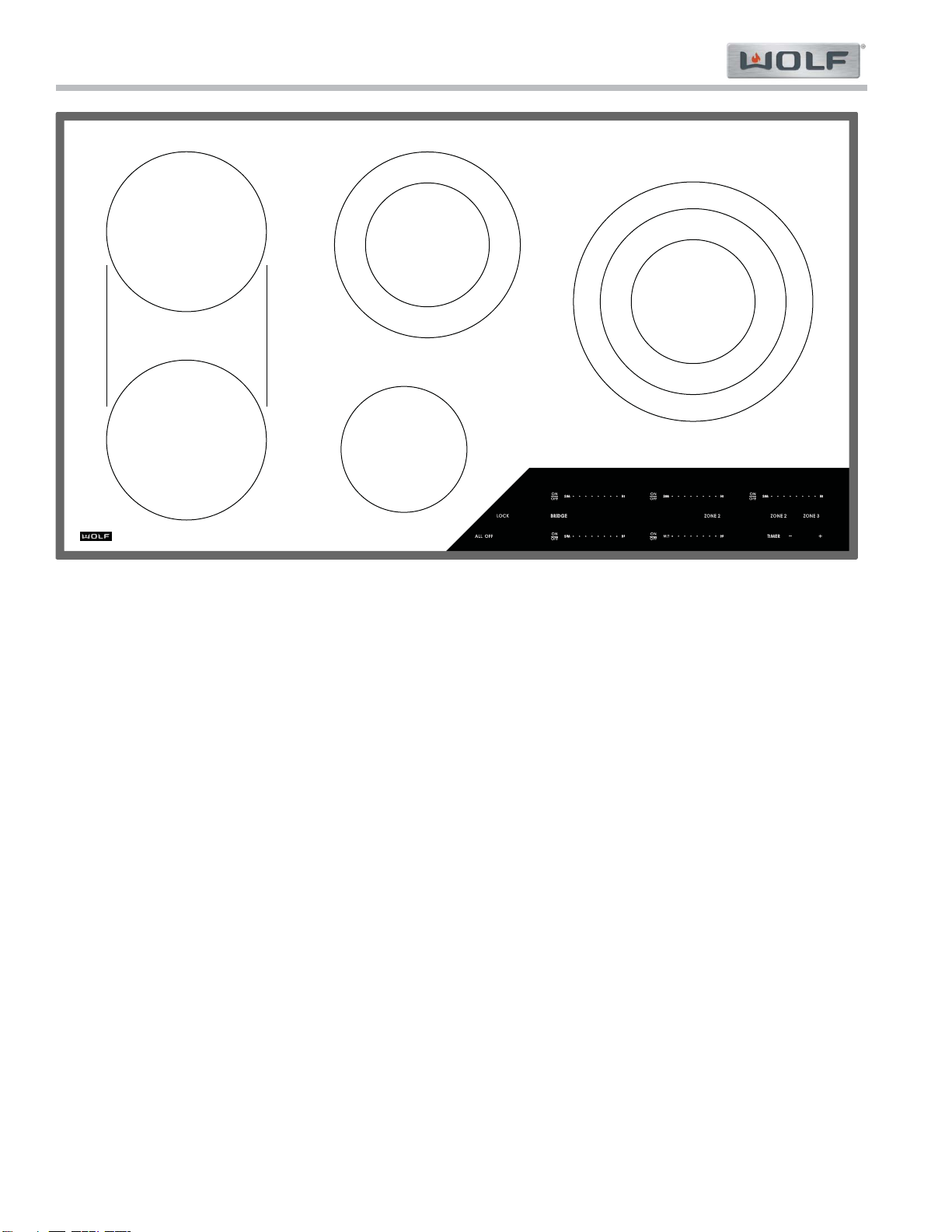
General Information
1-2
#826496 - Revision A - May, 2015
INTRODUCTION
This Technical Service Manual has been compiled to provide the most recent technical service information. This
information enables the service technician to troubleshoot and diagnose malfunctions, perform necessary repairs
and return the appliance to proper operational condition.
The service technician should read the complete instructions contained in this service manual before initiating any
repairs on a Wolf Appliance.
For installation information see Induction and Electric Cooktops Installation Guide available at http://www.subze-
ro-wolf.com/trade-resources/product-specifications.
For Use and Care information see Use & Care Guide: Induction Cooktops available at http://www.subzero-
wolf.com/trade-resources/product-specifications.
IMPORTANT SAFETY INFORMATION
Below are the Product Safety Labels used in this manu-
al. The "Signal Words" used are WARNING and
CAUTION.
Please note that these safety labels are placed in areas
where awareness of personal safety and product safety
should be taken and lists the precautions to be taken
when the signal word is observed.
This manual is designed to be used by Certified Service Personnel only. Wolf Appliance, Inc. assumes no
responsibility for any repairs made to Wolf appliances by anyone other than Certified Service Technicians.
INDICATES THAT HAZARDOUS OR UNSAFE
PRACTICES COULD RESULT IN SEVERE PERSON-
AL INJURY OR DEATH.
Indicates that hazardous or unsafe practices could
result in minor personal injury or product and/or
property damage
In addition, please pay attention to the signal word
“NOTE”, which highlights especially important informa-
tion within each section.
The information and images are the copyright property of Wolf Appliance, Inc., an affiliate of
Sub-Zero Group, Inc. Neither this manual nor any information or images contained herein may be copied or used in
whole or in part without the express written permission of Wolf Appliance, Inc., an affiliate of Sub-Zero Group, Inc. ©
Wolf Appliance, Inc., all rights reserved.
TECHNICAL ASSISTANCE
If you should have any questions regarding the appli-
ance and/or this manual, please contact:
Wolf Appliance, Inc.
ATTN: Service Department
P.O. Box 44988
Madison, WI 53744 - 4988
Customer Care
Phone #: (800) 332 - 9513
Facsimile #: (608) 441 - 5887
Technical Assistance
(For Technicians in Customer’s Homes Only)
Phone #: (800) 919 - 8324
Warranty Claims
Phone #: (800) 404 - 7820
Facsimile #: (608) 441 - 5886
Service Department e-mail Address:
Main Office Hours:
8:00 AM to 5:00 PM Central Time
Monday through Friday
(24/7 Phone Coverage)