Subzero WOLF CSO User manual

Page 2
SERVICE MANUAL INTRODUCTION
This technical service manual information assists with
troubleshooting and diagnosing malfunctions, completion of
repairs, and return of the product to proper operational
condition. Read the complete instructions contained within
before initiating any repairs.
This guide is intended for use by Factory Certified Service. Wolf
Appliance, Inc. recommends that repairs be performed by
Factory Certified Service only.
Warning and Caution product safety labels appear throughout
this manual. Product safety labels appear at the beginning of
some sections. Follow the instructions in the product safety
labels to avoid personal injury and/or product damage. The
sample safety labels explain the types of notices that appear in
this manual.
WARNING
States a hazard that may cause serious injury or
death if precautions are not followed.
CAUTION
Indicates minor injury or product damage may occur
if instructions are not followed.
IMPORTANT NOTE: Highlights especially important information.
TIP: Indicates additional, useful information.
Information and images contained herein are copyright of Wolf
Appliance, Inc. Neither this manual nor any information or
images contained herein may be copied or used in whole or in
part without the express written consent of Wolf Appliance, Inc.
©Wolf Appliance, Inc., all rights reserved.
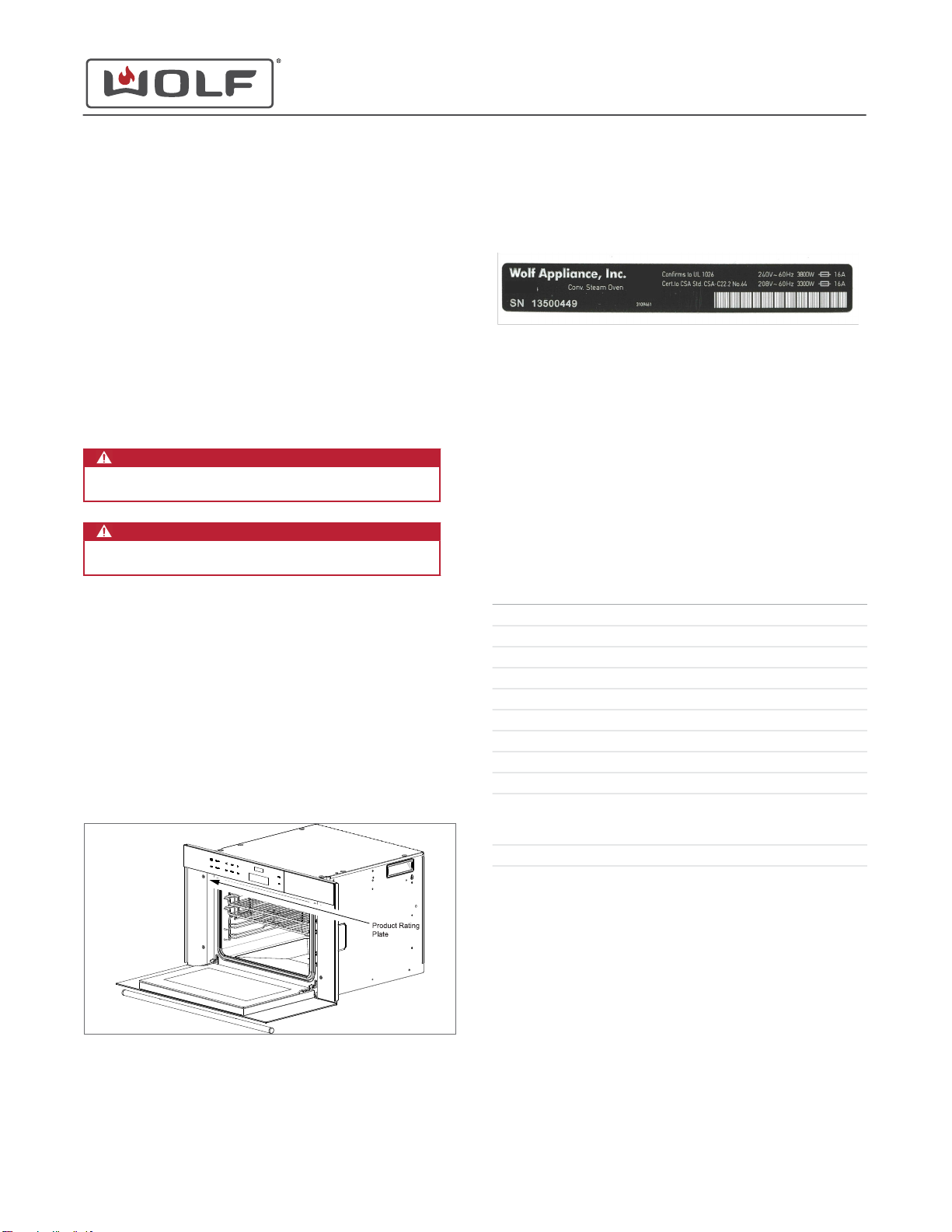
WOLF PRODUCT RATING PLATE INFORMATION
On the CSO, the rating plate with the serial number is located
on the left hand side trim inside the door.
Important information for each product is listed on the product
rating plate. Rating plates identify:
▪Model
▪Serial number
▪Electrical information, including current draw
CSO24TE/S
MODEL DESCRIPTIONS AND SALES ACCESSORIES
For more details on individual model descriptions and a listing
of all compatible sales accessories, see the
Sub-Zero
Distributor Price List
.
CSO MODEL KEY
Description Model Character
Convection Steam Oven CSO
Nominal Width 24" and 30"
Trim Style T Transitional
Trim Style P Professional
Trim Style C Contemporary
Matching Oven Trim E E Series Ovens
Matching Oven Trim M M Series Ovens
Metal Type /S for Stainless Steel
Metal Type /B for Black
Stainless Steel Handle Style /TH for Tubular Handles
/PH for Professional Handles
International Designation ICB
PRODUCT USE AND CARE AND INSTALLATION GUIDES
Product Use and Care Guides, Installation Guides, and other
product specifications are available in the
Product
Specifications and Manuals Library
.
CSO (SWS #13543126)
General Information
GENERAL INFORMATION
service.subzero.com
827703 REVA 02/2018 1

Page 3
UNIT WARRANTY
Product warranty is determined by the installation location and
the date of installation.
▪View product warranties at
http://service.subzero.com/
ClaimsAndOrderProcessing/Pages/WarrantyInfo
.
▪Warranties start on the day of product installation.
▪Search for warranty and service information by serial
number, customer last name, and address using Unit
History at
http://service.subzero.com/Tools/UnitHistory
.
CSO (SWS #13543126)
General Information
service.subzero.com
827703 REVA 02/2018 2

Page 4
DOOR REMOVAL
Remove the Door
1Open the door.
2Rotate the hinge retainer clip on each hinge forward until
the hinge retainer clip stops.
3Close the door until the door stops against the hinge
retainer clips.
4Grasp the door toward the top on each side.
5Push the top of the door toward closing, while rotating the
bottom of the door away from the unit.
6Remove the door from the unit.
DOOR INSTALLATION
Install the Door
1Holding the door at a 45° angle, insert the door hinges into
the hinge slots.
2Lower the oven door until the oven door stops.
3Pull the door to the open position.
4Rotate the hinge retainer clips on each hinge backward until
the hinge retainer clips stop.
5Test the door.
DOOR FRONT OR INNER DOOR REMOVAL
To remove the door front, first remove the door.
Remove the Door
1Open the door.
2Rotate the hinge retainer clip on each hinge forward until
the hinge retainer clip stops.
3Close the door until the door stops against the hinge
retainer clips.
4Grasp the door toward the top on each side.
5Push the top of the door toward closing, while rotating the
bottom of the door away from the unit.
6Remove the door from the unit.
Remove the Door Front or the Inner Door
1Place the door on a padded surface, handle side down.
2Use a T-10 Torx bit to remove the left and right inner door
mounting screws.
3Lift the bottom of the door front.
4Push the door front toward the top of the inner door.
5The door front and inner door are separated. Remove the
door front or the inner door.
CSO (SWS #13543126)
Cavity Component Removal and Installation
CAVITY COMPONENT REMOVAL AND INSTALLATION
service.subzero.com
827703 REVA 02/2018 3

Page 5
DOOR FRONT OR INNER DOOR INSTALLATION
Install the Door Front or Inner Door
1Place the upper and lower gaskets onto the inner door.
2Place the door front onto the inner door above the inner
door bracket.
3Lift the bottom of the door front above the lower bracket of
the inner door.
4Pull the door front down over the inner door bracket.
5Use a T-10 Torx bit to install the left and right inner door
mounting screws.
Install the Door
1Holding the door at a 45° angle, insert the door hinges into
the hinge slots.
2Lower the oven door until the oven door stops.
3Pull the door to the open position.
4Rotate the hinge retainer clips on each hinge backward until
the hinge retainer clips stop.
5Test the door.
DOOR HANDLE REMOVAL
To remove the door handle, first remove the door, then separate
the door front and the inner door.
Remove the Door
1Open the door.
2Rotate the hinge retainer clip on each hinge forward until
the hinge retainer clip stops.
3Close the door until the door stops against the hinge
retainer clips.
4Grasp the door toward the top on each side.
5Push the top of the door toward closing, while rotating the
bottom of the door away from the unit.
6Remove the door from the unit.
Remove the Door Front or the Inner Door
1Place the door on a padded surface, handle side down.
2Use a T-10 Torx bit to remove the left and right inner door
mounting screws.
3Lift the bottom of the door front.
4Push the door front toward the top of the inner door.
5The door front and inner door are separated. Remove the
door front or the inner door.
Remove the Door Handle
1Use a T-25 Torx bit to remove the handle mounting screws.
CSO (SWS #13543126)
Cavity Component Removal and Installation
service.subzero.com
827703 REVA 02/2018 4

Page 6
2Remove the handle and handle standoffs from the door
front.
DOOR HANDLE INSTALLATION
Install the Door Handle
1Place the door handle and handle standoffs onto the door
front.
2Use a T-25 Torx bit to install the handle mounting screws.
Install the Door Front or Inner Door
1Place the upper and lower gaskets onto the inner door.
2Place the door front onto the inner door above the inner
door bracket.
3Lift the bottom of the door front above the lower bracket of
the inner door.
4Pull the door front down over the inner door bracket.
5Use a T-10 Torx bit to install the left and right inner door
mounting screws.
Install the Door
1Holding the door at a 45° angle, insert the door hinges into
the hinge slots.
2Lower the oven door until the oven door stops.
3Pull the door to the open position.
4Rotate the hinge retainer clips on each hinge backward until
the hinge retainer clips stop.
5Test the door.
INTERMEDIATE DOOR GLASS REMOVAL
To remove the intermediate door glass, first remove the door,
then separate the door front and the inner door.
Remove the Door
1Open the door.
2Rotate the hinge retainer clip on each hinge forward until
the hinge retainer clip stops.
3Close the door until the door stops against the hinge
retainer clips.
4Grasp the door toward the top on each side.
5Push the top of the door toward closing, while rotating the
bottom of the door away from the unit.
6Remove the door from the unit.
Remove the Door Front or the Inner Door
1Place the door on a padded surface, handle side down.
2Use a T-10 Torx bit to remove the left and right inner door
mounting screws.
3Lift the bottom of the door front.
4Push the door front toward the top of the inner door.
CSO (SWS #13543126)
Cavity Component Removal and Installation
REMOVE THE DOOR HANDLE (continued)
service.subzero.com
827703 REVA 02/2018 5

Page 7
5The door front and inner door are separated. Remove the
door front or the inner door.
Remove the Intermediate Door Glass
1Use pliers to straighten the glass retainer tabs.
2Remove the intermediate door glass from the inner door.
3Remove the gasket if necessary.
INTERMEDIATE DOOR GLASS INSTALLATION
Install the Intermediate Door Glass
1Install the gasket if removed.
2Place the intermediate door glass on the inner door.
3Use pliers to bend the glass retainer tabs over the
intermediate door glass.
Install the Door Front or Inner Door
1Place the upper and lower gaskets onto the inner door.
2Place the door front onto the inner door above the inner
door bracket.
3Lift the bottom of the door front above the lower bracket of
the inner door.
4Pull the door front down over the inner door bracket.
5Use a T-10 Torx bit to install the left and right inner door
mounting screws.
Install the Door
1Holding the door at a 45° angle, insert the door hinges into
the hinge slots.
2Lower the oven door until the oven door stops.
3Pull the door to the open position.
4Rotate the hinge retainer clips on each hinge backward until
the hinge retainer clips stop.
5Test the door.
DOOR SEAL REMOVAL
Remove the Door Seal
1Open the oven door.
2Pull the door seal from the channel around the oven door.
DOOR SEAL INSTALLATION
Install the Door Seal
Insert the door seal in the channel around the oven door.
CSO (SWS #13543126)
Cavity Component Removal and Installation
REMOVE THE DOOR FRONT OR THE INNER DOOR (continued)
service.subzero.com
827703 REVA 02/2018 6

Page 8
RACK REMOVAL
Remove the Rack
Pull the rack forward out of the unit.
RACK INSTALLATION
Install the Rack
1Insert the rack between the rails of the rack guide.
2Push the rack into the oven.
RACK GUIDE REMOVAL
To remove a rack guide, first remove the racks.
Remove the Rack
Pull the rack forward out of the unit.
Remove the Rack Guide
1Remove the rack guide nut.
2Pull the front of the rack guide toward the center of the
oven.
3Pull the rack guide forward out of the unit.
RACK GUIDE INSTALLATION
Install the Rack Guide
1Insert the rack guide rails into the rear baffle.
2Place the indent in the rack guide over the rack guide stud.
3Install the rack guide nut.
Install the Rack
1Insert the rack between the rails of the rack guide.
2Push the rack into the oven.
FOOD PROBE COVER REMOVAL
To remove the probe cover, first remove the racks and the right-
hand rack guide.
CSO (SWS #13543126)
Cavity Component Removal and Installation
service.subzero.com
827703 REVA 02/2018 7

Page 9
Remove the Rack
Pull the rack forward out of the unit.
Remove the Rack Guide
1Remove the rack guide nut.
2Pull the front of the rack guide toward the center of the
oven.
3Pull the rack guide forward out of the unit.
Remove the Food Probe Cover
1Lift the food probe cover.
2Use an 11 mm socket to remove the food probe cover nut.
3Remove the food probe cover, nut, and food probe cover
seal from the unit.
FOOD PROBE COVER INSTALLATION
Install the Food Probe Cover
1Place the food probe seal onto the food probe cover.
2Place the food probe cover over the food probe switch
threads.
3Use an 11 mm socket to install the food probe nut.
Install the Rack Guide
1Insert the rack guide rails into the rear baffle.
2Place the indent in the rack guide over the rack guide stud.
3Install the rack guide nut.
Install the Rack
1Insert the rack between the rails of the rack guide.
2Push the rack into the oven.
HALOGEN LIGHT BULB REMOVAL
WARNING
Turn off the power to the product before starting this
procedure.
To remove the halogen light bulb, first remove the racks and the
left rack guide.
CSO (SWS #13543126)
Cavity Component Removal and Installation
service.subzero.com
827703 REVA 02/2018 8

Page 10
Remove the Rack
Pull the rack forward out of the unit.
Remove the Rack Guide
1Remove the rack guide nut.
2Pull the front of the rack guide toward the center of the
oven.
3Pull the rack guide forward out of the unit.
Remove the Halogen Light Bulb
1Use a T-20 Torx bit to remove the screws from the oven light
frame assembly.
2Remove the oven light frame assembly.
3Remove the oven light safety glass.
4Remove the oven light seal if required.
5Remove the halogen light bulb.
HALOGEN LIGHT BULB INSTALLATION
Install the Halogen Light Bulb
TIP: Use a cloth to install the halogen light bulb. Oil from
fingers shortens the life of the halogen light bulb.
1Insert the halogen light bulb into the socket.
2Install the oven light seal into the oven light frame assembly
if it was removed.
3Place the oven light safety glass onto the oven light seal.
4Place the oven light safety glass, oven light seal, and oven
light frame assembly over the light housing.
5Use a T-20 Torx bit to install the screws into the oven light
housing.
Install the Rack Guide
1Insert the rack guide rails into the rear baffle.
2Place the indent in the rack guide over the rack guide stud.
3Install the rack guide nut.
Install the Rack
1Insert the rack between the rails of the rack guide.
2Push the rack into the oven.
REAR BAFFLE REMOVAL
To remove the rear baffle, first remove the racks and rack
guides.
CSO (SWS #13543126)
Cavity Component Removal and Installation
service.subzero.com
827703 REVA 02/2018 9

Page 11
Remove the Rack
Pull the rack forward out of the unit.
Remove the Rack Guide
1Remove the rack guide nut.
2Pull the front of the rack guide toward the center of the
oven.
3Pull the rack guide forward out of the unit.
Remove the Rear Baffle
1Use a T-20 Torx bit to remove the screws from the rear
baffle.
2Remove the rear baffle from the unit.
REAR BAFFLE INSTALLATION
Install the Rear Baffle
1Place the rear baffle against the back wall of the oven
cavity.
2Use a T-20 Torx bit to install the screws into the rear baffle.
Install the Rack Guide
1Insert the rack guide rails into the rear baffle.
2Place the indent in the rack guide over the rack guide stud.
3Install the rack guide nut.
Install the Rack
1Insert the rack between the rails of the rack guide.
2Push the rack into the oven.
HOT AIR FAN BLADE REMOVAL
To remove the hot air fan blade, first remove the racks, rack
guides, and rear baffle.
CSO (SWS #13543126)
Cavity Component Removal and Installation
service.subzero.com
827703 REVA 02/2018 10

Page 12
Remove the Rack
Pull the rack forward out of the unit.
Remove the Rack Guide
1Remove the rack guide nut.
2Pull the front of the rack guide toward the center of the
oven.
3Pull the rack guide forward out of the unit.
Remove the Rear Baffle
1Use a T-20 Torx bit to remove the screws from the rear
baffle.
2Remove the rear baffle from the unit.
Remove the Hot Air Fan Blade
TIP: The hot air fan blade nut is reverse threaded.
1Use a 10 mm socket to remove the nut from the hot air fan
blade.
2Remove the washer and the hot air fan blade from the unit.
3The washer and C-clip behind the hot air fan blade does not
need to be removed unless the convection fan motor is
being removed.
HOT AIR FAN BLADE INSTALLATION
Install the Hot Air Fan Blade
1Install the C-clip and washer if they were removed for
replacement of the convection fan motor.
2Install the hot air fan blade.
3Install the washer.
TIP: The hot air fan blade nut is reverse-threaded.
CSO (SWS #13543126)
Cavity Component Removal and Installation
service.subzero.com
827703 REVA 02/2018 11

Page 13
4Use a 10 mm socket to install the nut onto the hot air fan
blade.
Install the Rear Baffle
1Place the rear baffle against the back wall of the oven
cavity.
2Use a T-20 Torx bit to install the screws into the rear baffle.
Install the Rack Guide
1Insert the rack guide rails into the rear baffle.
2Place the indent in the rack guide over the rack guide stud.
3Install the rack guide nut.
Install the Rack
1Insert the rack between the rails of the rack guide.
2Push the rack into the oven.
ELEMENT REMOVAL
WARNING
Turn off the power to the product before starting this
procedure.
To remove the element, first remove the racks, rack guides, and
rear baffle.
Remove the Rack
Pull the rack forward out of the unit.
Remove the Rack Guide
1Remove the rack guide nut.
2Pull the front of the rack guide toward the center of the
oven.
3Pull the rack guide forward out of the unit.
Remove the Rear Baffle
1Use a T-20 Torx bit to remove the screws from the rear
baffle.
2Remove the rear baffle from the unit.
Remove the Element
1Use a T-20 Torx bit to remove the screws and washer from
the element.
2Pull the element forward and disconnect the electrical wires.
3Remove the gasket seal from the element.
CSO (SWS #13543126)
Cavity Component Removal and Installation
INSTALL THE HOT AIR FAN BLADE (continued)
service.subzero.com
827703 REVA 02/2018 12

Page 14
4Remove the element form the unit.
ELEMENT INSTALLATION
Install the Element
1Install the gasket seal onto the element.
2Connect the electrical wires to the element.
3Install the element through the back wall of the oven cavity.
4Use a T-20 Torx bit to install the screws and washer into the
element.
Install the Rear Baffle
1Place the rear baffle against the back wall of the oven
cavity.
2Use a T-20 Torx bit to install the screws into the rear baffle.
Install the Rack Guide
1Insert the rack guide rails into the rear baffle.
2Place the indent in the rack guide over the rack guide stud.
3Install the rack guide nut.
Install the Rack
1Insert the rack between the rails of the rack guide.
2Push the rack into the oven.
CSO (SWS #13543126)
Cavity Component Removal and Installation
REMOVE THE ELEMENT (continued)
service.subzero.com
827703 REVA 02/2018 13

Page 15
WATER TANK REMOVAL
Remove the Water Tank
1Touch Water on the control panel.
2Remove the water tank from the unit.
WATER TANK INSTALLATION
Install the Water Tank Assembly
1Install the water tank into the unit.
2Push the water tank closed.
TOP PLATE REMOVAL
WARNING
Turn off the power to the product before starting this
procedure.
Remove the Top Plate
1Use a T-20 Torx bit to remove the screws from the top and
back of the unit.
2Remove the top plate from the unit.
TOP PLATE INSTALLATION
Install the Top Plate
1Place the top plate on the unit.
2Use a T-20 Torx bit to install the screws into the top plate.
DOOR SWITCH REMOVAL
To remove the door switch, first remove the top plate.
Remove the Top Plate
1Use a T-20 Torx bit to remove the screws from the top and
back of the unit.
2Remove the top plate from the unit.
Remove the Door Switch
1Disconnect the door switch electrical connector from the
control board.
CSO (SWS #13543126)
Top Component Removal and Installation
TOP COMPONENT REMOVAL AND INSTALLATION
service.subzero.com
827703 REVA 02/2018 14

Page 16
2Open the door switch bracket tab and remove the door
switch from the door switch bracket.
DOOR SWITCH INSTALLATION
Install the Door Switch
1Place the door switch in the door switch bracket.
2Connect the door switch connector to the control board.
Install the Top Plate
1Place the top plate on the unit.
2Use a T-20 Torx bit to install the screws into the top plate.
VALVE ASSEMBLY REMOVAL
The valve assembly includes the water valve, water tank
microswitch, water tank drive motor, and the water tank rail.
To remove the valve assembly, first remove the water tank and
the top plate.
Remove the Water Tank
1Touch Water on the control panel.
2Remove the water tank from the unit.
Remove the Top Plate
1Use a T-20 Torx bit to remove the screws from the top and
back of the unit.
2Remove the top plate from the unit.
Remove the Valve Assembly
1Remove the electrical connectors from the water tank
microswitch.
2Remove the electrical connectors from the water valve.
3Remove the ground wires.
4Remove the drive motor tab from the tank housing cover.
5Use a T-10 Torx bit to remove the screws from the valve
assembly.
CSO (SWS #13543126)
Top Component Removal and Installation
REMOVE THE DOOR SWITCH (continued)
service.subzero.com
827703 REVA 02/2018 15

Page 17
6Remove the valve assembly from the unit.
VALVE ASSEMBLY INSTALLATION
Install the Valve Assembly
1Place the valve assembly into the tank housing base.
2Use a T-10 Torx bit to install the screws into the valve
assembly.
3Install the drive motor tab into the notch in the tank housing
cover.
4Connect the ground wires.
5Connect the valve assembly electrical connectors.
6Connect the water tank microswitch electrical connectors.
Install the Top Plate
1Place the top plate on the unit.
2Use a T-20 Torx bit to install the screws into the top plate.
Install the Water Tank Assembly
1Install the water tank into the unit.
2Push the water tank closed.
TANK HOUSING COVER REMOVAL
To remove the tank housing cover, first remove the top plate.
Remove the Top Plate
1Use a T-20 Torx bit to remove the screws from the top and
back of the unit.
2Remove the top plate from the unit.
Remove the Tank Housing Cover
1Remove the wire guides from the tank housing cover.
2Use a T-10 Torx bit to remove the screws from the tank
housing cover.
3Remove the tank housing cover from the unit.
TANK HOUSING COVER INSTALLATION
Install the Tank Housing Cover
1Place the tank housing cover onto the tank housing base.
2Use a T-10 Torx bit to install the screws into the tank
housing cover.
3Install the wire harness clips onto the tank housing cover.
CSO (SWS #13543126)
Top Component Removal and Installation
REMOVE THE VALVE ASSEMBLY (continued)
service.subzero.com
827703 REVA 02/2018 16

Page 18
Install the Top Plate
1Place the top plate on the unit.
2Use a T-20 Torx bit to install the screws into the top plate.
TANK HOUSING BASE REMOVAL
To remove the tank housing base, first remove the water tank,
top plate, tank housing cover, and valve assembly.
Remove the Water Tank
1Touch Water on the control panel.
2Remove the water tank from the unit.
Remove the Top Plate
1Use a T-20 Torx bit to remove the screws from the top and
back of the unit.
2Remove the top plate from the unit.
Remove the Tank Housing Cover
1Remove the wire guides from the tank housing cover.
2Use a T-10 Torx bit to remove the screws from the tank
housing cover.
3Remove the tank housing cover from the unit.
Remove the Valve Assembly
1Remove the electrical connectors from the water tank
microswitch.
2Remove the electrical connectors from the water valve.
3Remove the ground wires.
4Remove the drive motor tab from the tank housing cover.
5Use a T-10 Torx bit to remove the screws from the valve
assembly.
6Remove the valve assembly from the unit.
Remove the Tank Housing Base
1Use a T-20 Torx bit to remove the screws from the side of
the tank housing base.
2Push the tank housing base forward out of the control
panel.
CSO (SWS #13543126)
Top Component Removal and Installation
service.subzero.com
827703 REVA 02/2018 17

Page 19
3Remove the tank housing base from the unit.
TANK HOUSING BASE INSTALLATION
Install the Tank Housing Base
1Insert the tank housing base into the control panel.
2Use a T-20 Torx bit to install the screws into the tank
housing base.
Install the Valve Assembly
1Place the valve assembly into the tank housing base.
2Use a T-10 Torx bit to install the screws into the valve
assembly.
3Install the drive motor tab into the notch in the tank housing
cover.
4Connect the ground wires.
5Connect the valve assembly electrical connectors.
6Connect the water tank microswitch electrical connectors.
Install the Tank Housing Cover
1Place the tank housing cover onto the tank housing base.
2Use a T-10 Torx bit to install the screws into the tank
housing cover.
3Install the wire harness clips onto the tank housing cover.
Install the Top Plate
1Place the top plate on the unit.
2Use a T-20 Torx bit to install the screws into the top plate.
Install the Water Tank Assembly
1Install the water tank into the unit.
2Push the water tank closed.
CONTROL BOARD REMOVAL
To remove the control board, first remove the top plate.
Remove the Top Plate
1Use a T-20 Torx bit to remove the screws from the top and
back of the unit.
2Remove the top plate from the unit.
Remove the Control Board
1Open the locks on the ribbon cable connectors, and remove
the ribbon cables from the control board.
2Disconnect the electrical connectors from the control board.
3Open the control board bracket tabs along the top of the
control board.
CSO (SWS #13543126)
Top Component Removal and Installation
REMOVE THE TANK HOUSING BASE (continued)
service.subzero.com
827703 REVA 02/2018 18

Page 20
4Remove the control board from the unit.
CONTROL BOARD INSTALLATION
Install the Control Board
1Place the bottom of the control board into the control board
bracket supports.
2Push the top of the control board into the control board
bracket.
3Insert the ribbon cables into the ribbon cable connectors
and lock the ribbon cable connector.
4Connect the electrical connectors to the control board.
Install the Top Plate
1Place the top plate on the unit.
2Use a T-20 Torx bit to install the screws into the top plate.
DISPLAY REMOVAL
To remove the display, first remove the top plate and the control
board.
Remove the Top Plate
1Use a T-20 Torx bit to remove the screws from the top and
back of the unit.
2Remove the top plate from the unit.
Remove the Control Board
1Open the locks on the ribbon cable connectors, and remove
the ribbon cables from the control board.
2Disconnect the electrical connectors from the control board.
3Open the control board bracket tabs along the top of the
control board.
CSO (SWS #13543126)
Top Component Removal and Installation
REMOVE THE CONTROL BOARD (continued)
service.subzero.com
827703 REVA 02/2018 19
Table of contents
Popular Convection Oven manuals by other brands

turbofan
turbofan E20M Series Installation and operation manual

Onida
Onida POWER CONVECTION28L user manual

Fagor
Fagor HALOGEN TABLETOP OVEN User's manual & recipe booklet

Rival
Rival CO606 owner's guide

Suzanne Somers
Suzanne Somers Somersize manual

Mainstreet Equipment
Mainstreet Equipment 541CG1N user manual

Equipex
Equipex SODIR FC-33 Operation manual

Vollrath
Vollrath Proton 40702 Operating and safety instructions

Land
Land ECOD-AT Assembly, installation and operation instructions

Comelec
Comelec HO 2507 C user manual

Zanussi
Zanussi EasyPlus 239004 Brochure & specs

Moffat
Moffat Bakbar Turbofan E35 Specifications