Subzero WOLF SPO User manual

Page 2
SERVICE MANUAL INTRODUCTION
This service manual helps with troubleshooting and diagnosing
malfunctions, completion of repairs, and return of the product to
proper operating condition. Read the complete instructions
contained within before initiating any repairs.
This guide is intended for use by Factory Certified Service. Wolf
Appliance, Inc. recommends that only Factory Certified Service
companies do repairs.
Warning and Caution product safety labels appear throughout
this manual. Product safety labels appear at the beginning of
some sections. Follow the instructions in the product safety
labels to avoid personal injury and/or product damage. The
sample safety labels explain the types of notices that appear in
this manual.
WARNING
States a hazard that may cause serious injury or
death if precautions are not followed.
CAUTION
Indicates minor injury or product damage may occur
if precautions are not followed.
IMPORTANT NOTE: Highlights especially important information.
TIP: Indicates additional, useful information.
Information and images contained herein are copyright of Wolf
Appliance, Inc. Neither this manual nor any information or
images contained herein may be copied or used in whole or in
part without the express written consent of Wolf Appliance, Inc.
©Wolf Appliance, Inc., all rights reserved.
WOLF PRODUCT RATING PLATE INFORMATION
For Speed Ovens, the product rating plate is on the lower trim
inside the door.
Important information for each product is listed on the product
rating plate. Rating plates identify:
▪Model
▪Serial number
▪Electrical information
MODEL DESCRIPTIONS AND SALES ACCESSORIES
For more details on individual model descriptions and a listing
of all compatible sales accessories, see the
Wolf Distributor
Price List
.
SPEED OVEN MODEL KEY
Model Character Description
ICB International Designation
SPO Speed Oven
24 or 30 Width in Inches
T Transitional Trim Style
P Professional Trim Style
C Contemporary Trim Style
E E Series Oven Style
M M Series Oven Style
/S Stainless Steel Finish
/B Black Glass Finish
/TH Tubular Handles
/PH Professional Handles
PRODUCT USE AND CARE AND INSTALLATION GUIDES
Product use and care guides, installation guides, and other
product specifications are available in the
Product
Specifications and Manuals Library
.
UNIT WARRANTY
Product warranty is determined by the installation location and
the date of installation.
▪View product warranties at
http://service.subzero.com/
ClaimsAndOrderProcessing/Pages/WarrantyInfo
.
▪Warranties start on the day of product installation.
▪Search for warranty and service information by serial
number, customer last name, and address using Unit
History at
http://service.subzero.com/Tools/UnitHistory
.
Speed Oven
General Information
GENERAL INFORMATION
service.subzero.com
828422 REV. A 03/2019 1

Page 3
COMPONENTS
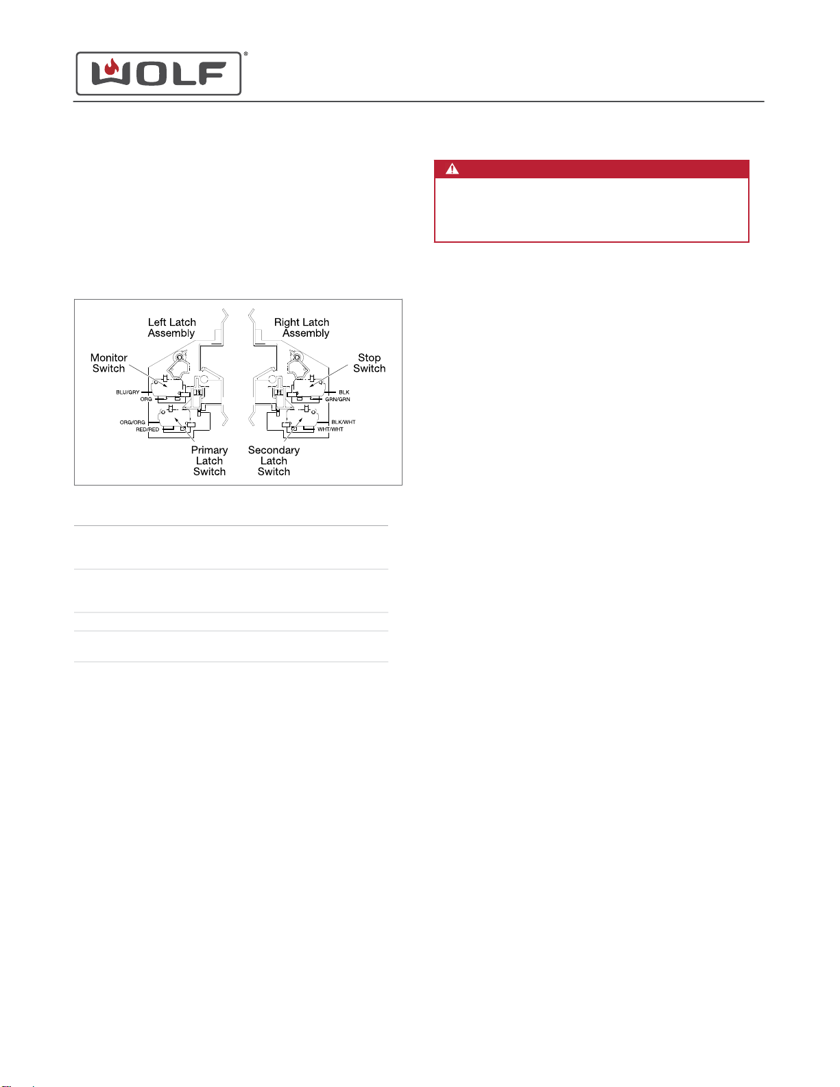
Door Switches and Interlocks
The appliance's safety interlock system includes four switches:
primary and secondary interlock switches, a monitor switch,
and a stop switch. Closing the door operates the switches.
Switch Contact Type Door Closed Door Open
(No Cooking)
Primary
interlock
switch
COM-NO Closed Open
Secondary
interlock
switch
COM-NO Closed Open
Stop switch COM-NO Closed Open
Monitor
switch COM-NC Open Closed
Opening the primary interlock switch opens the circuits to the
power transformer and turntable motor. The oven lamp and
display are controlled electronically. They stay on even if the
oven door is opened after the cooking cycle has been
interrupted.
The monitor switch is mechanically controlled by the oven door
and monitors the operation of the primary interlock switch:
▪When the oven door opens during or after the cooking
cycle, the monitor switch and stop switch must open their
contacts (COM-NO) first. After that, the contacts (COM-NC)
of the monitor switch can close.
▪When the oven door closes, the contacts (COM-NC) of the
monitor switch must be opened first. The contacts (COM-
NO) of the monitored latch switch and stop switch are
closed after.
▪If the oven door opens and the monitor switch stays closed,
the 20 A fuse will blow because the closed monitor switch
causes a short circuit.
CAUTION
Before replacing a blown 20 A fuse,
test the primary
interlock switch and monitor switch
for proper
operation. To verify correct operation,
adjust
and
check
the latch alignment.
The 20 Amp Fuse
The 20 A fuse is located on the rear of the unit on the noise
filter. It blows to prevent an electric shock or fire hazard when
the main wire harness or electrical components are shorted,
including the magnetron, capacitor, rectifier assembly, high-
voltage wire harness, or transformer secondary winding.
The Oven Thermal Cutout
The thermal cutout above the oven cavity can prevent damage
to the oven if items in the oven catch fire, whether due to
improper settings or control unit failure.
Under normal operation, the oven thermal cutout is closed.
However, when abnormally high temperatures occur within the
oven cavity, the oven thermal cutout will open at ~293°F,
causing the oven to shut down. It is necessary to replace a
tripped or defective thermal cutout with a new one.
The Magnetron Thermal Cutout
A thermal cutout protects the magnetron against overheating
due to problems with the fan motor or ventilation openings.
If the temperature rises higher than 293°F, the thermal cutout
TC02 will open. Line voltage supply to the high-voltage
transformer will stop, and the magnetron will stop operating. It
is necessary to replace a tripped or defective thermal cutout
with a new one.
The Transformer
During microwave cooking, the primary winding of the power
transformer receives line voltage. The filament winding provides
3.3 VAC, and the secondary winding provides about 2000 VAC
on. A rectifier circuit uses the 2000 VAC to provide the
magnetron with about 4000 VDC.
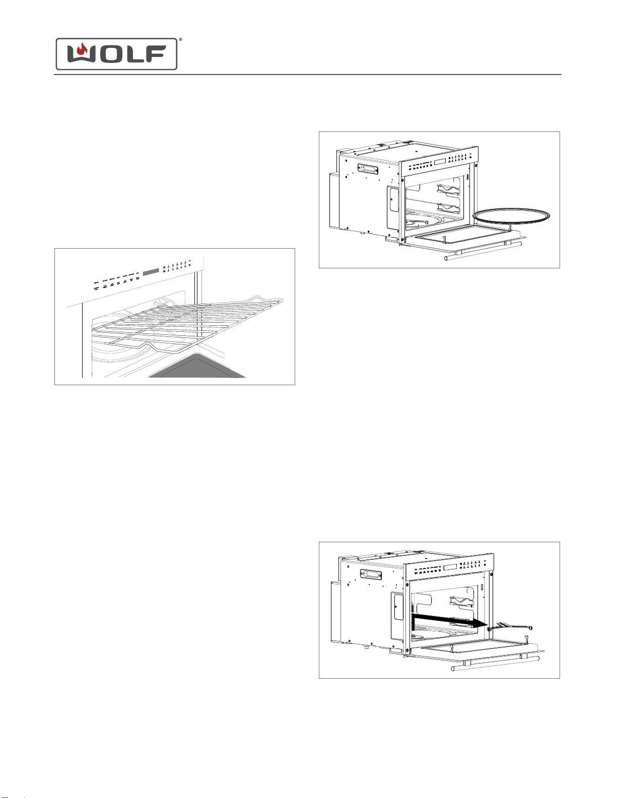
The Turntable Motor
The turntable motor drives the turntable roller assembly to
rotate the turntable.
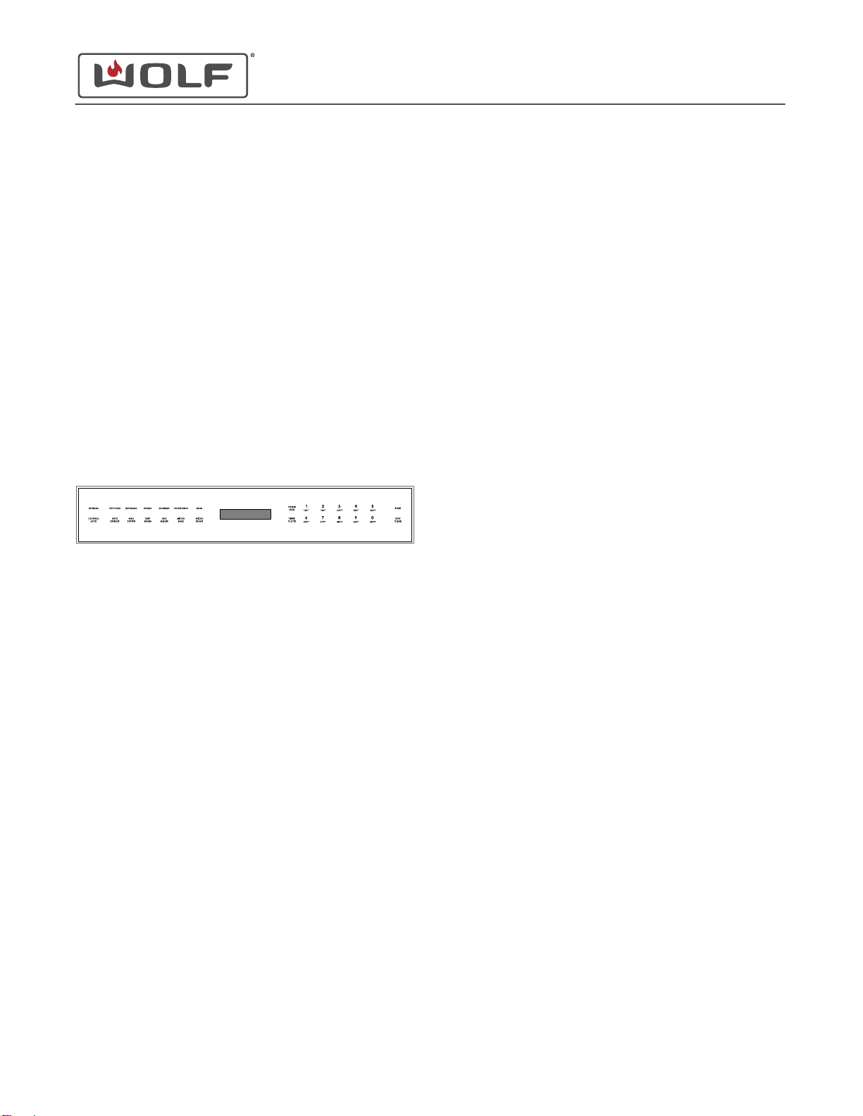
Speed Oven
Controls and Operation
CONTROLS AND OPERATION
service.subzero.com
828422 REV. A 03/2019 2

Page 4
The Cooling Fan Motor
The cooling fan motor turns the blades that draw in external
cool air. This cool air goes around the air vanes surrounding the
magnetron, cooling it. This air also flows through the oven
cavity to remove steam and vapors given off from the heating
foods. It then leaves the oven through the exhaust air vents at
the front of the oven cavity.
The Noise Filter
The noise filter prevents radio frequency interference that might
flow back through the power circuit.
THE CONTROL PANEL
The control panel features touch controls and an interactive
visual display.
Control Lock
The Control Lock feature prevents unwanted oven operation.
Turn On Control Lock
Touch Control Lock, then touch Start.
"LOCK ON" appears on the control panel display.
Turn Off Control Lock
Touch Control Lock, then touch Start.
"LOCK OFF" appears on the control panel display.
The Clock
It is necessary to set the clock prior to use and after a power
outage.
Set the Clock
1Touch Stop/Clear.
2Touch Timer/Clock once for 12-hour mode or twice for 24-
hour mode.
3Use the number pads to enter the time of day, then touch
Start.
The Timer
The timer has a maximum duration of 99 minutes and 99
seconds. After setting the timer, the countdown appears on the
control panel display. The oven chimes, and "END" appears on
the display when complete.
Set the Timer
1Touch Timer/Clock.
2Use the number pads to enter the timer duration.
3Touch Start to begin.
4Touch Stop/Clear to cancel.
SETTINGS
The Settings feature allows the user to select individual
preferences. It is necessary to reset the preferences after a
power outage.
Touch 1 on the control panel to toggle up or 6 to toggle down to
select preferences.
Audible Signals
An audible signal chimes with every touch and upon cook time
and timer completion.
Turn On Audible Signals
1Touch Settings.
2Touch 1.
3Touch Start.
"SOUND ON" appears on the control panel display.
Turn Off Audible Signals
1Touch Settings.
2Touch 6.
3Touch Start.
"SOUND OFF" appears on the control panel display.
Speed Oven
Controls and Operation
service.subzero.com
828422 REV. A 03/2019 3

Page 5
The Cook Time Completion Reminder
Upon completion, the oven chimes every ten seconds for the
first minute; then every three minutes (for one hour) until the
user touches Stop/Clear.
Turn On the Cook Time Completion Reminder
1Touch Settings twice.
2Touch 1.
3Touch Start.
"REMIND SIGNAL ON" appears on the control panel
display.
Turn Off the Cook Time Completion Reminder
1Touch Settings twice.
2Touch 6.
3Touch Start.
"REMIND SIGNAL OFF" appears on the control panel
display.
The Weight Unit of Measure
For cooking modes that require weight, the user can change the
default unit of measure between pounds and kilograms.
Change the Unit of Measure to Pounds
1Touch Settings three times.
2Touch 1.
3Touch Start.
"LBS SET" appears on the control panel display.
Change the Unit of Measure to Kilograms
1Touch Settings three times.
2Touch 6.
3Touch Start.
"KGS SET" appears on the control panel display.
Restore Factory Settings
1Touch Settings four times.
2Touch Start.
"FACTORY SETTINGS RESTORED" appears on the control
panel display.
Demonstration Mode
Demonstration mode is typically used in appliance showrooms.
It is a mode that demonstrates operation of the oven, but
without heating and with accelerated times.
Enter Demonstration Mode
1Touch Settings five times.
2Touch 1.
3Touch Start.
"DEMO ON" appears on the control panel display. "DEMO"
stays on the display.
Exit Demonstration Mode
1Touch Settings five times.
2Touch 6.
3Touch Start.
"DEMO OFF" appears on the control panel display.
MANUAL COOKING
Manual Power Levels
The speed oven has ten preset power levels.
Cook with Manual Power Levels
1Use the number pads to enter the desired cook time.
Speed Oven
Controls and Operation
service.subzero.com
828422 REV. A 03/2019 4

Page 6
2The default power level is 100%. To cook manually at a
power level less than 100%, touch Power Level and use the
number pads to select the desired power level.
Power Level Range Level
(default) High 100%
9 90%
8 80%
7 Medium High 70%
6 60%
5 Medium 50%
4 40%
3Medium Low |
Defrost 30%
2 20%
1 Low 10%
3Touch Start.
The oven chimes and "END" appears on the control panel
display when complete.
Multiple Sequence Cooking
The speed oven can be programmed for up to four automatic
cooking sequences, switching between modes, temperatures,
and power levels automatically (for example, start at 100%,
then switch to 50% power).
Use Multiple Sequence Cooking
1Touch Power Level and enter the desired power level for the
first cooking sequence (for 100%, touch Power Level a
second time), then use the number pads to enter the
desired cook time.
2Touch Power Level, then touch 5, then use the number
pads to enter a second cook time.
3Repeat if desired for a third and fourth cooking sequence.
4Touch Start.
The Add Minute Feature
The Add Minute feature cooks for one minute at 100% by
touching Add Minute. Touch multiple times to increase the cook
time. Each touch increases the cook time by one minute.
This feature cannot be used with Convection mode or Sensor
Cooking.
The Keep Warm Feature
The Keep Warm feature will keep food warm for up to 90
minutes.
Use the Keep Warm Feature
1Touch Keep Warm.
2Use the number pads to enter the desired keep warm time.
3Touch Start.
4Touch Stop/Clear to cancel.
The Popcorn Feature
The Popcorn feature has two options. Follow the directions on
the control panel display to select the desired option. Use only
popcorn packaged for microwave ovens.
Use the Popcorn Feature
1Touch Popcorn once for regular size packages or twice for
snack-size packages.
2Touch Start.
The Beverage Feature
The Beverage feature will reheat a beverage or prepare hot
water for coffee or tea.
Use the Beverage Feature
1Touch Beverage.
2Set the options:
▪To reheat beverage: Touch 1, then touch 1 or 6 to
select the amount in 1/2cup increments, up to 2 cups.
▪For hot water: Touch 2, then touch 1 or 6 to select
the amount in 1 cup increments, up to 6 cups.
3Touch Start.
The Melt/Soften Feature
The Melt/Soften feature will melt butter or chocolate and soften
cream cheese or butter.
Use the Melt/Soften Feature
1Touch Melt/Soften.
Speed Oven
Controls and Operation
COOK WITH MANUAL POWER LEVELS (continued)
service.subzero.com
828422 REV. A 03/2019 5

Page 7
2Set the options:
▪Melt butter: Touch 1, then touch 1 once for 2
tablespoons or twice for 1/2cup.
▪Melt chocolate: Touch 2.
▪Soften cream cheese: Touch 3.
▪Soften butter: Touch 4.
3Touch Start.
The Convection Feature
During convection cooking, hot air is circulated throughout the
oven to brown and crisp foods quickly and evenly. To view the
set temperature during cooking, touch Convection.
Use the Manual Convection Feature
1Touch Convection. If a temperature other than preset is
desired, touch Convection again, then use the number pads
to enter the temperature (for example, 6 for 350°F).
2Touch Start to begin preheat.
3When preheat is complete, add food, enter the desired cook
time, and touch Start.
The Broil Feature
The Broil feature uses elements in the top of the oven cavity to
provide direct heat to the top of foods for browning. Depending
on the food, the high or low riser should be used on the
turntable for best results.
Use the Broil Feature
1Touch Broil.
2Use the number pads to select the desired time.
3Touch Start.
Combination Cooking: Micro Bake and Micro Roast
The speed oven has two preset settings that make it easy to
cook with both convection heat and microwave automatically.
Microwave-safe or oven-safe bakeware may be used. With the
exception of those foods that cook best by convection cooking
alone, most foods are well suited to combination cooking using
either Micro Bake or Micro Roast.
The temperatures, which range from 100°F to 450°F, can be
changed. However, the power level cannot.
COMBINATION COOKING
Setting Temperature Power
Micro Bake 325°F 10%
Micro Roast 300°F 30%
Use Combination Cooking
1Touch Micro Bake or Micro Roast. If a temperature other
than the preset is desired, touch Micro Bake or Micro Roast
again, then use the number pads to enter the temperature
(for example, 6 for 350°F).
2Touch Start to begin preheat.
3When preheat is complete, add food, enter the desired cook
time, and touch Start.
The Auto Defrost Feature
The Auto Defrost feature uses preset settings to defrost select
food items.
Use the Auto Defrost Feature
1Touch Auto Defrost, then use the number pads to select the
desired food (for example, 3 for boneless poultry).
2Use the number pads to enter the weight.
3Touch Start.
After a period of time, the oven will stop so the food can be
checked.
4Open the door, and turn the food over.
5Repeat until defrost is complete.
Speed Oven
Controls and Operation
USE THE MELT/SOFTEN FEATURE (continued)
service.subzero.com
828422 REV. A 03/2019 6

Page 8
Auto Defrost Guide
Number Food Amount Instructions
1Ground
Meat
1/2- 2 lb
Remove any thawed
pieces after each audible
signal. Let stand for 5 -
10 minutes, covered.
2Steaks,
Chops
1/2- 3 lb
After each audible signal,
rearrange. If there are
warm or thawed portions,
shield with small flat
pieces of aluminum foil.
Remove any defrosted
meat. Let stand for 10 -
15 minutes, covered.
3Boneless
Poultry
1/2- 2 lb
After each audible signal,
rearrange. If there are
warm or thawed portions,
shield with small flat
pieces of aluminum foil.
Remove any defrosted
meat. Let stand for 10 -
15 minutes, covered.
4Bone-in
Poultry
1/2- 3 lb
After each audible signal,
rearrange. If there are
warm or thawed portions,
shield with small flat
pieces of aluminum foil.
Remove any defrosted
meat. Let stand for 10 -
15 minutes, covered.
5Roast 2 - 4 lb
Start defrosting with the
fat side down. After each
audible signal, turn over
and shield warm areas
with aluminum foil. Let
stand for 30 - 60 minutes,
covered.
SENSOR COOKING
The Gourmet Feature
The Gourmet feature detects moisture and humidity from food
as it heats and automatically adjusts the cook time and power
level. Fresh vegetables and poultry have two options. Follow
directions on the control panel display to select the desired
option.
Use the Gourmet Feature
1Touch Gourmet, then use the number pads to select the
desired food (for example, 5 for baked potatoes).
2Touch Start.
The Reheat Feature
The Reheat feature uses a sensor to detect moisture and
humidity from food as it reheats, and automatically adjusts the
cook time and power level.
Use the Reheat Feature
1Touch Reheat.
2Touch Start.
Speed Oven
Controls and Operation
service.subzero.com
828422 REV. A 03/2019 7

Page 9
OVEN RACK REMOVAL
Remove the Oven Rack
1Open the door.
2Slide the rack forward in the rack guides.
3Angle the front of the rack upward.
4Pull the rack forward and upward to clear the rack stops.
OVEN RACK INSTALLATION
Insert the Oven Rack
1Tilt the front of the rack upward, and insert the back of the
rack into the rack guides.
2Slide the rack back, and angle the front of the rack
downward to clear the rack stops.
3Continue to slide the rack back until completely inside the
oven.
DISH REMOVAL
To remove the dish, first remove:
1
Oven racks
Remove the Dish
1Lift the dish upward from the roller assembly.
2Remove the dish from then unit.
DISH INSTALLATION
Install the Dish
Place the dish into the unit so that it is centered on the roller
assembly.
ROLLER ASSEMBLY REMOVAL
To remove the roller assembly, first remove:
1
Oven racks
2
Turntable
Remove the Roller Assembly
1Lift the roller assembly upward.
2Remove the roller assembly from the unit.
Speed Oven
Cavity Component Removal and Installation
CAVITY COMPONENT REMOVAL AND INSTALLATION
service.subzero.com
828422 REV. A 03/2019 8

Page 10
ROLLER ASSEMBLY INSTALLATION
Install the Roller Assembly
Place the roller assembly onto the turntable coupler.
Speed Oven
Cavity Component Removal and Installation
service.subzero.com
828422 REV. A 03/2019 9

Page 11
CHOKE COVER SEAL REMOVAL
To remove the choke cover seal, first open the door.
Remove the Choke Cover Seal
1Use a putty knife or plastic knife to pry the choke cover seal
from between the choke cover and the door panel. Start
from any corner.
2Remove the choke cover seal.
CHOKE COVER SEAL INSTALLATION
Install the Choke Cover Seal
Press the choke cover seal into the groove between the
choke cover and the door panel.
TIP: The seal has a wide side and a narrow side. When
installing, make sure the wide side faces the oven cavity interior.
CHOKE COVER REMOVAL
To remove the choke cover, first remove:
1
Choke cover seal
Remove the Choke Cover
1Beginning on one of the short sides, press the choke cover
inward toward the center of the door to release one of the
clips.
2Work around the choke cover, using a putty knife or plastic
knife to reach under the choke cover and press in the clips.
3Remove the choke cover.
CHOKE COVER INSTALLATION
Install the Choke Cover
1Place the choke cover onto the door so that the choke
cover clips attach to the door panel.
TIP: Make sure the clips are installed so that their smooth sides
face away from the choke cover and the ends with the large
tabs face the door.
2Check that the door latches operate smoothly, and that the
door closes properly.
DOOR PANEL REMOVAL
To remove the door panel, first remove:
1
Choke cover seal
2
Choke cover
Remove the Door Panel
1Place a suitable weight on the open door to hold it open.
Speed Oven
Door Component Removal and Installation
DOOR COMPONENT REMOVAL AND INSTALLATION
service.subzero.com
828422 REV. A 03/2019 10

Page 12
2Support the door panel from below, and use a T-10 Torx bit
to remove the screws holding the door panel to the door.
3Remove the door panel from the unit.
DOOR PANEL INSTALLATION
Install the Door Panel
1With a suitable weight on the door to hold it open, position
the door panel under the door.
TIP: Support the door panel from below.
2Use a T-10 Torx bit to install the screws holding the door
panel to the door.
3Remove the weight from the door.
DOOR HANDLE REMOVAL
To remove the door handle, first remove:
1
Choke cover seal
2
Choke cover
Remove the Door Handle
1Use a T-20 Torx bit to remove the screws from the door
handle.
2Remove the door handle from the unit.
TIP: Be careful not to lose the small washers between the door
handle and door.
DOOR HANDLE INSTALLATION
Install the Door Handle
1Place the door handle over the holes in the door.
TIP: Make sure to include the small washers between the door
handle and door.
2Use a T-20 Torx bit to install the door handle screws.
CAUTION
Be careful not to overtighten the screws, which could
damage the door panel.
DOOR REMOVAL
The door is removed from underneath.
To remove the door, first
uninstall the unit
or pull it forward three
inches. Then, remove:
1
Air intake trim
Remove the Door
1Open the door.
2From underneath, use a T-20 Torx bit to remove the screws
from the hinge covers.
Speed Oven
Door Component Removal and Installation
REMOVE THE DOOR PANEL (continued)
service.subzero.com
828422 REV. A 03/2019 11

Page 13
3Remove the door from the unit.
DOOR INSTALLATION
Install the Door
1With the door hinges set to a 90° angle, slide the door into
the unit so that the hinges enter the openings on the bottom
of the unit and the door sits over the cavity. The door
latches should engage, holding the door onto the unit.
2Use a T-20 Torx bit to install the screws into the hinge
covers.
Adjust the Door Latch Microswitches
1Open the door, and insert a .5 mm shim.
2Close the door, with the shim still in position.
3With the door closed, push up on the bottom of the latch
assembly and use a T-20 Torx bit to tighten the screw.
Check the Door Latch Microswitch Adjustment
1With a .5 mm shim in place in the door, visually confirm
operation of the latches by opening and closing the door.
▪When the door is open, both microswitches should be
disengaged.
▪When the door is closed, both microswitches should
be engaged.
Speed Oven
Door Component Removal and Installation
REMOVE THE DOOR (continued)
service.subzero.com
828422 REV. A 03/2019 12

Page 14
2Remove the .5 mm shim.
Speed Oven
Door Component Removal and Installation
CHECK THE DOOR LATCH MICROSWITCH ADJUSTMENT (continued)
service.subzero.com
828422 REV. A 03/2019 13

Page 15
AIR INTAKE TRIM REMOVAL
To remove the control cover, first
uninstall the unit
or pull it
forward three inches.
Remove the Air Intake Trim
1Use a T-20 Security Torx bit to remove the screws from the
air intake trim.
2Remove the air intake trim from the unit.
AIR INTAKE TRIM INSTALLATION
Install the Air Intake Trim
1Place the air intake trim onto the unit.
2Use a T-20 Security Torx bit to install the screws into the air
intake trim.
UNIT HANDLE REMOVAL
To remove the unit handle, first
uninstall the unit
.
Remove the Unit Handle
1Use a T-20 Security Torx bit to remove the screws on the
sides of the unit handle.
2Remove the unit handle from the unit cover.
UNIT HANDLE INSTALLATION
Install the Unit Handle
1Insert the unit handle into the unit cover.
2Use a T-20 Security Torx bit to install the screws on the
sides of the unit handle.
LATCH COVER REMOVAL
To remove the latch cover, first
uninstall the unit
.
Remove the Door Latch Cover
1Use a T-20 Security Torx bit to remove the latch cover
screw.
2Remove the latch cover from the unit.
Speed Oven
External Component Removal and Installation
EXTERNAL COMPONENT REMOVAL AND INSTALLATION
service.subzero.com
828422 REV. A 03/2019 14

Page 16
LATCH COVER INSTALLATION
Install the Door Latch Cover
1Place the latch cover onto the unit.
2Use a T-20 Security Torx bit to install the latch cover screw.
LATCH MICROSWITCH REMOVAL
WARNING
Turn off the power to the product before starting this
procedure.
To remove the latch microswitch, first
uninstall the unit
. Then,
remove:
1
Latch cover
Remove the Door Latch Microswitch
1Disconnect the latch microswitch wire connectors.
2Use a T-20 Torx bit to remove the screw that secures the
latch hook assembly to the oven cavity.
3Slide the latch hook assembly upward, and remove it.
4Press the tab below the latch microswitch to be removed.
5Rotate the latch microswitch counterclockwise until it can
be removed from the stud on the latch assembly.
6Remove the latch microswitch from the unit.
LATCH MICROSWITCH INSTALLATION
Install the Door Latch Microswitch
1Place the latch microswitch onto the stud in the latch
assembly.
2Rotate the latch microswitch clockwise until it clicks under
the tab.
3Place the latch hook assembly into the latch assembly, and
press it downward.
4Use a T-20 Torx bit to install the screw that secures the
latch hook assembly to the oven cavity.
5Connect the latch microswitch wire connectors.
TURNTABLE MOTOR COVER REMOVAL
To remove the turntable motor cover, first
uninstall the unit
from
the opening and set the unit on its back.
Remove the Turntable Motor Cover
1Use a T-20 Security Torx bit to remove the screws from the
turntable motor cover.
2Remove the turntable motor cover from the unit.
TURNTABLE MOTOR COVER INSTALLATION
Install the Turntable Motor Cover
1Place the turntable motor cover onto the unit.
2Use a T-20 Security Torx bit to install the turntable motor
cover screws.
Speed Oven
External Component Removal and Installation
service.subzero.com
828422 REV. A 03/2019 15

Page 17
TURNTABLE MOTOR REMOVAL
To remove the turntable motor, first
uninstall the unit
from the
opening and set the unit on its back. Then, remove:
1
Turntable motor cover
Remove the Turntable Motor
1Disconnect the turntable motor wire connector.
2Use a T-20 Torx bit to remove the turntable motor screws.
3Remove the turntable motor from the unit.
TURNTABLE MOTOR INSTALLATION
Install the Turntable Motor
1Place the turntable motor into the unit so that its keyed
shaft aligns with the turntable motor coupler.
2Use a T-20 Torx bit to install the turntable motor screws.
3Connect the turntable motor wire connector.
TURNTABLE MOTOR COUPLER REMOVAL
To remove the turntable motor coupler, first
uninstall the unit
from the opening and set the unit on its back. Then, remove:
1
Turntable motor cover
2
Turntable motor
Remove the Turntable Motor Coupler
Pull the turntable motor coupler out from the bottom of the
unit.
TIP: Make sure the turntable motor coupler O-ring is also
removed from the unit.
TURNTABLE MOTOR COUPLER INSTALLATION
Install the Turntable Motor Coupler
1Make sure the turntable motor coupler is properly lubricated
with silicone grease.
2Insert the turntable motor coupler into the bottom of the
unit.
CONTROL COVER REMOVAL
To remove the control cover, first
uninstall the unit
or pull it
forward three inches.
Remove the Control Cover
1Use a T-20 Security Torx bit to remove the screw in the
center of the control cover.
2Use a T-20 Torx bit to remove the screws from the edges of
the control cover.
Speed Oven
External Component Removal and Installation
service.subzero.com
828422 REV. A 03/2019 16

Page 18
3Remove the control cover from the unit.
CONTROL COVER INSTALLATION
Install the Control Cover
1Place the control cover onto the unit.
2Use a T-20 Torx bit to install the screws at the edges of the
control cover.
3Use a T-20 Security Torx bit to install the screw in the center
of the control cover.
CONTROL PANEL ASSEMBLY REMOVAL
WARNING
Turn off the power to the product before starting this
procedure.
To remove the control panel assembly, first
uninstall the unit
or
pull it forward three inches. Then, remove:
1
Control cover
Remove the Control Panel Assembly
1Use a T-20 Torx bit to remove the screws from the sides of
the control panel assembly.
2Use a T-20 Torx bit to remove the screws holding the control
panel assembly to the trim.
3Pull the control panel assembly forward.
4Disconnect the ribbon cable.
CONTROL PANEL ASSEMBLY INSTALLATION
Install the Control Panel Assembly
1Connect the control panel ribbon cable.
2Place the control panel assembly onto the front of the unit.
TIP: Stainless steel control panels include a grounding spring
between the control panel and the unit housing. Make sure this
spring is fitted correctly.
3Use a T-20 Torx bit to install the screws holding the control
panel assembly to the trim.
4Use a T-20 Torx bit to install the screws into the sides of the
control panel assembly.
UNIT DISPLAY REMOVAL
WARNING
Turn off the power to the product before starting this
procedure.
To remove the unit display, first
uninstall the unit
or pull it
forward three inches. Then, remove:
1
Control cover
2
Control panel assembly
Remove the Unit Display
1Use a T-20 Torx bit to remove the screws from the center of
the control panel assembly rear cover.
2Remove the control panel assembly rear cover.
3For stainless steel control panels, disconnect the 16-pin
ribbon connector.
Speed Oven
External Component Removal and Installation
REMOVE THE CONTROL COVER (continued)
service.subzero.com
828422 REV. A 03/2019 17

Page 19
4Use a T-10 Torx bit to remove the screws from the unit
display.
5Disconnect the unit display harness from the keypad.
6Remove the unit display from the control panel assembly.
UNIT DISPLAY INSTALLATION
Install the Unit Display
1Connect the unit display harness to the keypad.
2Use a T-10 Torx bit to install the screws into the unit display.
3For stainless steel control panels, connect the 16-pin ribbon
connector.
4Install the control panel assembly rear cover.
5Use a T-20 Torx bit to install the screws into the center of
the control panel assembly rear cover.
BACK DUCT REMOVAL
To remove the back duct, first
uninstall the unit
.
Remove the Back Duct
1Use a T-20 Security Torx bit to remove the screws from the
back duct.
2Remove the back duct from the unit.
BACK DUCT INSTALLATION
Install the Back Duct
1Place the back duct onto the unit.
2Use a T-20 Security Torx bit to install the screws into the
back duct.
REAR OUTER COVER REMOVAL
To remove the rear outer cover, first
uninstall the unit
. Then,
remove:
1
Back duct
Remove the Rear Outer Cover
1Use a T-20 Security Torx bit to remove the screws from the
rear outer cover.
2Remove the rear outer cover from the unit.
Speed Oven
External Component Removal and Installation
REMOVE THE UNIT DISPLAY (continued)
service.subzero.com
828422 REV. A 03/2019 18

Page 20
REAR OUTER COVER INSTALLATION
Install the Rear Outer Cover
1Place the rear outer cover onto the unit.
2Use a T-20 Security Torx bit to install the screws into the
rear outer cover.
COOLING FAN MOTOR COVER REMOVAL
To remove the cooling fan motor cover, first
uninstall the unit
.
Then, remove:
1
Back duct
2
Rear outer cover
Remove the Cooling Fan Motor Cover
1Use a T-20 Security Torx bit to remove the cooling fan motor
cover screws.
2Use a T-20 Torx bit to remove the screws holding the
cooling fan motor cover to the cooling fan motor.
3Remove the cooling fan motor cover from the unit.
COOLING FAN MOTOR COVER INSTALLATION
Install the Cooling Fan Motor Cover
1Place the cooling fan motor cover onto the unit.
2Use a T-20 Torx bit to install the screws holding the cooling
fan motor cover to the cooling fan motor.
3Use a T-20 Security Torx bit to install the cooling fan motor
cover screws.
POWER CORD REMOVAL
WARNING
Turn off the power to the product before starting this
procedure.
To remove the power cord, first
uninstall the unit
. Then, remove:
1
Back duct
2
Rear outer cover
3
Fan motor cover
Remove the Power Cord
1Disconnect the black wire from the L terminal and the white
wire from the N terminal on the noise filter board.
2Use a T-20 Security Torx bit to remove the ground screw.
3Remove the power cord from the retaining bracket.
POWER CORD INSTALLATION
Install the Power Cord
1Install the power cord into the retaining bracket.
2Use a T-20 Security Torx bit to install the ground screw.
3Connect the black wire to the L terminal and the white wire
to the N terminal on the noise filter board.
NOISE FILTER REMOVAL
WARNING
Turn off the power to the product before starting this
procedure.
Speed Oven
External Component Removal and Installation
service.subzero.com
828422 REV. A 03/2019 19
Table of contents
Other Subzero Oven manuals