Subzero WOLF WWD30 User manual

Page 2
Warming Drawer WWD30-2
General Information
1-2
#814750 - Revision A - January, 2011
This manual is designed to be used by Authorized Service Personnel only. Wolf Appliance, Inc. assumes
no responsibility for any repairs made to Wolf appliances by anyone other than Authorized Service
Technicians.
TECHNICAL ASSISTANCE
If you should have any questions regarding a Wolf
appliance and/or this manual, please contact:
Wolf Appliance, Inc.
ATTN: Service Department
P.O. Box 44988
Madison, WI 53744-4988
Customer Service & Parts / Warranty Claims
Phone #: (800) 332 - 9513
Technical Assistance
Phone #: (800) 919 - 8324
Customer Service & Technical Assistance
Facsimile #: (608) 441 - 5887
Parts / Warranty Claims
Facsimile #: (608) 441 - 5886
Service Department e-mail Address
Office Hours:
7:00 AM to 7:00 PM Central Time
Monday through Friday
IMPORTANT SAFETY INFORMATION
Below are Product Safety Labels used in this manual.
The "Signal Words" used are WARNING and
CAUTION.
Please note that these safety labels are placed in areas
where awareness of personal safety and product safety
should be taken.
INTRODUCTION
This Wolf Warming Drawer Technical Service Manual has been compiled to provide the most recent technical serv-
ice information about the Wolf Warming Drawer including parts list and exploded views. This information will enable
service technician’s to troubleshoot and diagnose malfunctions, perform necessary repairs and return a Wolf
Warming Drawer to proper operational condition.
The Service Technician should read the complete instructions contained in this technical service manual before initi-
ating any repairs on a Wolf Appliance.
INDICATES THAT HAZARDOUS OR UNSAFE PRAC-
TICES COULD RESULT IN SEVERE PERSONAL
INJURY OR DEATH
Indicates that hazardous or unsafe practices could
result in minor personal injury or product and/or
property damage
In addition, please pay attention to the signal word
“NOTE”, which highlights especially important informa-
tion within each section.
The information and images are the copyright property of Wolf Appliance, Inc., an affiliate of Sub-Zero, Inc. Neither
this manual nor any information or images contained herein may be copied or used in whole or in part without the
express written permission of Wolf Appliance, Inc., an affiliate of Sub-Zero, Inc. © Wolf Appliance, Inc.
all rights reserved.

Page 3
General Information
Warming Drawer WWD30-2
1-3 #814750 - Revision A - January, 2011
Section 4 - Component Access and Removal .................4-1
Component Access and Removal ......................................4-2
Warnings & Cautions ......................................................4-2
Section 4 - Component Access and Removal (Continued)
Stainless Steel Drawer Box ............................................4-3
Drawer Removal ..............................................................4-3
Drawer Slide Removal ....................................................4-4
Drawer Front Panel Removal ..........................................4-4
Drawer Mounting Panel Removal....................................4-4
Control Cable Removal ..................................................4-5
Control Panel Removal....................................................4-5
Thermistor Removal ........................................................4-5
Drawer Switch Removal ..................................................4-6
Drawer Frame Removal ..................................................4-6
Fan Assembly Removal ..................................................4-7
Power Board Removal ....................................................4-7
Thermal Cut-Out Removal ..............................................4-8
Front Gasket Removal ....................................................4-9
Heating Element Removal ............................................4-10
Power Cord Removal ....................................................4-11
Section 5 - Troubleshooting Guide................................ 5-1
Troubleshooting Guides Introduction ..................................5-2
How to Use General Troubleshooting Guide ......................5-2
General Troubleshooting Guide Table of Contents ............5-2
Warnings and Cautions ..................................................5-2
Error Codes Troubleshooting Guide ..................................5-3
Field Service Mode ............................................................5-4
Initiating Diagnostic Mode ..............................................5-4
General Troubleshooting Guide ......................................5-5
Unit Does Not Function at All ..........................................5-5
No Heat at Any or All Settings ........................................5-5
No Heat at PROOF Setting Only ....................................5-5
Excessive Heat at Any or All Settings ............................5-5
Excessive Condensation in Drawer ................................5-5
Food Dries Out ................................................................5-6
One or More LED Does not Illuminate ............................5-6
LED Display is Black ......................................................5-6
One or More LED Illuminated Consistently ....................5-6
Drawer Does Not Slide Smoothly....................................5-6
Drawer Does Not “Pull In” ..............................................5-6
Section 6 - Technical Data.............................................. 6-1
Temperature Information................................................... 6-2
Heating Element Information............................................. 6-2
Thermal Cut-Out Information............................................. 6-2
Thermistor Testing Information........................................... 6-2
Power Board Identification................................................. 6-2
Section 7 - Wiring Diagram ............................................. 7-1
Wiring Diagram (Domestic) ................................................7-2
TABLE OF CONTENTS
Page #
Section 1 - General Information ........................................1-1
Introduction...........................................................................1-2
Important Safety Information.................................................1-2
Technical Assistance.............................................................1-2
Table of Contents..................................................................1-3
Warranty Information.............................................................1-4
Serial Tag Location and Layout..........................................1-4
Model Features.....................................................................1-5
Keypad Layout...................................................................1-5
Section 2 - Installation Information ...................................2-1
Installation Information..........................................................2-2
Electrical Requirements........................................................2-2
Cabinet Supports..................................................................2-3
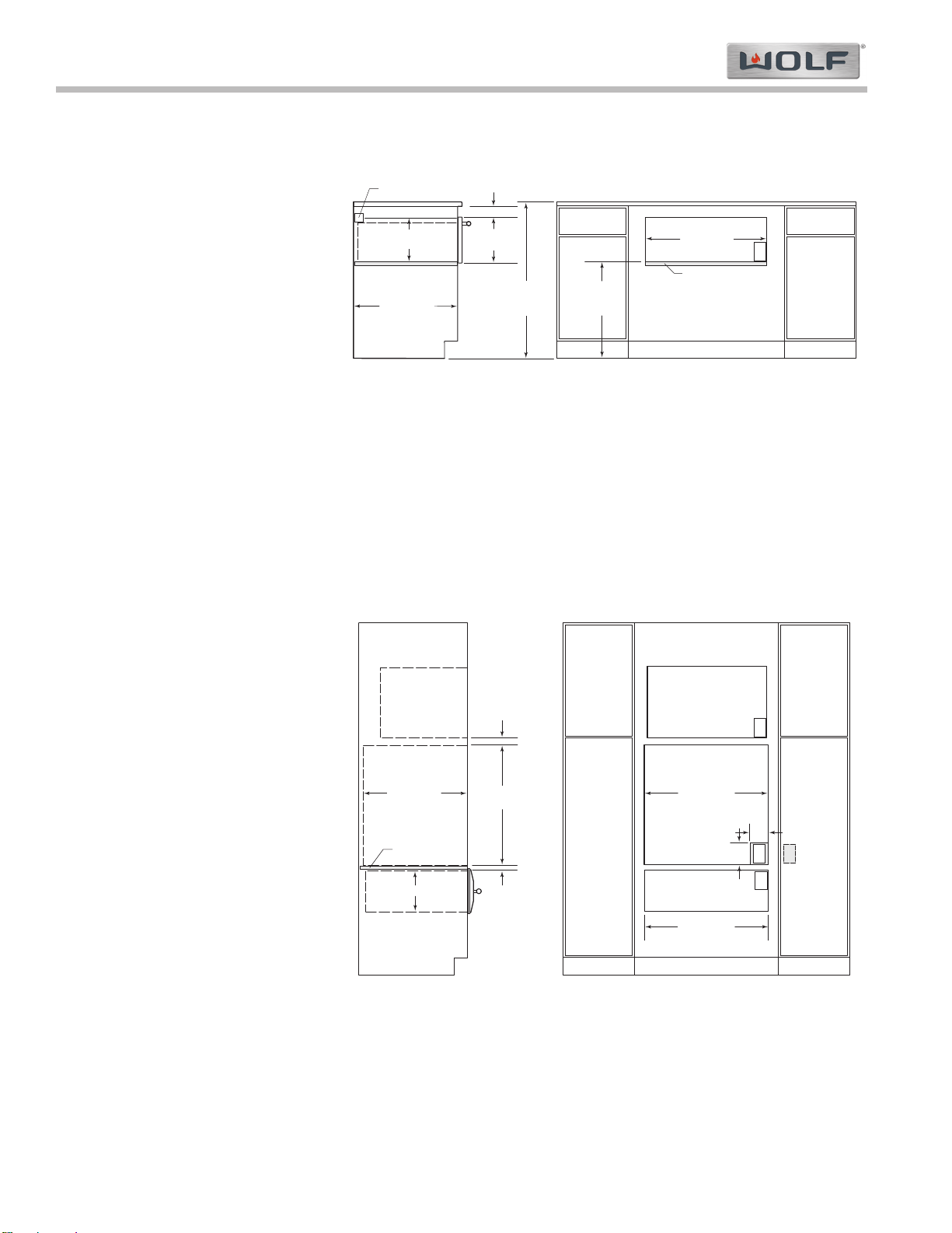
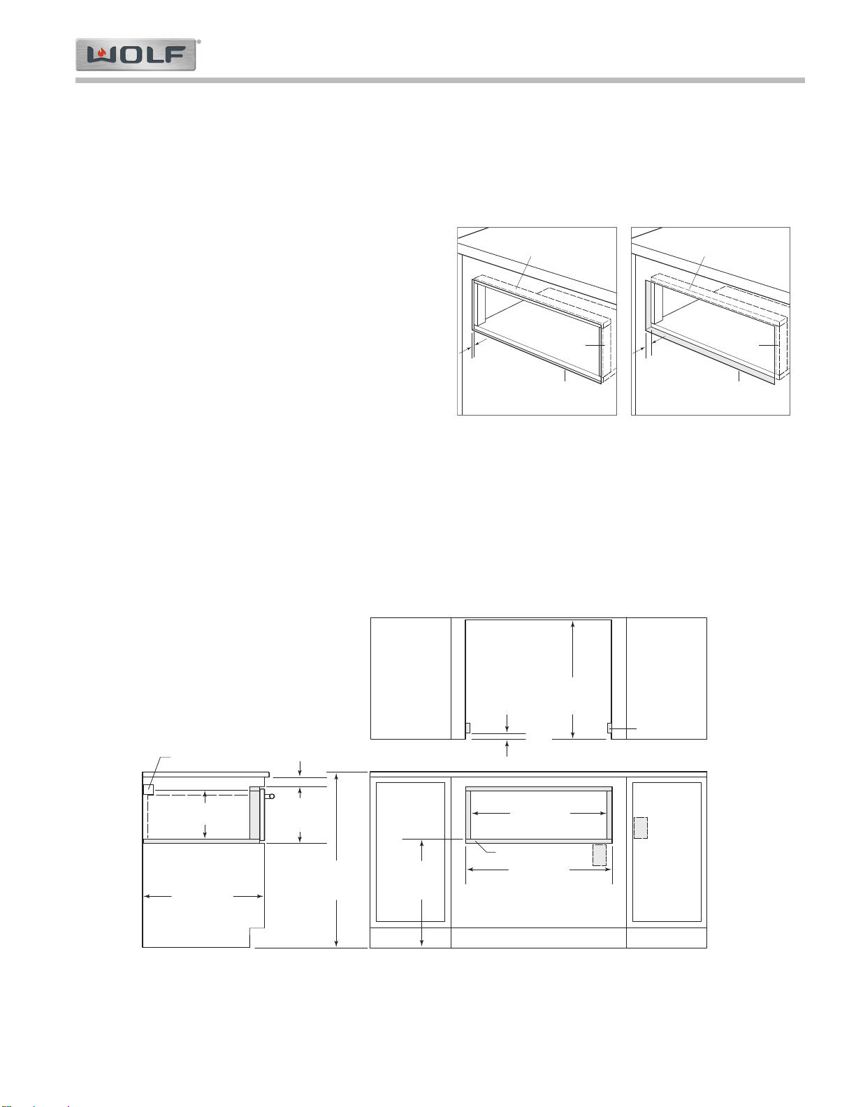
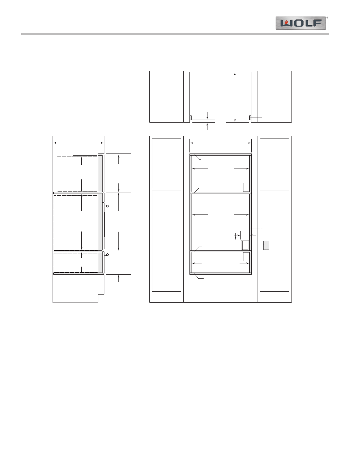
Installation Specifications......................................................2-3
Undercounter Installation......................................................2-3
WWD30 Installation with Built-In Oven.................................2-3
Section 3 - Electronic Control Information ......................3-1
Component Location ..........................................................3-2
Electronic Control System Diagram....................................3-2
Keyboard Panel Layout ......................................................3-2
Description Overview ..........................................................3-3
Element............................................................................3-3
Fan ..................................................................................3-3
Drawer Input ....................................................................3-3
User Display ....................................................................3-3
Power Key ......................................................................3-3
Temp Up/Down key ........................................................3-3
Timer Key ........................................................................3-3
System Modes ....................................................................3-4
Power Up ........................................................................3-4
On Modes ........................................................................3-4
Normal Warming Mode....................................................3-4
Preset Mode ....................................................................3-5
Temperature Maintenance ..............................................3-6
End of Warming Time......................................................3-7
Off Modes ........................................................................3-7
Timer Mode......................................................................3-7
Sabbath Mode ................................................................3-8
Showroom Mode..............................................................3-8
User Preference Setup ......................................................3-9
User Preference Offsets ..................................................3-9
Temperature Display Preference ....................................3-9
Display Contrast Change ................................................3-9
LED Back Lighting Change ..........................................3-10
Field Service Mode ..........................................................3-11
Initiating Diagnostics Mode ............................................3-11
Field Service Mode Keystrokes ....................................3-12
Error Code Troubleshooting Guide ................................3-12
Field Service Mode Functional Test Keystrokes ..........3-13
Mode/Function Unique Keystrokes................................3-13
Page #

Page 4
Warming Drawer WWD30-2
General Information
1-4
#814750 - Revision A - January, 2011
WARRANTY INFORMATION
This page contains a copy of the One (1) Year Outdoor Warranty supplied with every Wolf unit designed for outdoor
use. On the following page is the serial number information, which is needed for warranty purposes.
WARRANTY INFORMATION
This page contains a summary of the 2 & 5 Year
Warranty that is supplied with most Wolf products
designed for indoor use, the Full One Year Warranty
for Wolf outdoor products, followed by a Non
Residential Warranty summary, then notes about the
warranties.
TWO & FIVE YEAR Warranty Summary
• Two year TOTAL PRODUCT warranty, parts and
labor.
• Limited Parts Only Warranty for the 3rd through 5th
year on the following parts: heating element, elec-
tronic control system.
NOTE: This warranty only applies to products
properly installed for normal residential use in the
United States or Canada.
OUTDOOR PRODUCTS LIMITED WARRANTY
• Full One Year Product Warranty:
This warranty covers the cost of all parts and labor
to repair or replace any part of the product that
proves to be defective in materials or workmanship during the first year.
• Limited LIfetime Warranty:
Wolf Appliance will repair or replace any outdoor gas grill body or hood that rusts through due to defective materi-
al or workmanship. Labor to remove and replace defective parts is not covered.
NON RESIDENTIAL Warranty Summary
• Two year TOTAL PRODUCT warranty, parts and labor.
NOTE: This warranty only applies to products installed in test kitchens, culinary and school kitchens, and other
installations which help promote Wolf Appliance products. Restaurant installations and other similar commercial
applications carry no warranty.
Warranty Notes:
•All warranties begin at the time of the unit's initial installation.
•All Warranty and Service information collected by Wolf Appliance Inc. is arranged and stored under the unit serial
number and/or the customer's name. It is requested to have the model and serial number available whenever
contacting the factory or parts distributor.
• See Figure 1-1 serial tag location and Figure 1-2 serial tag layout.
• All warranty repairs must be performed by a Wolf authorized service center, unless otherwise specified by Wolf
Appliance.
• “ICB: warranties vary by Country and Distributor. Contact selling Distributor for warranty coverage.
Wolf Appliance Company, INC.
VOLTS :
Hz :
MODEL# : WWD30
WOLF WARMING DRAWER
FOR HOUSEHOLD USE ONLY
120
50/60
"DO NOT IMMERSE IN WATER" "NE PAS PLONGE DANS L'EAU"
Fitchburg, WI
SERIAL# :
WATTS:
OUTDOOR APPROVED
Figure 1-1. Serial tag location
Figure 1-2. Serial tag
Serial Tag is below drawer
on floor of appliance, visi-
ble with drawer fully open

Page 5
General Information
Warming Drawer WWD30-2
1-5 #814750 - Revision A - January, 2011
POWER
ON/OFF
TEMP
HIGH
MED
PRESETS
LOW
TIMER
PROOF
Warming Drawer Model Features
Figure 1-3. Keypad Layout
Rack for stacking food
Removable Stainless
Steel Drawer
Stainless Steel Drawer Front
(Classic, Carbon and Platinum
Finishes Available)
Hidden Touch Control Panel
(See Figure 1-3)
Stainless Steel Interior
Galvanized Metal Exterior
LCD Display Power On/Off
Temperature Control Presets
Timer
(Can be used as Kitchen Timer)
Outdoor Model WWD30O is specifically designed and safe for outdoor applications and can also be installed
indoors.

Page 6
Warming Drawer WWD30-2
Installation Information
2-2
#814750 - Revision A - January, 2011
INSTALLATION INFORMATION
The Wolf Warming Drawer is designed to be set into a built-in wall or cabinet installation.
This section of the manual covers some of the installation issues that a service technician may need to know when
servicing a Wolf warming drawer. If additional installation information is needed after reviewing this section of the
manual, please refer to the installation guide or contact Wolf Appliance, Inc. Customer Service Department at (800)
332-9513.
Electrical Requirements:
NOTE:All National Electrical Code regulations must be followed. In addition, be aware of local codes and ordi-
nances when installing your service.
• Dedicated 110 to 120 Volts AC, 60Hz, 15 or 20 ampere fused electrical supply
• Separate electrical circuit serving only this appliance
• A properly grounded 3-prong receptacle
Outdoor applications require that the unit be connected to a properly grounded GFCI circuit.
Line
Voltage
(Power)
Neutral
Ground
TO AVOID SHOCK HAZARD, THE INSTALLATION SITE MUST BE EQUIPPED WITH A PROPERLY GROUNDED
3-SLOT RECEPTACLE TO MATCH THE 3-PRONG (GROUNDED) POWER SUPPLY CORD PROVIDED ON THE
APPLIANCE.
TO AVOID SHOCK HAZARD, NEVER REMOVE THE GROUND PRONG FROM THE PLUG OF THE POWER
SUPPLY CORD.
Figure 2-1. Electrical Receptacle
NOTE:
This appliance must be installed in accordance with National Electrical Codes, as well as all state, munici-
pal and local codes. The correct voltage, frequency and amperage must be supplied to the appliance from a dedi-
cated, grounded circuit which is protected by a properly sized circuit breaker or time delay fuse. The proper voltage,
frequency, and amperage ratings are listed on the product rating plate.

Page 7
Installation Information
Warming Drawer WWD30-2
2-3 #814750 - Revision A - January, 2011
Cabinet Supports:
NOTE:
When the warming drawer is installed with a built-in oven, additional clearance between openings may be
required. Check that oven supports do not obstruct the interior dimensions required for the warming drawer.
NOTE:Dimensions in parentheses are in millimeters unless otherwise specified.
The warming drawer may be supported by either a solid 7/8” (22) platform or 2" (51) x 2" (51) or 2" (51) x 4" (102)
runners. The platform or runners must be level, rigidly mounted and flush with the bottom edge of the opening.
They must be able to support 200 lbs. (90.7 kg).
NOTE:
Make sure that the platform or runners are level. There is no way to level the warming drawer once it has
been installed.
Warming Drawer Installation:
Install a 2" (51) x 2" (51) or 2" (51) x 4" (102) anti-tip block
against the rear cabinet wall.
Turn power off to the electrical outlet.
Slide the left corner of the warming drawer into the open-
ing.
NOTE:A 6 foot power cord is supplied with the unit.
Depending on the outlet location, the unit can be set in
front of opening and plugged in.
If the electrical outlet is installed inside the opening, plug
the power cord into the outlet. The excess cord should be
coiled and secured directly behind warming drawer. If the
outlet is located in an adjacent cabinet, thread the power
cord through the hole in the cabinet wall. Push the drawer
back into the opening until the front flange is flush with
the cabinet front. Make sure the power cord does not get
trapped under the warming drawer.
Open the warming drawer to its full extension. Then, drill pilot holes in each corner of the warming drawer through
holes in the side frame and install the wood screws provided with the unit. (See Figure 2-2)
Figure 2-2. Drilled Pilot Holes for Securing Unit
Pilot Holes
MODEL WWD30
with Stainless Steel Drawer & Integrated Front
Overall Width 29 7/8" (759)
Overall Height 10 3/8" (264)
Overall Depth 26 1/4” (689)
Overall Depth (behind frame) 22 3/4" (578)
Minimum Cabinet Width 30" (762)
Minimum Cabinet Depth 24" (610)
Minimum Base Support 200 lbs (91 kg)
Opening Width 28 5/8" (727)
Opening Height 9 1/8" (232)
Opening Depth 23 7/8” (606)
Dimensions may vary to +
–1/8" (3).
Allow 3/8” (11) Additional depth for cord thickness
22
3
/
4
"
(578)
9"
(229)
10
3
/
8
"
(264)
29
7
/
8
"
(759)
26 1/4” (667)
OVERALL DEPTH
OVERALL WIDTH BEHIND FRAME
Figure 2-4. Overall Cabinet Dimensions
Installation Specifications:
The following pages provide the overall dimensions, finished rough
opening dimensions and electrical placement for the Wolf warming
drawer with stainless steel drawer front. For information on integrat-
ed Drawer Fronts, see the installation instructions provided with the
product.
Wolf recommends using a 33" (838) wide cabinet for the warming
drawer with stainless steel drawer front. A minimum 30" (762) wide
by 24" (610) deep cabinet is required with a minimum base support
of 200 lbs (91 kg). (See Figure 2-3 and 2-5)
Figure 2-3. Overall Unit Dimensions
Anti-Tip Block

Page 8
Warming Drawer WWD30-2
Installation Information
2-4
#814750 - Revision A - January, 2011
Undercounter Installation:
For undercounter installations, 23 1/2"
(597) from the bottom of the warming
drawer opening to the floor is recom-
mended. Electrical can be installed
anywhere except location shown. A
minimum of 5" (127) above the floor
or 1" (25) above the toe kick.
The Wolf warming drawer with stain-
less steel drawer front may be
installed below an electric or gas
cooktop, provided the warming drawer
is fully enclosed, top and bottom.
Refer to installation instructions for
the cooktop for additional specifica-
tions. Dimensions will vary according
to the specific installation.
(See Figure 2-5)
Warming Drawer Installation with Built-In Oven and/or Microwave:
The warming drawer may be installed in combination with a Wolf built-in oven and/or microwave, provided the
warming drawer is fully enclosed, top and bottom. See Figure 2.6
NOTE: Dimensions will vary according
to the specific installation.
The Wolf warming drawer is designed
and agency approved for installation
with Wolf built-in ovens and/or
microwaves. See the label attached to
the top of the warming drawer for
approved models.
The warming drawer platform must be
able to support 200 lbs. (91 kg). It must
be a minimum of 1" (25) above the toe
kick to allow for the overlap of the warm-
ing drawer trim.
NOTE:
Additional clearance between
warming drawer and oven openings may
be required. Check that oven supports
do not obstruct the interior dimensions
required for the warming drawer.
When the warming drawer is installed
below a built-in oven, a minimum of
2 3/8" (60) between warming drawer
and oven openings is required for clear-
ance of overlaps. When installed above
a built-in oven, a minimum of 7/8" (22) is required.
NOTE:
When the warming drawer is installed above a built-in oven, a 7/8" (22) platform is required to allow for
clearance of overlaps.
24"
(610) min
OPENING DEPTH
*P latform mus t s upport 250 lbs
(113 kg)
.
NO TE : L ocation of electrical s upply within oven opening ma y require additiona l cabinet depth.
FRONT VIEWSIDE VIEW
28
5
/
8
"
(727)
WARMING DRAWER
OPENING WIDTH
28
1
/
2
"
(724)
OVEN OPENING WIDTH
E
E
MICROWAVE
OPENING
27
3
/
16
"
(691)
1
1
/
2
"
(38) min
E SERIES
1"
(25) min
L SERIES
9
1
/
8
"
(232) 3
/
4
"
(19)
min
PLATFORM*
E
E
5"
(127)
4"
(102 )
ANTI-TIP BLOCK
DIMENSION
WILL VARY*
*Dimens ion mus t accommodate height of anti-tip block and drawer face overlap.
NOT E : Location of electrical supply within opening may require additional cabinet depth. Dashed line repres ents profile of unit.
FRONT VIEWSIDE VIEW
E
24"
(610) min
CABINET DEPTH
28
5
/
8
"
(727)
OPENING WIDTH
PLATFORM
9
1
/
8
"
(232)
OPENING HEIGHT
10
3
/
8
"
(264)
23
1
/
2
"
(597)
TYPICAL
36"
(914)
FLOOR TO
COUNTERTOP
Figure 2-5. Undercounter Installation
Figure 2-6. Installation with Built-In Wall Oven and/or Microwave

Page 9
Installation Information
Warming Drawer WWD30-2
2-5 #814750 - Revision A - January, 2011
Recessed or Flush Inset Installation
In addition to the standard installation the warming drawer with E series drawer front can be installed in a recessed
or flush inset application. A recessed installation requires the cabinetry be recessed by 3/16" (5) so the collar is flush
with the cabinet face frame but the drawer front will sit proud. A flush inset installation requires the drawer collar and
front panel be recessed to be flush with surrounding cabinetry. Refer to illustrations on the following pages for mini-
mum cabinet dimensions for your specific installation.
Install Recessed Cleats and Platform
For a recessed or flush inset application, you will need to
install a recessed platform and cleats into the opening.
Proper recess of the platform and cleats is critical to the
function and esthetics of the warming drawer installation.
The depth of the platform may increase with the cabinet
depth. Be sure to rigidly mount the platform so that it
can support a minimum of 200 lbs (91 kg). (See Figure 2-7)
Mounting holes will need to be drilled in the back of the
drawer front panel. Holes should be drilled on site to
ensure proper fit and gaps are achieved. A drilling
template is provide with the integrated drawer front.
NOTE:
Be sure to finish the inside lip of the opening and the front face of the platform and cleats. These areas
may be visible when the drawer is open.
NOTE:
Be aware of the location of the mounting holes on the warming drawer frame to make sure screws used to
attach the cleats do not interfere with screw holes for mounting the warming drawer.
Flush Inset Installation Under Counter
PLATFORM
TOP CLEAT
SIDE CLEAT
CABINETRY
OPENING
CLEATS AND PLATFORM
RECESSED
3
/
16
"
(5)
R ec es s ed applic ation. F lus h ins et applic ation.
PLATFORM
TOP CLEAT
SIDE CLEAT
CABINETRY
OPENING
CLEATS AND PLATFORM
RECESSED
3
/
16
"
(5)
PLUS THICKNESS
OF DECORATIVE PANEL
Figure 2-7. Install Platform and Cleats
DIMENSION
WILL VARY*
23
1
/
2
"
(597)
TYPICAL
*Dimension must accommodate height of anti-tip block and drawer face overlap.
NOTE : Dimensions provided allow for
1
/
4
" (6) reveal for proper air flow. Location of electrical supply within opening may require additional
cabinet depth. Dashed line repres ents profile of unit.
FRONT VIEWSIDE VIEW
24"
(610) min
CABINET DEPTH
30
3
/
8
"
(772)
FLUSH INSET WIDTH
28
5
/
8
"
(727)
OPENING WIDTH
7
/
8
"
(22)
PLATFORM
7
/
8
"
(22)
TOP AND SIDE CLEATS
36"
(914)
FLOOR TO
COUNTERTOP
10
7
/
8
"
(276)
FLUSH INSET
HEIGHT
9
1
/
8
"
(232)
OPENING HEIGHT
E
E
SIDE CLEATS
24
(610) min
FLUSH INSET
DEPTH
1"
(25)
TOP VIEW
ANTI-TIP BLOCK

Page 10
Warming Drawer WWD30-2
Installation Information
2-6
#814750 - Revision A - January, 2011
Flush Inset Tower Installation
25"
(635) min
CABINET DEPTH
30
3
/
8
"
(772) min
FLUSH INSET WIDTH
SIDE CLEATS
24
3
/
4
"
(629) min
FLUSH
INSET
DEPTH
1"
(25)
*
Platform mustsupport 250 lbs
(113 kg).
NOTE : Location of electrical s upply within oven opening may require additional cabinet depth. Dashed line repres ents profile of unit.
FRONT VIEWSIDE VIEW
TOP VIEW
10
5
/
8
"
(270)
FLUSH INSET
HEIGHT
9
1
/
8
"
(232)
OPENING HEIGHT
E
1"
(25)
PLATFORM
28
5
/
8
"
(727)
WARMING DRAWER
OPENING WIDTH
17"
(432)
OPENING
HEIGHT
18
1
/
2
"
(470)
FLUSH INSET
HEIGHT
27
1
/
2
"
(699)
STANDARD MICROWAVE
OPENING WIDTH
E
28
1
/
2
"
(724)
E SERIES OVEN
OPENING WIDTH
11
/
16
"
(17)
TOP CLEAT
9
/
16
"
(14)
PLATFORM*
1"
(25)
SIDE CLEATS
E
E
5"
(127)
4"
(102)
27
3
/
16
"
(691)
OPENING
HEIGHT
28
1
/
8
"
(714) min
FLUSH INSET
HEIGHT
1
11
/
16
"
(43)
PLATFORM
INSTALLATION WITH STANDARD MICROWAVE AND E SERIES OVEN

Page 11
Installation Information
Warming Drawer WWD30-2
2-7 #814750 - Revision A - January, 2011
Flush Inset Tower Installation
25"
(635) min
CABINET DEPTH
30
3
/
8
"
(772) min
FLUSH INSET WIDTH
SIDE CLEATS
24
3
/
4
"
(629) min
FLUSH
INSET
DEPTH
1"
(25)
*
Platform must support 250 lbs
(113 kg).
NOTE : Location of electrical supply within oven opening may require additional cabinet depth. Dashed line repres ents profile of unit.
FRONT VIEWSIDE VIEW
TOP VIEW
10
5
/
8
"
(270)
FLUSH INSET
HEIGHT
9
1
/
8
"
(232)
OPENING HEIGHT
E
1"
(25)
PLATFORM
28
5
/
8
"
(727)
WARMING DRAWER
OPENING WIDTH
18
7
/
8
"
(479)
OPENING
HEIGHT
20
1
/
8
"
(511)
FLUSH INSET
HEIGHT
27
1
/
2
"
(699)
CONVECTION MICROWAVE
OPENING WIDTH
E
28
1
/
2
"
(724)
E SERIES OVEN
OPENING WIDTH
1
/
2
"
(13)
TOP CLEAT
9
/
16
"
(14)
PLATFORM*
1"
(25)
SIDE CLEATS
E
E
5"
(127)
4"
(102)
27
3
/
16
"
(691)
OPENING
HEIGHT
28
1
/
8
"
(714) min
FLUSH INSET
HEIGHT
1
5
/
8
"
(41)
PLATFORM
INSTALLATION WITH CONVECTION MICROWAVE AND E SERIES OVEN

Page 12
Warming Drawer WWD30-2
Installation Information
2-8
#814750 - Revision A - January, 2011
Flush Inset Tower Installation
27
3
/
16
"
(691)
OPENING
HEIGHT
28
1
/
8
"
(714) min
FLUSH INSET
HEIGHT
28
1
/
2
"
(724)
E SERIES OVEN
OPENING WIDTH
25"
(635) min
CABINET DEPTH
30
3
/
8
"
(772) min
FLUSH INSET WIDTH
28
1
/
2
"
(724)
DRAWER MICROWAVE
OPENING WIDTH
E
7
/
8
"
(22)
TOP CLEAT
9
/
16
"
(14)
PLATFORM*
5
/
8
"
(16)
PLATFORM
SIDE CLEATS
24
3
/
4
"
(629) min
FLUSH
INSET
DEPTH
1
1
/
4
"
(32)
FOR MICROWAVE
1"
(25)
FOR
OVEN
AND WARMING
DRAWER
*
Platform mustsupport 250 lbs
(113 kg.
NOTE : Location of electrical supply within oven opening may require additional cabinet depth. Dashed line repres ents profile of unit.
FRONT VIEWSIDE VIEW
TOP VIEW
14
3
/
4
"
(375)
OPENING
HEIGHT
15
3
/
8
"
(391)
FLUSH INSET
HEIGHT
1"
(25)
SIDE CLEATS
10
5
/
8
"
(270)
FLUSH INSET
HEIGHT
9
1
/
8
"
(232)
OPENING HEIGHT
E
1"
(25)
PLATFORM
28
5
/
8
"
(727)
WARMING DRAWER
OPENING WIDTH
E
E
5"
(127)
4"
(102)
INSTALLATION WITH DRAWER MICROWAVE AND E SERIES OVEN

Page 13
Warming Drawer WWD30-2
Electronic Control Info.
3-2
#814750 - Revision A - January, 2011
GENERAL INFORMATION:
Electronic control will provide temperature control in the warming drawer as determined and set by user. Up and
down arrow keys are provided to increase and decrease, respectively, the temperature of the drawer and operation
time. Temperature control range of the warming drawer main board control will be 80ºF to 200ºF (26.7ºC to 93.3ºC).
Amplitude of this temperature control will be ± 5ºF. When the control sees a temperature at the thermistor 5ºF above
set-point, control will open the element relay. Once the control sees a thermistor temperature of 5ºF below set-point,
the relay will close allowing element to cycle on.
Power/Relay Board
Circulation Fan
Element
Display Board/
Keypad
Flex Cable
(Inner ceiling)
(Network Cable)
Electronic Control Board
(Behind Front Panel)
Door Switch
(Bottom of Drawer Front)
Display
Beeper
CONTROL (all low
temp components)
Keypad
Communications
Thermistor POWER BOARD
AC Fan
Element
(850W)
Flex Cable
Door Input
DLB
(CB/CE Model only)
Figure 3-1. Component Location Top View.
Figure 3-2. Electronic Control System Diagram.
TIMER
PROOF
LOW
PRESETS
HIGH
MED
TEMP
POWER
ON/OFF
PROOF
F
TEMPTEMPTEMP
ON TIMER
LCD Display Power On/Off Temperature
Controls
Preset Controls Timer Controls
Figure 3-3. Keyboard Layout.

Page 14
Electronic Control Info.
Warming Drawer WWD30-2
3-3 #814750 - Revision A - January, 2011
DESCRIPTION OVERVIEW:
Element:
The element will be powered by the element relay (normally-open contacts). This allows the element to be disabled
under most conditions. Only during a call for heat from the main controller, will the element relay be energized.
Fan:
The fan will be powered by the fan relay (normally-open contacts). This allows the fan to be disabled under most
conditions. Only during a warming mode from the main controller, will the fan be in use.
Drawer Input:
The drawer switch will be a normally open switch, (when drawer is open), and closed when drawer is closed.
When drawer is opened and is in a normal heating mode, unit will de-energize relays to fan and element. If back
lighting of the LCD is enabled, then opening of the drawer will turn on back lighting, and by closing the drawer, back
lighting will go off.
NOTE:Sabbath mode has unique requirements. Please see Sabbath mode this section.
User Display:
The user display shows warming drawer preset temperature, any timed feature which is in process, and whether the
unit is in Proof mode. Other indicators include the ‘ON’ indicator which notes when unit is heating, (always on when
in the Sabbath mode), and displays which temperature units, (°F or °C), the temperature is being displayed in.
This area also informs user if there is an issue with the control and will display an error code in the temperature
and/or timer display. The user display numbers will be displayed as shown in the following pages.
The characters in the user display will only be illuminated when a normal warming mode, service diagnostic mode, or
kitchen timer is being used. At all other times, display will be remain off.
The “PROOF” is on anytime “PROOF” mode is being used.
The “ON” indicator is on anytime control is calling for heat. The exception is during Sabbath mode where the ”ON”
indicator stays on constantly.
NOTE:“TIMER” is on anytime there is a timed warming event or if kitchen timer is being used.
NOTE: “TIMER” is not an option in Sabbath mode.
POWER Key:
The “POWER” key is used to turn unit on and off. While unit is in “OFF” mode, the Power key and “TIMER” up and
down arrow keys remain active. If unit is powered up and Power key is pressed, the display will turn off along with
any associated backlighting. If unit is off and the Power key is pressed, the control backlighting (if applicable), will
turn on and the rest of the keys will be active.
NOTE: If no other key is pressed within 20 seconds, unit will turn off.
TEMP Up/Down Key:
The “TEMP” up or down arrow keys can be used to adjust temperature. By pressing and holding the up or down
arrow, unit will begin changing at the rate of 1º per ½ second until the first 5º increment is obtained. If the user con-
tinues pressing, control will increment in 5º increments per ½ second. The “TEMP” up or down arrow keys remain
active as long as control is On.
NOTE: Exception to this is in the Sabbath Mode.
NOTE: Temperature range is 80ºF to 200ºF, except in “PROOF” mode where maximum temperature is 120ºF.
TIMER Key:
The “TIMER” up or down arrow key is used to change time left in normal warming mode. Timer keys can also be
used as a Kitchen Timer. The rate of this ascension shall be ½ second per increment and in the following order: one
minute from 1-5 minutes; every five minutes from 5-30 minutes; 30 minute increments up to 5 hours; then hourly up
to 24 hours. At any time during a Normal Heating Mode, operator can adjust time left for warming by pressing
“TIMER” up or down arrow keys.
NOTE:The exception to this is during the Sabbath Mode (only the “Power On/Off” key is active in this mode).

Page 15
Warming Drawer WWD30-2
Electronic Control Info.
3-4
#814750 - Revision A - January, 2011
SYSTEM MODES:
The control can be placed into several different operational modes which changes preset conditions inside the warm-
ing drawer. Details as to what each mode does to the operation of the drawer can be found below.
POWER UP:
Power up is defined as the initial application of power to the appliance through the power cord; not to be confused
with switching the unit on/off with the “Power On/Off” key. During power up, all segments of the LCD will illuminate
for 5 seconds before the unit goes into off mode.
After entering unit off mode, display will show “PF” in the time display until user presses a key. If unit was previously
in a warming mode prior to power loss, control will also emit a power failure chime every 30 seconds while displaying
“PF” until the “Power On/Off” is pressed.
NOTE: Pressing any key will clear “PF” error and unit will operate normally.
ON MODES:
ON Modes control behavior of electrical components of the appliance when it is “ON”. Switching the unit on is
accomplished buy pressing the “Power On/Off” key. When ON, any back lighting will immediately activate “- - -” will
be displayed in the temperature display with the respective temperature scale (F or C) blinking. (See Figure 3-4)
NOTE: If no other key is pressed within 20 seconds, unit will switch off.
NORMAL WARMING MODE:
Normal warming mode is the basic operating mode when power is turned on and any warming function is selected.
This will include heating by the element and circulation of air by use of the fan.
Mode Entry:
The unit can be placed into a normal warming mode by simply pressing the “Power On/Off” key followed by either
“TEMP” up or down arrow keys, or any preset is pressed. (See Figure 3-4)
NOTE: If no other key is pressed within 20 seconds, unit will switch off.
Operations:
Once unit is turned on and “TEMP” up or down arrow is pressed, unit will initiate at 120°F and can be adjusted in
increments of 1°F. If you press and hold either arrow, the display will increase by 1° each 1/2 second until the first 5°
increment is obtained then will increase by 5° per 1/2 seconds. (See Figure 3-5)
NOTE: Temperature is adjustable from 80°F to 200°F (26.7°C to 93.3°)
Mode Exit:
Pressing “Power On/Off” key will terminate Normal Warming Mode and shut unit off.
NOTE:The mode will also exit by reaching ‘0:00,’ on the timer. At this point, ‘0:00’ will begin flashing and the ele-
ments and fan will shut off. The control will also yield three chimes every 30 seconds to denote unit has shut off.
After 5 minutes the timer will self power down if the “Power On/Off” key is not pressed.
TIMER
PROOF
LOW
PRESETS
HIGH
MED
TEMP
POWER
ON/OFF
PROOF
F
TEMPTEMPTEMP
ON TIMER
Figure 3-5. Temperature Adjustment in Normal Warming Mode.
TIMER
PROOF
LOW
PRESETS
HIGH
MED
TEMP
POWER
ON/OFF
PROOF
F
TEMPTEMPTEMP
ON TIMER
Figure 3-4. Power On Mode.

Page 16
Electronic Control Info.
Warming Drawer WWD30-2
3-5 #814750 - Revision A - January, 2011
NORMAL WARMING MODE:
Operations: (Continued)
If temperature of unit is greater than 10ºF above set-point, control will chime and “hot” will flash in the temperature
display. Control will continue to check if temperature has dropped, every 20 seconds. Once temperature, as moni-
tored by the thermistor, is within 10°F of set temperature, set temperature will be displayed and resume cycling nor-
mally. “HOT” indicator will no longer be illuminated. (See Figure 3-6)
NOTES:
•If drawer is closed at the time of power down, control will initiate a failure tone.
•If no time is set, timer will automatically default to 4:00 hours. This ensure a definitive stop time. This does not
occur in Sabbath Mode.
•If any presets are depressed, unit will begin to function. See Preset for further information.
•During normal warming mode, all keys remain active to allow for changes to mode.
PRESET MODES: (High, Medium and Low Presets)
Mode Entry:
Press “Power On/Off” key followed by either the HIGH, MED or LOW preset key. (See Figure 3-7)
NOTES:
•“TIMER” will illuminate and flash when first entering mode. Once mode is active the “TIMER” will no longer be
illuminated.
•If no time is set, timer will automatically default to 4:00 hours. This ensures a definitive stop time.
Operations:
When “HIGH” Preset key is depressed, control will display “200F” in temperature display. For “MED” temperature
display will read “160F” and for “LOW” temperature display will read “120F”. In timer area of display, “4:00” along
with “TIMER”’ will be flashing. Temperature can be adjusted by pressing the “TEMP” up or down arrow keys. By
touching the “TIMER” up or down arrow keys, additional time can be added or subtracted. Anytime a change is
being made, the control begins flashing the changing value. Mode activation time for the control will be 2 seconds
and the “ON” indicator will illuminate and “TIMER” will no longer be illuminated.
Mode Exit:
Pressing “Power On/Off” key will cancel preset and any related timer feature of this mode. If timer expires during
preset mode, and after signaling end of time chime for 5 minutes, the unit will time out and power off.
TIMER
PROOF
LOW
PRESETS
HIGH
MED
TEMP
POWER
ON/OFF
PROOF
F
TEMPTEMPTEMP
ON TIMER
Figure 3-6. “HoT” Indication if Temperature of unit is 10° above set-point.
TIMER
PROOF
LOW
PRESETS
HIGH
MED
TEMP
POWER
ON/OFF
PROOF
F
TEMPTEMPTEMP
ON TIMER
Figure 3-7. Example of “LOW” preset.

Page 17
Warming Drawer WWD30-2
Electronic Control Info.
3-6
#814750 - Revision A - January, 2011
PRESET MODES: (Proof Mode)
Proof mode allows the customer to use the warming drawer for bread dough proofing. (See Figure 3-8)
Mode Entry:
Press the “Power On/Off” key followed by the “PROOF” key.
Operations:
Upon pressing the “PROOF” key. Control will display “85F” in the temperature display. In the timer area of display,
‘“4:00” along with “TIMER” will be flashing. Temperature can be adjusted by pressing the “TEMP” up or down arrow
keys. By touching the TIMER up or down keys, additional time can be added or subtracted from this mode. Anytime
a change is being made, the control begins flashing the changing value.
The mode activation time for the control will be 2 seconds at which time the ‘ON’ indicator will illuminate and
changes will be applied and additional indicators will stop flashing.
NOTE: Circulation fan runs while heating element is on during Proof Mode.
NOTE: If the unit is greater than 10ºF above the set-point, control will chime and “hot” will flash in the temperature
display until the unit temperature is within 10° of set temperature. The control will continue to check if temperature
has dropped every 20 seconds.
Mode Exit:
Pressing “Power On/Off” key will cancel this mode and any related timer feature. If timer expires during “PROOF”,
and after signaling end of time chime for 5 minutes, unit will time out and power off.
TEMPERATURE MAINTENANCE:
During temperature maintenance, element and fan maintains drawer temperature to set-point temperature. Fan is on
while element is on during warming mode, (as long as drawer switch returns a drawer closed value). If element has
cycled off, fan will continue to circulate air inside drawer for a pre-determined time before turning off. Fan will then
re-energize when element is turned back on during a call for heat.
PREHEAT:
Preheat can be described as the control operation occurring when trying to raise the temperature from more of an
ambient temperature to the operating temperature desired by the user.
Mode Entry:
The unit can be placed into a preheat mode by simply pressing the “Power On/Off” key and any other keys, when
the drawer is cool (room temperature or less than set-point).
Operations:
If the “TEMP” up or down arrow key is pressed, unit will initiate at “120F” and can be adjusted in increments of 1°.
NOTE: If you press and hold either arrow, the display will increase by 1° each 1/2 second until the first 5° increment
is obtained then will increase by 5° per 1/2 second.
During preheat, control temperature read out will toggle between the set-point and actual drawer temperature. At
temperatures lower than 85F, “LO” will be displayed. Temperatures equal to or greater than 85F, the actual tempera-
ture measured by the thermistor and set-point temperature, will be toggled back and forth at a rate of 5 seconds.
Once temperature has reached desired set-point temperature, control will emit a chime.
Mode Exit:
A press of the “Power On/Off” key will terminate Preheat mode and shut unit off.
TIMER
PROOF
LOW
PRESETS
HIGH
MED
TEMP
POWER
ON/OFF
PROOF
F
TEMPTEMPTEMP
ON TIMER
Figure 3-8. Example of “PROOF” preset.

Page 18
Electronic Control Info.
Warming Drawer WWD30-2
3-7 #814750 - Revision A - January, 2011
END OF WARMING TIME:
Upon reaching “0:00”, “0:00” will begin flashing. Element and fan will shut off at this time. Control will also emit
three chimes every 30 seconds to denote unit has shut off. After 5 minutes the timer will power down and turn unit
off.
NOTE: Operator can cancel chime earlier by pressing the “Power On/Off” key.
OFF MODES:
This mode is obtained by pressing the “Power On/Off” key once unit is in any “On” mode. All active modes on unit
will be cancelled, including Sabbath Mode.
TIMER MODE:
This allows the unit to be used as a kitchen timer, if so desired. (See Figure 3-9)
Mode Entry:
To set timer, first depress “TIMER” up or down arrow keys. “TIMER” will be flashing in display. Press “TIMER” up
arrow key and unit begins counting up from “00:00”.
NOTE: Pressing and holding “TIMER” up or down arrow key, display will increase, or decrease, by 1 second each
1/2 second until the first 5 second increment is obtained then will increase by 5 seconds per 1/2 second. If “TIMER”
up or down arrow key is depressed for longer than 30 seconds display will increase by 30 minute increments each
1/2 second until 5:00 Hours is reached then increase in one hour increments up to 24:00 hours.
NOTE: Timer will count up in time with 1 minute as the minimum setting and going up to 24:00 (hours:minutes).
Operations:
In Timer mode, the temperature display will show nothing and “ON” indicator will not illuminate.
Once set, this timer will count down in hours and minutes. Upon reaching 1 minute, the control will produce an audi-
ble tone.
Mode Exit:
Upon reaching “0:00”, “0:00” will begin flashing. The control will also chime three times every 30 seconds to denote
the unit has shut off.
NOTE:After 5 minutes the timer will power down.
NOTE: Timer mode can be cancelled at any time by pressing the “Power On/Off” key.
NOTE:Operator may cancel chime by pressing “Power On/Off” key. This will also remove the flashing “0:00” from
display.
TIMER
PROOF
LOW
PRESETS
HIGH
MED
TEMP
POWER
ON/OFF
PROOF
F
TEMPTEMPTEMP
ON TIMER
Figure 3-9. Example of “TIMER” mode set at 4 minute.

Page 19
Warming Drawer WWD30-2
Electronic Control Info.
3-8
#814750 - Revision A - January, 2011
SABBATH MODE:
To accommodate observance of the Sabbath, a special mode exists where the control will only react to the “Power
On/Off” key. In Sabbath Mode, the display will not change. “ON” remains on constantly. LCD back lighting will also
remain on at all times during this mode at a rate of 50% normal power.
Mode Entry:
Starting from “Off” mode, press the “Power On/Off” key for 5 seconds. (See Figure 3-10)
Operations:
The control will flash “SAb” in timer display area and selections can be made for 5 seconds, while the “SAb” is flash-
ing, at which time control will emit a tone twice and unit will remain in Sabbath mode.
NOTES:
•If back lighting was turned off prior to entering Sabbath mode then back light will remain off.
•Selections for Sabbath mode include “TEMP” up or down arrow keys and any “PRESET” keys.
•“TIMER” up or down arrow keys will yield an invalid key press in Sabbath mode.
•If unit power is interrupted, unit will return to Sabbath Mode upon next power up.
Once in Sabbath mode, unit will read “SAb” in the timer display area. The display will show no changes. The ele-
ment cycles normally. Fan runs while element is on and for a short time after element turns off. If drawer is opened,
fan and element will not shut off.
NOTES:
•If drawer is open for longer than 1 minute and the unit calls for heat, element will randomly turn on and off.
•If in Sabbath mode but a second key press does not occur withing 10 seconds, the unit will enter “OFF” mode.
Mode Exit:
A press of the “Power On/Off” key will terminate Sabbath mode and shut off unit at any time.
TIMER
PROOF
LOW
PRESETS
HIGH
MED
TEMP
POWER
ON/OFF
PROOF
F
TEMPTEMPTEMP
ON TIMER
Figure 3-10. Press and hold Power On/Off for 5 second to enter Sabbath Mode.
SHOWROOM MODE:
Showroom mode allows unit to be run in a demonstration mode. Heating element and fan operation are disabled.
Mode Entry:
Starting from Unit Off mode, press “Power On/Off” key along with “HIGH” and “LOW” PRESET keys for 5 seconds.
A single soft tone will signify unit is in showroom mode and “Sr” will show in timer display. (See Figure 3-11)
NOTES:
•If power is turned off to unit, showroom mode will remain active.
•If unit power is interrupted (unplugged), unit will exit showroom mode upon next power up.
Operations:
Unit will function just as it normally would, but the fan and element will not energize while in this mode. The unit can
be turned on and/or off, temperature adjusted, and timer used, but the unit will not provide heat/air circulation.
Mode Exit:
Another press of the same key combination from the Showroom mode will toggle showroom mode off.
TIMER
PROOF
LOW
PRESETS
HIGH
MED
TEMP
POWER
ON/OFF
PROOF
F
TEMPTEMPTEMP
ON TIMER
Figure 3-11. Press and hold Power On/Off, HIGH and LOW PRESET Keys simultaneously for 5 seconds.

Page 20
Electronic Control Info.
Warming Drawer WWD30-2
3-9 #814750 - Revision A - January, 2011
USER PREFERENCE SETUP
NOTE: Following changes must be made when unit is in “ON” mode.
Preset Change:
Changes can be made to presets by completing the following sequence. Press “Power On/Off” key, then press pre-
set key you wish to change and hold for 5 seconds. After 5 seconds, timer display, temperature display and “TIMER”
will illuminate and flash. Using “TEMP” up or down arrow keys, and/or the “TIMER” up or down arrow keys, change
the values to your own personalized presets. After all settings are complete, press and hold the preset key being
changed for 5 seconds again. Three quick tones will signify preset has been changed and unit will shut off.
NOTES:
•“PROOF” mode can only be adjusted from 80°F to 120°F.
•Unit will turn off after 30 seconds if no key presses are made.
•Changes to preset mode entered will be saved only if key being changed is pressed and held for 5 seconds after
making changes.
USER PREFERENCE OFFSETS (UPO)
NOTES:
•Following changes must be made when unit is in “OFF” mode.
•See Figure 3-20 for a quick reference to keystrokes to enter modes and features.
Temperature Display Preference:
Control can be switched between Fahrenheit or Celsius by pressing and holding both “TEMP” up and down arrow
key for 5 seconds. Use the “TEMP” Up or Down arrow key to change from °F to °C or °C to °F. (See Figure 3-12)
NOTE: Press “Power On/Off” key to exit and save changes.
Display Contrast Change:
Display contrast can be adjusted by pressing and holding both the TIMER up and down arrow keys for 5 seconds.
Use the “TIMER” Up and/or down arrow keys to change contrast from the preset. (See Figure 3-13)
NOTE:Contrast setting is from 0 to 15 with 15 being the darkest contrast setting. Unit default is 7.
Press the “Power On/Off” key to exit and save changes.
NOTE: Unit will turn off after 30 seconds if no key presses are made.
TIMER
PROOF
LOW
PRESETS
HIGH
MED
TEMP
POWER
ON/OFF
PROOF
TEMPTEMPTEMP
ON TIMER
Figure 3-12. Press TEMP up and down arrow key to enter. Press TEMP arrow up or down to change scale.
TIMER
PROOF
LOW
PRESETS
HIGH
MED
TEMP
POWER
ON/OFF
PROOF
TEMPTEMPTEMP
ON TIMER
Figure 3-13. Press TIMER up and down arrow key to enter. Press TIMER arrow up or down to change scale.
Table of contents
Other Subzero Warming Drawer manuals
Popular Warming Drawer manuals by other brands

Asko
Asko ODW8127A/HZWE140 Instructions for use

ROSIERES
ROSIERES RDCT 140/1MIN instruction manual

V-ZUG
V-ZUG WS 60 144 operating instructions

KitchenAid
KitchenAid KOWT107ESS installation instructions

Bosch
Bosch BI.7101 Series User manual and installation instructions

Fisher
Fisher PROFESSIONAL WB76SPEX1 user guide

Siemens
Siemens HW 140 B Series instruction manual

Viking
Viking Built-In Electric Warming Drawers Quick reference guide

Electrolux
Electrolux E30WD75EPS Specifications

Baumatic
Baumatic BSWD14-ANZ Instructions for use

Bosch
Bosch BID830NC0 instruction manual

GE
GE Monogram ZKD910 B Series Technical service guide