Suin TFG6800 Series User manual

User’s Guide
TFG6800 Series
Function/Arbitrary Waveform Generators
Suin Instruments Co., Ltd 03/2021

TFG6800 Series Function/Arbitrar Waveform Generator Users’ Guide
Suin Instruments Co., Ltd 1
Introduction
With Direct Digital S nthesis technique (DDS), Field Programmable Gate Arra (FPGA) and high
sampling rate 250MSa/s, TFG6800 series are of the excellent technical performances and
powerful function characteristics which are necessar for the fast measurement. 7 inches color
LCD displa can show the illustration of output waveform and parameters. Capacitive touch
screen and eas - to - use ke pads and knobs make the operation much easier.
1 Main Features
Output Channel: Dual independent output channels with the same characteristics.
Frequency Characteristic: 20ppm Accurac .
Amplitude Offset: 1% amplitude and offset Accurac , 1mVpp Resolution.
Built-in Waveform: 165 kinds of waveform, Sine, Square, Exponential, Log, etc.
Square, Ramp: Accurate Square’s dut c cle and Ramp’s s mmetr could be set.
Pulse: Accurate pulse width and edge time could be set.
Double Pulse: Pulse width and time interval of the two Pulses could be set separatel .
Phase Characteristic: The phase and polarit that output signal relative to s nchronizing signal
could be set.
Modulation Characteristic: Total 13 t pes of modulation such as FM, AM, PM, PWM, SUM,
FSK, ASK, etc. could be supported.
Burst Output: period-settable signal and gated-controlled signal could be output.
Frequency Sweep: Support linear frequenc sweep and Logarithmic frequenc sweep signal.
Frequency sequence: High speed hop-frequenc frequenc sequence can be output..
Synthesis of harmonic: The instrument can s nthesize multiple harmonics, and ever harmonic’s
amplitude and phase can be independentl set.
Arbitrary waveform: Point b point output mode to prevent waveform’s an detail from losing.
Waveform Editing: You can use ke board editing function or computer’s edit software to edit
arbitrar wave
Waveform sequence: The instrument can output arbitrar wave sequence with different
waveform length and c cle times.
Channel Coupling: Each channel’s frequenc , amplitude and offset setting parameter can be

TFG6800 Series Function/Arbitrar Waveform Generator Users’ Guide
Suin Instruments Co., Ltd 2
intercoupling.
Storage characteristic: The instrument can store and recall several group working condition
parameters and several users’ arbitrar waveform.
Sync Output: The instrument can output corresponding signals s nchronizing on different
functions.
External Modulation: External modulation can be used when FM, AM, PM, PWM, SUM are
modulating.
External Trigger: External Trigger can be used in ke controlling, sweep, burst, double pulse,
frequenc and waveform sequence.
External Clock: It can automaticall test and use external base clock. Internal reference clock can
be output.
Counter: 8 bits/s resolution, it can test external signals’ frequenc , c cle, pulse width, dut c cle.
Touch Screen: Capacitive touch screen to make the operation more easil .
Calculation function: Values of frequenc , period, amplitude peak to peak, RMS or dBm could
be selected.
Communication interface: USB device, USB host and LAN interfaces are supported.
TCXO (option): ±1ppm accurac , ±1ppm/ ear aging rate.
Power Amplifier (option): 2 times power amplifier, Max output power 8W (8Ω).
IOT interface (option): Base on Lora wireless LAN standard.
2 Models
This User Guide is applied to TFG68xx series function/arbitrar waveform generator.
3 Packing list
TFG68xx Function/arbitrar waveform generator 1set
Three core power cord 1 pcs
BNC two ports testing cable 1 pcs
CD 1 pcs
Antenna (option) 1 pcs
Note:
This document ma include technical inaccurac , and it is onl a usage guide for the instrument. Suin
Instruments Co., Ltd. will not make an promise to this document, including but not limit to the promise for some
special sales and usage. It will not be notified if there were an modification in this documentation.

TFG6800 Series Function/Arbitrar Waveform Generator Users’ Guide
Suin Instruments Co., Ltd 3
Content
Chapter 1 Quick Start ........................................................................................................................ 5
1.1 Preparation for usage .............................................................................................................. 5
1.2 Front and Rear Panel ............................................................................................................... 6
1.3 Ke board & Displa ............................................................................................................... 7
1.4 Data Input ............................................................................................................................... 8
1.5 Basic Operation ....................................................................................................................... 9
Chapter 2 Principle Overview ......................................................................................................... 17
2.1 Principle block diagram ........................................................................................................ 17
2.2 Working principle ................................................................................................................. 18
Chapter 3 Operating Instruction ...................................................................................................... 19
3.1 Working Mode ...................................................................................................................... 19
3.2 Continuous Output ................................................................................................................ 19
3.3 Frequenc Modulation .......................................................................................................... 28
3.4 Amplitude Modulation .......................................................................................................... 29
3.5 Phase Modulation ................................................................................................................. 31
3.6 Pulse Width Modulation ....................................................................................................... 32
3.7 Sum Modulation ................................................................................................................... 33
3.8 Frequenc -shift ke ing (FSK) Modulation ........................................................................... 34
3.9 Phase shift ke ing (PSK) Modulation ................................................................................... 36
3.10 Amplitude shift ke ing(ASK) ............................................................................................. 38
3.11 Burst Output ........................................................................................................................ 39
3.12 Double Pulse ....................................................................................................................... 41
3.13 Harmonic S nthesis ............................................................................................................ 43
3.14 Frequenc Sweep ................................................................................................................ 46
3.15 Frequenc List .................................................................................................................... 48
3.16 Arbitrar Waveform ........................................................................................................... 50
3.17 Waveform Sequence ........................................................................................................... 63
3.18 Frequenc Counter .............................................................................................................. 66
3.19 Channel Coupling ............................................................................................................... 68
3.20 File Manager ....................................................................................................................... 69

TFG6800 Series Function/Arbitrar Waveform Generator Users’ Guide
Suin Instruments Co., Ltd 4
3.21 S stem Setup....................................................................................................................... 72
3.22 S stem Update .................................................................................................................... 74
3.23 Clock Setting....................................................................................................................... 75
3.24 Signal Port........................................................................................................................... 75
3.25 Communication port ........................................................................................................... 77
3.26 Default Setting .................................................................................................................... 77
3.27 Power Amplifier (Option) ................................................................................................... 79
3.28 Internet of Things interface (Option) .................................................................................. 80
Chapter 4 Service and Support ........................................................................................................ 81
4.1 Warrant ............................................................................................................................... 81
4.2 Contact .................................................................................................................................. 81
Chapter 5 Specifications ................................................................................................................. 82
5.1 Continuous Output ................................................................................................................ 82
5.2 Modulation Output ................................................................................................................ 84
5.3 Burst Output .......................................................................................................................... 85
5.4 Frequenc Sweep .................................................................................................................. 85
5.5 Frequenc Sequence ............................................................................................................. 86
5.6 Waveform Sequence ............................................................................................................. 86
5.7 Channel Coupling ................................................................................................................. 86
5.8 Frequenc Counter ................................................................................................................ 86
5.9 S nc Output .......................................................................................................................... 87
5.10 Modulation/Trigger Input/Trigger Output .......................................................................... 87
5.11 Communication Port ........................................................................................................... 87
5.12 Frequenc Reference .......................................................................................................... 87
5.13 Memor Characteristics ...................................................................................................... 88
5.14 General Characteristics ....................................................................................................... 88
5.15 OCXO (option) ................................................................................................................... 88
5.16 Power Amplifier (Option) ................................................................................................... 89
5.17 Internet of Things (Option) ................................................................................................. 89

TFG6800 Series Function/Arbitrar Waveform Generator Users’ Guide
Suin Instruments Co., Ltd 5
Chapter 1 Quick Start
If it’s the first time for ou to use the generator or ou have no time to read the guide carefull ,
ou can get the basic operation as soon as ou finish browsing the chapter1. If more complicated
functions are needed or difficulties are met in operation, please read operating instruction in
chapter 3.
1 1 Preparation for usage
1 1 1 Check the list of supplied items
Verif that ou have received the complete unit according to the packing list. If ou find package
damaged badl , leave it until the instrument passes performance test. If an thing is missing, please
contact sales office.
1 1 2 Connect the power
Turn on the instrument onl the following conditions are met,
Voltage: 100~240V 50/60Hz,
±
10%
100~120V 400Hz
±
10%
Temperature: 0~40
℃
Humidit : <80%
Plug the power cord into an AC100 ~240V socket with ground wire and press On /Off switch
below socket on rear panel. Then blinking power button on front panel indicating the generator
well connected with power but still in off state. Onl press power button in the front panel, the
generator initializes itself and obtains the default parameters, enter into normal working state, with
signal’s parameters displa ed.
Warning: In order to ensure the security of the operator, use triple- core power socket with
ground wire
By the way, other equipment’s ground wire connecting with the instrument must be firmly
connected, otherwise the instrument will be damaged

TFG6800 Series Function/Arbitrar Waveform Generator Users’ Guide
Suin Instruments Co., Ltd 6
1 2 Front and Rear Panel
Front Panel
①
Displa
②
power button
③
function ke s
④
Number ke s
⑤
CH1 CH2 output
⑥
CH1 CH2 S nc output
⑦
Direction ke s
⑧
Knob
⑨
U disk port
⑩
Menu soft ke s
Rear Panel
①
10MHz clock input/output
②
CH1 CH2 Modulation input\Trigger input/output
③
Counter input
④
LAN port
⑤
USB Device port
⑥
LoRa antenna port
⑦
Grounding port
⑧
Power ON/OFF
⑨
Power socket

TFG6800 Series Function/Arbitrar Waveform Generator Users’ Guide
Suin Instruments Co., Ltd 7
1 3 Keyboard & Display
1 3 1 Keyboard description
There are 28 ke s in total. The ke s with certain definition embraced with
【】
are used to choose
function, data input, move cursor and switch output, etc. There are also 7 blank ke s in right side
of displa named soft ke s, embraced with
〖〗
and used to different purpose with menu changing.
The detail ke board instruction is as follows:
【
CH1/CH2
】
: Ke to select CH1or CH2.
【
0
】【
1
】【
2
】【
3
】【
4
】【
5
】【
6
】【
7
】【
8
】【
9
】
: Numerical ke s
【
.
】
: Ke is used to enter decimal point
【
+/-
】
: enter +/-
【
<-
】
: move cursor to left and backspace ke
【
->
】
: move cursor to right
【
Modulate
】
: select modulation mode
【
Sweep
】
: select sweep mode
【
Burst
】
: select burst mode
【
Multiple Channels
】
: select multiple channel mode
【
Counter
】
: select counter mode
【
Harmonic
】
: select harmonic function
【
Waveform Sequence
】
: choose waveform sequence function
【
Utilit
】
: s stem setting ke
【
Local
】
: return to local when it is in remote control status. Used with
【
Utilit
】
.
【 】
: select Sine
【 】
: select Square
【
Arb
】
: select other built-in waveforms or arbitrar waveform
【
Output
】
: turn on or off output
〖〗
:soft ke s, to select the menu and unit
1 3 2 Display description: There are three areas in the displa screen. Upside is compan ’s logo
and status information area, middle area is used to displa parameters and waveform diagram, and
the right side of displa is menu area. Displa interface is as follows:

TFG6800 Series Function/Arbitrar Waveform Generator Users’ Guide
Suin Instruments Co., Ltd 8
1. Working parameter 2. Waveform area 3. Operation menu 4. Status information
1 4 Data Input
1 4 1 Menu operation:
Screen’s right side is operating menu, press the soft ke s
besides this menu and select one of them ou want to set, while the background of
chosen item will turn light. Those gre ones can’t be used
Most menu has one parameter, and the selected one will turn light when pressing the
corresponding soft ke . It can be set and modified b number ke s or knob. Menu
interface is shown in right picture.
Functions which can be chosen b the soft ke s can also be selected b touch screen.
Eg. To set phase parameter, ou can select ‘Phase’ b pressing it in the menu and
also b pressing it in the parameters area. For a brief description, the following
contents about menu operation are all related to soft ke operation but not touch
screen.
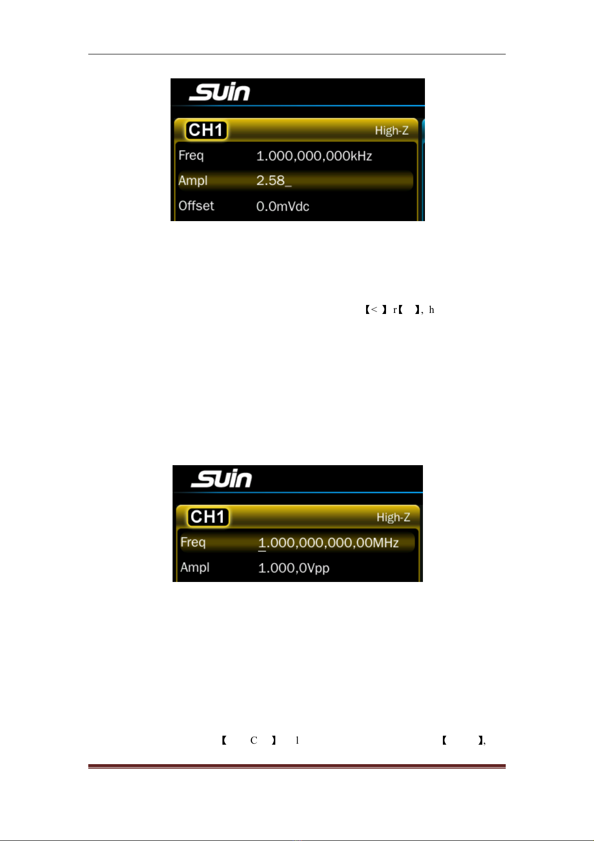
1 4 2 Keyboard input: If one parameter is chosen, the background of chosen item will turn light.
Input data using the Number ke s, decimal point ke and minus ke . If there is mistakes, ou can
press
【
<-
】
to delete one b one before select the unit, or
〖
Cancel
〗
soft ke to cancel the operation.
When the data input is finished, ou should press the unit ke to make the data take effect as
following picture shown.
TFG6800 Series Function/Arbitrar Waveform Generator Users’ Guide
Suin Instruments Co., Ltd 9
Number, decimal point and minus can be onl input b ke board, not b touch screen.
1 4 3 Knobs Adjustment: In the real usage, ou ma have to adjust the signals continuousl , at
this time, ou can use knobs to adjust. When a parameter is chosen, there will be backlight in it,
and also a white line called cursor position under a number. Press
【
<-
】
or
【
->
】
, the cursor position
will move to left or right. While adjust the knob to right, the number with the cursor position will
add one continuousl and can carr up. Adjust the knob to left, the number with the cursor
position will decrease one continuousl and borrow from the high position. Using the knob to
input data, the number will take effect on that it changed, and there is no need to press unit. Move
the cursor position to left, ou can adjust the data roughl , while move it to right, ou can adjust
the parameter detailedl as following shown.
1 4 4 To Select input mode: For the known data, it is more convenient to input b number ke s.
No matter how it changes, it can be input at a time without transitional data generated. For
adjusting the input data or inputting continuousl changing data to observe, using knob is more
easil . Users can choose flexibl according to different requirement.
1 5 Basic Operation
1 5 1 Channel Selection: Press
【
CH1/CH2
】
to select CH1 or CH2 circularl . Press
【
Output
】
, ou

TFG6800 Series Function/Arbitrar Waveform Generator Users’ Guide
Suin Instruments Co., Ltd 10
can turn on or off the output signals from output port in the front panel. The output turns on if the
indicator under the ke light on, while the output turns off if the indicator light off.
1 5 2 To switch parameter setting interface: After enable modulation function, press lighted
button to enter into carrier interface to set. Press
【
Modulate
】
ke again to set wanted modulation
parameter. Press
【 】
when carrier is Sine, while press
【 】
when it’s Square, and press
【
Arb
】
when it’s other waveform. The setting is applied into other function interface switch.
1 5 3 Waveform Selection: There are two waveforms which can be chosen b the ke s directl ,
and the are Sine, Square. Other waveforms need to be selected b pressing
【
Arb
】
, and the are
standard wave, mathematical wave, linear wave, combination wave, window function, special
wave.
Press one of the soft ke s, ou can open the waveform list in this mode.
The selected wave in the waveform list is marked with a little ellow triangle in the left. Switch
the knob to move the little triangle, other waveform will be selected. Press
〖
OK
〗
, the selected
wave will be displa ed in the screen with its name and diagram, at the same time it will be
displa ed in the output port. Press
〖
Back
〗
, return to the function displa . Waveform selection
interface is as following shown:
It is more convenient to select the waveform b touch screen.
1 5 4 Duty cycle setting: If the Square is selected, ou should set the dut c cle to 20% according
to the following steps:
Press
〖
Dut c cle
〗
soft ke , the backlight of it will turn on.

TFG6800 Series Function/Arbitrar Waveform Generator Users’ Guide
Suin Instruments Co., Ltd 11
Press
【
2
】【
0
】
to input the parameter value, press
〖
%
〗
, dut c cle will be 20.0000%, and the
instrument will output the signals according to the new setting.
User can also adjust continuousl dut c cle b using knob and
【
<-
】【
->
】
ke s.
1 5 5 Frequency setting: If ou want to change the frequenc from 1kHz to 2.5kHz, ou can
operate as follows:
Press
〖
Freq/Period
〗
soft ke , select ‘Freq’, the frequenc parameter backlight turns light.
Press
【
2
】【
•
】【
5
】
ke s to input the parameter value, then press
〖
kHz
〗
, frequenc parameter will
be 2.500,000,000kHz. Instrument will output signals according to the setting parameter as below
picture shown:
User can also adjust continuousl frequenc b using knob and
【
<-
】【
->
】
ke s.
1 5 6 Amplitude setting: If ou want to set the amplitude to 1.5Vrms, please operate as follow

TFG6800 Series Function/Arbitrar Waveform Generator Users’ Guide
Suin Instruments Co., Ltd 12
steps:
Press
〖
Ampl/High
〗
, select ‘Ampl’, its backlight will turn light.
Press
【
1
】【
•
】【
5
】
ke s to input parameter value, press
〖
Vrms
〗
, and amplitude will be
1.500,0Vrms. Instrument will output signals according to the setting parameter like below shown:
User can also adjust continuousl amplitude b using knob and
【
<-
】【
->
】
ke s.
1 5 7 Offset setting: If ou want to set the DC offset to -500mVdc, ou can operate as following
steps:
Press
〖
Offset/Low
〗
, select ‘offset’, its backlight will turn light.
Press
【
-
】【
5
】【
0
】【
0
】
to input parameter value, and then press
〖
mVdc
〗
, then offset displa
-500,0mVdc. Instrument will output signals according to the setting as follows shown:
User can also adjust continuousl DC offset b using knob and
【
<-
】【
->
】
ke s.
1 5 8 Amplitude modulation: If ou want to output an amplitude modulation wave, with carrier
wave Sine, 10kHz frequenc , 1Vpp amplitude, 0Vdc offset, 80% modulation depth, 100Hz
modulation frequenc , modulation wave Ramp, ou can operate as following steps:
Press
【
Modulate
】
, then press
〖
T pe
〗
, modulation t pe menu will be displa ed. Press
〖
AM
〗
, wave
diagram will be the modulation wave and modulation menu will be displa ed too.
Press
【 】
to enter carrier wave’s parameter setting, then press
〖
Freq
〗
, set it to 10kHz. Press
〖
Ampl
〗
, set the carrier wave’s amplitude to 1Vpp. Press
〖
Offset
〗
, set carrier wave’s offset to
0Vdc as follows shown:

TFG6800 Series Function/Arbitrar Waveform Generator Users’ Guide
Suin Instruments Co., Ltd 13
Press
【
Modulate
】
again, then press
〖
Depth
〗
to set modulation depth to 80%.
Press
〖
ModFreq
〗
, set it to 100Hz.
Press
〖
Shape
〗
,select
〖
Ramp
〗
, instrument will output the amplitude wave according to the setting
parameter. Details are as follows:
User can also adjust continuousl above modulation parameters b using knob and
【
<-
】【
->
】
ke s.
1 5 9 Sum modulation: If add a Ramp on the output waveform, sum amplitude 50%, please
operate as following steps:
Press
【
Modulate
】
, then press
〖
T pe
〗
, there will be modulation t pe menu displa ed, press
〖
Sum
〗
to select modulation t pe to be Sum, then Sum waveform displa in the diagram area, and
the sum modulation menu will also be displa ed.
Press
〖
Sum Ampl
〗
soft ke to set sum amplitude to 50%.
Press
〖
Shape
〗
to enter wave selection menu. Press
〖
Ramp
〗
to set the modulation wave as Ramp.
Then instrument will output a sum waveform as follows shown:

TFG6800 Series Function/Arbitrar Waveform Generator Users’ Guide
Suin Instruments Co., Ltd 14
User can also adjust continuousl the modulation parameters b using knob and
【
<-
】【
->
】
ke s.
1 5 10 Frequency-Shift Keying Modulation: If ou want to output a frequenc shift ke ing wave,
with hop frequenc 300Hz, frequenc shift rate 50Hz , please operate as following steps:
Press
【
Modulate
】
, then press
〖
T pe
〗
to displa modulation t pe menu, press
〖
FSK
〗
, to set
modulation t pe to be FSK, then frequenc shift ke ing wave will displa in diagram area, and the
frequenc shift ke ing menu will be displa ed too.
Press
〖
Hop Freq
〗
then set it to be 300Hz.
Press
〖
FSK Rate
〗
, set hop frequenc to 50Hz. Instrument will output a FSK wave according to
the setting. Details are as followings:
User can also use knob and
【
<
】【
>
】
ke s to set hop frequenc and frequenc shift rate
continuousl .
1 5 11 Frequency sweep: If output a frequenc sweep wave, of which sweep time 5s, logarithm
sweep, please operate as following steps:

TFG6800 Series Function/Arbitrar Waveform Generator Users’ Guide
Suin Instruments Co., Ltd 15
Press
【
Sweep
】
, mode ‘Sweep’, diagram of frequenc sweep wave and menu will displa .
Press
〖
Sweep Time
〗
, set the sweep time to 5s.
Press
〖
T pe
〗
, set the sweep t pe to Log.
Instrument will output sweep wave according to the setting as follows shown:
1 5 12 Burst output: If output a burst wave, of which burst period 10ms, 5 burst counting c cles,
continuous or single manual trigger, please operate as following steps:
Press
【
Burst
】
, mode ‘Burst’, diagram of burst wave and menu will displa .
Press
〖
Burst Period
〗
, set it to 10ms.
Press
〖
C cle
〗
, set it to 5, while the diagram doesn’t displa the actual period.
Press
〖
T pe
〗
, set it to trigger.
Press
〖
Source
〗
, set it to internal.
Instrument will output the burst wave according to the setting as follows shown:
Press
〖
Source
〗
, set it to manual.

TFG6800 Series Function/Arbitrar Waveform Generator Users’ Guide
Suin Instruments Co., Ltd 16
Press
〖
Manual Trig
〗
per time, instrument will output 5 period waves.
1 5 13 Frequency coupling: If couple the two channel’s frequenc , please operate as following
steps:
Press
【
Multiple Channels
】
to enter the coupling mode and displa the corresponding menu.
Press
〖
FreqCpl
〗
, set it to ‘On’.
Press
【
CH1/CH2
】
to enter continuous work mode. Change CH1’s frequenc value, CH 2’s
frequenc value will change accordingl . Channel 1 and channel 2’s frequenc are equal all the
time. In this time ou can’t set CH2’s frequenc .
Press
【
Multiple Channels
】
, then press
〖
FreqCpl
〗
, set it to Off. In this time, the two channel’s
coupling is disconnected, and returns to mutual independence status.

TFG6800 Series Function/Arbitrar Waveform Generator Users’ Guide
Suin Instruments Co., Ltd 17
Chapter 2 Principle Overview
Through this chapter, ou can get the knowledge of basic concept of signal forming and the
instrument’s internal operation, and then use it better.
2 1 Principle block diagram
After the digit analog converter, two same channels CHA and CHB are separated. Following block
diagram is just one of them.
ADSP
FPGA D/A
Amplitude control
O
ffset control
Reference clock Ke board,
displa and knob
Voltage amplifier
Attenuator Voltage amplifier
Power amplifier
SYNC output
Output port
Output
Protection
Lowpass filtering
FLASH
Programmable
interface
Power Suppl

TFG6800 Series Function/Arbitrar Waveform Generator Users’ Guide
Suin Instruments Co., Ltd 18
2 2 Working principle
2 2 1 Digital combination: To generate a voltage signal, traditional analog generator uses electron
components to constitute oscillator. While its disadvantages are low frequenc accurac and
stabilit , complex technolog , low resolution, not convenient for setting the frequenc and
programming b the computer. DDS is a digital wa of signal generating. It has no oscillator and
uses digit combination to generator a serial of data flow, and then generates an analog signal
through the D/A (digital analog converter).
For example, to generate a Sine, ou should firstl make Y=SinX digital quantification, and then
store X as address and Y as quantification data to waveform memor one b one. DDS uses phase
accumulation technolog to control the waveform memor ’s address. In each sampling clock
period, it accumulates the phase increment to the real time value of the phase accumulator.
Through changing phase increment to change DDS output frequenc value. According to the
address phase accumulator outputs, waveform memor gets out waveform’s quantification data,
and then converts to analog voltage through D/A and operational amplifier. Waveform data is
discontinuous sampling data, what DDS generator outputs is a staircase sine waveform. Higher
harmonic in the waveform has to be filtered b low pass filter (LPF), after that the outputs is
continuous sine wave.
2 2 2 Working principle: There is a high resolution digital analog converter(D/A) inside device,
which uses high accurac reference voltage source to provide reference voltage which can be set
for amplitude and offset control, thus we guarantee output amplitude’s and DC offset’s accurac
and stabilit .
After amplitude and offset controlling, the signals will go through attenuator, voltage amplifier
and power amplifier, and then be output b output interface.
Microcontroller (ADSP) controls ke board and displa ing, when the ke s are pressing, it will
recognize the code and then execute it. The displa circuit will displa instrument’s working status
and various parameters.
The knob in the front panel is used for changing the number in cursor position. Ever rotating to
an angle there will be a trigger pulse generating. Controller can judge whether it is left or right
rotating, if it is left rotating, the number in cursor position will be decreased one; if it is right
rotating, the number will increase one, and carr or borrow a bit continuousl .

TFG6800 Series Function/Arbitrar Waveform Generator Users’ Guide
Suin Instruments Co., Ltd 19
Chapter 3 Operating Instruction
This chapter will introduce instrument’s function characteristic and operation in detail. Before
reading this chapter, if ou haven’t master instrument’s basic operation, firstl please read chapter
1 Quick Start and make more practice. In this chapter, we will not repeat the basic operation and
mainl take CH1 as example in the operation of this chapter because other channel’s setting is
totall same as CH1’s.
3 1 Working Mode
Multi working modes are configured into instrument, each channel is independent, with same
characteristic.
3 1 1 Continuous output: select continuous mode to output continuous signals.
3 1 2 Modulation output: it can output modulation signals, such as FM, AM, PM, PWM, SUM,
FSK, PSK, ASK, OSK, etc.
3 1 3 Frequency sweep: Linear and Log sweep are supported.
3 1 4 Burst output: it can output burst signals with specified c cles.
3 1 5 Double Pulse: it can output double pulse signals.
3 1 6 Arbitrary waveform: it can output user defined arbitrar waveform.
3 1 7 Waveform’s sequence: it can output wave sequence user defined.
3 1 8 Frequency sequence: it can output FH signal user defined .
3 1 9 Harmonic Synthesis: it can output multiple harmonic signal user defined.
3 1 10 Parameter coupling: To couple the parameter’s setting between channels
3 2 Continuous Output
Continuous output means that output signals are stable and continuous. Signal’s waveform,
frequenc and amplitude don’t change with time, while signal’s phase changes linearl with time.
3 2 1 Waveform selection: There are 165 kinds of built-in waveform as following:
No Waveform No Waveform
Standard Waveform 7
Table of contents
Other Suin Portable Generator manuals

Popular Portable Generator manuals by other brands


AIE
AIE SQ Series manual

Airthereal
Airthereal MA10K-PRO user manual

Jupiter Avionics
Jupiter Avionics JA37-300 Installation and operating manual

Briggs & Stratton
Briggs & Stratton 30238 owner's manual

Husqvarna
Husqvarna 420 GN Illustrated parts list

Champion Power Equipment
Champion Power Equipment 75531i Owner's manual & operating instructions


