Suitmate Swimsuit Water Extractor User manual

1
© October 1997 Extractor Corporation. All rights reserved.
The SUITMATE®Swimsuit Water Extractor has been designed and manufactured with
safety as our primary consideration. Therefore, it is important that the unit be installed
correctly. It is also important that the installation comply with all local building codes
and regulations. Please consult your local licensed plumbing and electrical engineers
or contractors about your installation. Read the entire INSTALLATION instructions before
beginning your installation. Remember:
DO IT RIGHT
and
DO IT SAFE.
PROPER LOCATION FOR THE SUITMATE
Following is a list of factors to consider in determining a location for the SUITMATE.
1. The unit should be located in an area that is near where people remove and rinse
out their swimsuits.
2. The unit should NOT be located in a cluttered area or where it is exposed to direct
shower water or water hose down.
3. The unit should be mounted on a wall structure that will support the unit’s approxi-
mate 60 pounds hanging weight plus the added weight or pressure of people
leaning on the unit. Consult the PROPER WALL MOUNTING section of these
instructions to determine an appropriate location.
4. There should be a means to dispose of the waste water from the unit. Consult the
PROPER DRAINAGE section of these instructions to determine an appropriate
location.
5. The unit should be wired to a 120 volt 20 ampere 60Hz
dedicated circuit
. Consult
the PROPER ELECTRICAL CONNECTIONS section of these instructions to deter-
mine an appropriate location.
PROPER WALL MOUNTING OF THE SUITMATE
The SUITMATE should be mounted to the wall with the Mounting Bracket that is provided
with the unit. The SUITMATE INSTALLATION TEMPLATE shows the recommended location
for the mounting holes, the electrical service, and the waste water outlet (if utilized). The
SUITMATE Mounting Bracket must be secured to a wall stud, or to a concrete block or
cinder block wall.
Anchors in drywall are not sufficient to mount the SUITMATE.
Locating and Securing the
Mounting Bracket to the Wall
The recommended height from the floor to the top of
the SUITMATE is 42 inches. At least an additional
10 inches of clearance above the SUITMATE is needed
for the opening and closing of the Lid. This means that
the top edge of the Mounting Bracket should be 391⁄2
inches from the floor. Use the SUITMATE INSTALLA-
TION TEMPLATE to determine a location on the wall
that provides for adequate clearance, a strong and
secure place for the Mounting Bracket as well as easy
access to the electrical and drainage connections.
The Mounting Bracket must be level after secured to the wall.
WARNING
WARNING
INSTALLATION 120 Volt 20 ampere 60 Hz
CHECK WITH LEVEL
TO
WALL
LAG
SCREWS
MOUNTING SCREWS
MOUNTING
BRACKET

2
© October 1997 Extractor Corporation. All rights reserved.
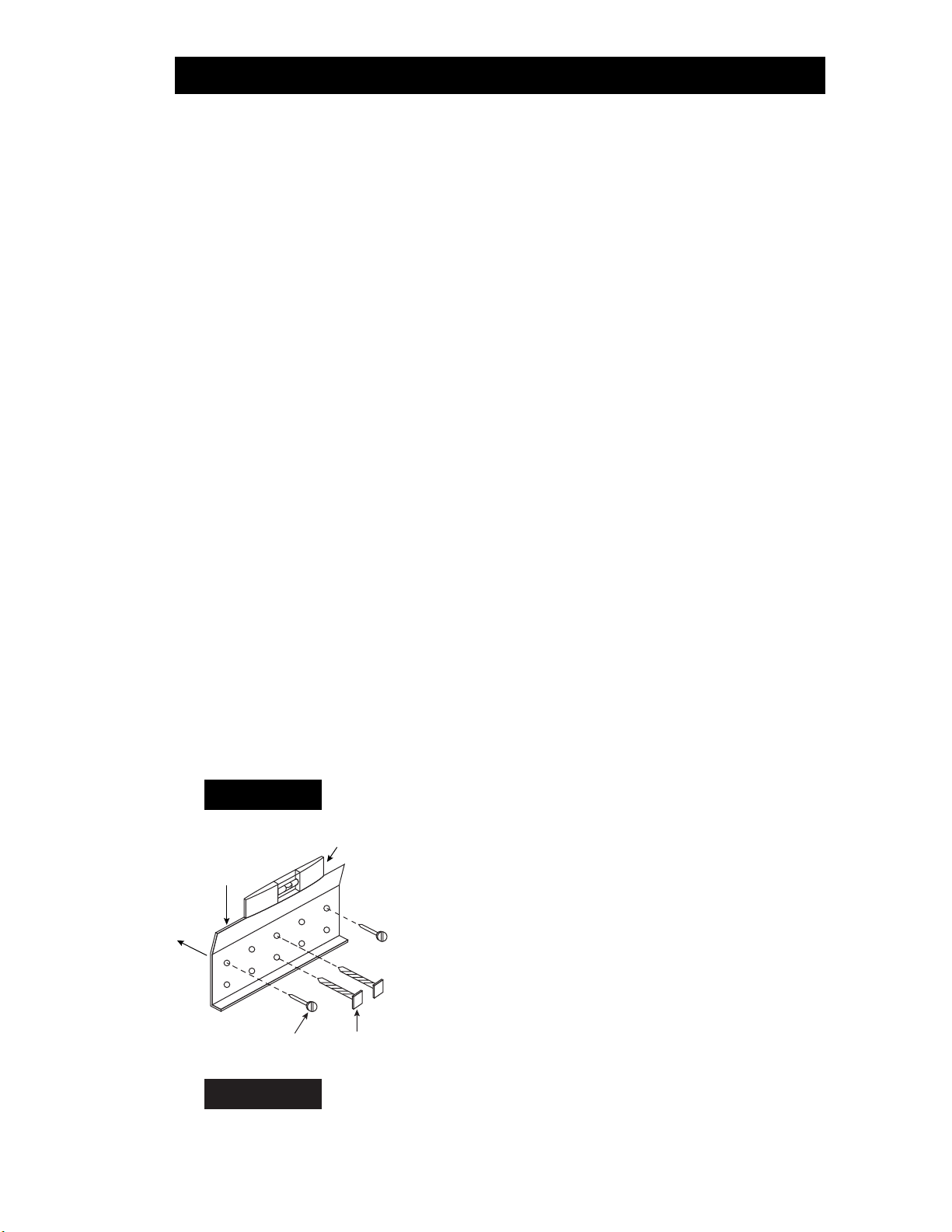
To secure the Mounting Bracket to a stud, center the Bracket on the stud and mark on
the wall or the stud the location of the two vertical center holes of the Mounting Bracket.
Drill the marked locations with a 1⁄8inch drill bit. Make sure the Mounting Bracket will
be level after it is secured to the wall. Reposition the Mounting Bracket over the two
marked center holes and mark at least one additional hole on each side of the center
holes. Drill the outer two holes to receive wall anchors. Install the wall anchors.
Secure the Mounting Bracket to the stud by using two 5⁄16 x 2 inch lag screws through
the two vertical center holes. Make sure the Bracket is level. Finish securing the Bracket
with the appropriate fasteners in the outer two holes. For mounting to concrete, etc.,
use at least four No.10 or larger screws fastened into appropriate anchors. After the
Bracket has been anchored to the wall and the electrical and drainage requirements
have been allowed for, the SUITMATE is ready to be mounted to the wall.
Mounting the Suitmate to the Wall
Remove all packaging material from the SUITMATE
including material around the Motor and the shipping
board on the bottom of the unit. The upper back lip of
the SUITMATE should be lowered down and centered
on the Bracket. After the unit is centered, push down
on the back of the unit to make sure that it is securely
wedged onto the Bracket. Make sure the unit is level.
If it is not level, remove the unit, adjust the Mounting
Bracket and re–hang the unit. A level installation is
necessary to minimize vibration and insure proper
drainage of waste water. Using appropriate fasteners
and anchors on the lower mounting channel at the
bottom rear of the unit, finish securing the unit to the
wall. This will prevent the unit from being lifted from
the Bracket or being moved.
PROPER DRAINAGE FOR THE SUITMATE
Note:
Strictly follow all applicable local plumbing codes and regulations.
To a Floor Drain
Drainage of the waste water to a floor drain should be done
ONLY
in an area where
the floor is normally wet.
DO NOT
drain water across a floor where people do not
expect to encounter a wet and slippery condition. SUITMATE comes with a short
flexible floor drain extension tube connected with a stainless steel hose clamp to its
drain tail piece.
The drain tube that comes with the unit must not be removed unless the
unit is connected to an approved waste water outlet or the factory supplied
tube is replaced with another tube according to the following instructions.
Replacing the Factory Drain Tube with a Longer Drain Tube
Use a 11⁄4inch I.D. drain tube with a smooth interior that will not crimp or collapse.
Use the stainless steel hose clamp that is provided with the factory flexible floor drain
extension tube to secure the replacement tube to the unit’s drain tail piece. Run the
drain tube so that it is never higher than the bottom of the SUITMATE and always
slopes down. Secure the drain tube to the wall or floor with properly sized “U” clamps
so it cannot be maneuvered to trap waste water. Cut off the end of the drain tube on
an angle to help prevent it from being blocked by the floor, wall, or some other object.
Upon completion of the installation, check to make sure that there is a free flow of
water from the drain tube extension.
WARNING
PRESS HERE TO
FIRMLY SET SUITMATE
MOUNTING
SCREWS
CUTAWAY VIEW OF UNIT
LOWER
MOUNTING
CHANNEL
UPPER
BACK LIP
WALL
MOUNTING
BRACKET
WALL
FLOOR
EASE UNIT
OVER
BRACKET
AND
LOWER

3
© October 1997 Extractor Corporation. All rights reserved.
To an Approved Sanitary Waste Line
This installation should only be done in accordance with all applicable local plumbing
codes and regulations. The unit’s 11⁄4inch O.D. drain tail piece is designed for connec-
tion with standard compression type plumbing fittings. There is room inside the hous-
ing for the use of a standard “P” type plumbing connection. The waste outlet should be
located in the wall behind the unit. The SUITMATE INSTALLATION TEMPLATE shows
the appropriate location for the waste outlet.
If an open-site drain connection is required
and the open site is to be positioned within
the SUITMATE housing, locate the top of the
receiver pipe below the top of the Motor
end cap, and locate the top outer edge of
the receiver pipe at least 11⁄4inch from the
body of the Motor. (See also the SUITMATE
INSTALLATION TEMPLATE.) Be sure that the
cut off end of the drain extension tube is
below the top of the receiver with the angle
cut facing away from the Motor as illustrated.
PROPER ELECTRICAL CONNECTIONS FOR THE SUITMATE
Note:
Strictly follow all applicable local electrical codes and regulations.
SUITMATE is equipped with a ground fault circuit interrupter (GFCI) and is designed
to be connected to a 120 volt 20 ampere 60Hz
dedicated circuit
that is protected
by a fuse or circuit breaker.
A PLUG–IN INSTALLATION IS NOT ACCEPTABLE
. The
utilized circuit must be run to the SUITMATE weatherproof Junction Box which contains
CUSTOMER’S ELECTRICAL SERVICE
120V—20AMP—60HZ
GROUND
HOT WHITE
HOT WHITE
GREEN
SCREW
GFCI
LOAD
GFCI IS
“GROUND FAULT CIRCUIT INTERRUPTER”
MOTOR CONTROLLER AND SWITCH
RED RESET BUTTON, ON
BLACK TEST BUTTON, OFF
REMOTELY ACTUATED MICROSWITCH
TRIPPED AND HELD CLOSED BY
USER HAND PRESSURE ON SUITMATE LID
DRIVE MOTOR
TERMINAL STRIP
L1 A B L2
GREEN SCREW
LID OPEN
SWITCH STATUS SHOWN
SUITMATE
HOT NEU
SUITMATE HOUSING
MOTOR
HOUSING
MOTOR
END CAP MIN.
1–1/4"
SUITMATE
TAILPIECE
ANGLE CUT
EXTENSION
TUBE
TO DRAIN

4
© October 1997 Extractor Corporation. All rights reserved.
the GFCI. A liquid tight raceway such as Ultralight®Liquid Tight Flexible Conduit (or
its equivalent) should be used from the circuit connection to the Junction Box. The
SUITMATE INSTALLATION TEMPLATE shows the location of the suggested area behind
the unit for the entrance of the electrical raceway that does not interfere with the
drainage connection.
Do not route the raceway where waste water can flow or drip on it.
Remove the cover of the weatherproof Junction Box which contains the GFCI and
remove the GFCI mounting screws. The circuit ground conductor must be connected
to the green grounding screw located on the GFCI. If no ground is available on the
circuit utilized, you
must provide
a proper ground for the SUITMATE. The hot and
neutral leads of the power circuit should be connected to the GFCI screw terminals
marked “LINE”. Connect the hot lead to the terminal marked “HOT” and the neutral
lead to the terminal marked “WHITE”. After the correct electrical connections have
been properly made, remount the GFCI using the screws previously removed. Reinstall
the weatherproof Junction Box cover previously removed. This cover provides access
to the GFCI “TEST” and “RESET” buttons.
POSTING THE WALL SIGN
It is important that the wall sign included in the INSTALLATION PACKAGE be mounted
on the wall above the unit. Locate the bottom edge of the sign six inches above the
SUITMATE. At this height the sign will not be blocked when the Lid is raised. It will also
serve as a stop to keep the Lid from striking the wall behind the unit.
The sign has an adhesive foam strip around the perimeter of the back side. Be sure the
surface that the sign is to be mounted to is clean and dry. Peel off the protective strip
to expose the adhesive foam. Without touching the sign to the wall, align the sign six
inches above the unit and at its center. Press the sign to the wall and rub firmly over the
adhesive portion of the sign.
TESTING AND OPERATION
After the mounting and all connections are complete, test the SUITMATE as follows:
1. Make sure all packaging material is removed from the unit including material
around the Motor and the shipping board on the bottom of the unit.
2. Check to see that the Basket is empty and that the Lid moves freely.
3. Press down on the Lid and hold down for several seconds. The unit should run
smoothly and there should be no excessive vibration or noise.
4. Release and lift the Lid from the down position. The Basket should stop rotating
within a second or two.
5. Test the SUITMATE by putting a wet swimsuit in the unit according to the instruc-
tions on the underside of the Lid. If there is excessive vibration or noise it is
usually caused by the improper loading of the swimsuit. Be sure that the swimsuit
is pushed to the bottom of the Basket and that all material is at least two inches
below the top of the Basket.
WARNING

5
© October 1997 Extractor Corporation. All rights reserved.
INSTALLATION TROUBLESHOOTING
If the SUITMATE does not operate, check the following:
1. Check to see if there is power to the unit. Check the circuit using an A.C. voltmeter
set to the appropriate range; measure across the “LINE” side of the GFCI.
2. Make sure that the GFCI switch is in the “ON” position. The red button must be
depressed to turn on the GFCI.
3. Check the connections in the GFCI Junction Box. Be sure there is power on the
“LOAD” side of the GFCI.
4. Check the SUITMATE TROUBLESHOOTING section in this manual for additional
troubleshooting assistance.
FINISHING THE INSTALLATION
Be sure to save this SUITMATE MANUAL along with all the other materials included in
the INSTALLATION PACKAGE envelope. If you did not receive all the materials listed
or need additional information, call the Extractor Corporation at 800–553–3353.
With proper installation, use, and maintenance your SUITMATE®Swimsuit Water
Extractor will provide you with years of trouble–free service.
Other manuals for Swimsuit Water Extractor
2
Table of contents
Other Suitmate Ventilation Hood manuals
Popular Ventilation Hood manuals by other brands

hestan
hestan KVL Series Installation use and care manual

KOBE
KOBE IN-027 Series Installation instructions and operation manual

Franke
Franke FDL 662 XS installation manual

Lapetek
Lapetek APOLLO-V X1 Installation and user manual

Monogram
Monogram ZVB36 owner's manual

KKT KOLBE
KKT KOLBE Profi Series user guide

ROSIERES
ROSIERES CBT6130/3X instruction manual

Miele
Miele DA 7090 W Operating and installation instructions

AEG
AEG DGK6981HM user manual

KOBE
KOBE Brillia CHX2224SQB-1 Installation instructions and operation manual

Faber
Faber V-AIR installation manual

Siemens
Siemens LC64PBC50 Instructions for installation and use