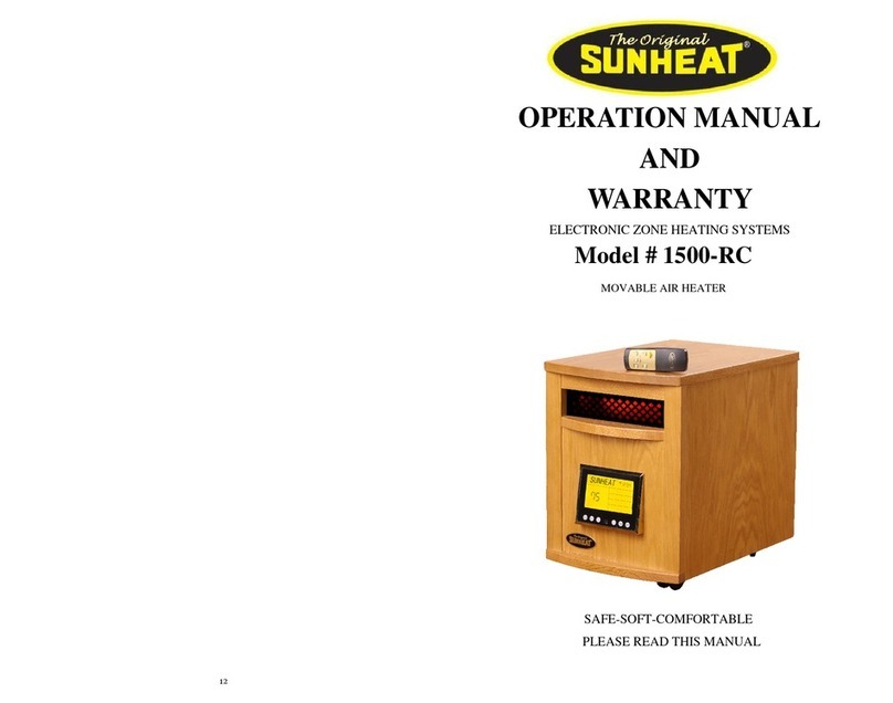
Sun Heat Thermal Wave F15 Assembly instructions

THERMAL WAVE F15
Repair Guide
!! Unplug The Heater Before Servicing!!
(Remember That The Edges Of The Metal Are Sharp. Use Caution)
A. How To Remove Center From The Wood Mantle
B. How To Remove Center Top Cap
C. How To Remove Front Glass
D. How To Remove Fire Log Set & Firelight Screen
E. How To Replace Quartz Infrared Heating Elements
F. How To Replace High Limit Switch

G. Replace Heat Exchanger Circulation Fan
H. Replace Circuit Board
I. Replace Display Screen
J. Replace Air Temperature Sensor
K. Replace Flame Effect Light Bulb
L. Replace Flame Effect Light Bulb Sockets
M. Replace Fire Light Drive Rod Motor
N. Replace Power Cord
O. Wiring Diagram
PLEASE CALL CUSTOMER SERVICE
FOR ASSISTANCE:
1-877-467-8643

A
How To Remove Center From The Wood Mantle
!! Unplug The Heater Before Servicing!!
(Remember That The Edges Of the Metal Are Sharp. Use Caution)
Remove the 5 screws securing the center to the back bracket plate. Note: You do not have to
remove the 4 screws securing the plate to the cabinet. You will leave this plate attached to the
cabinet when center is removed.

A
Clip zip tie securing temperature sensor in place.
Take care not to clip the temperature sensor wire.
Remove the 4 screws located on the bottom of the cabinet. Then remove the center by sliding it
out the front of the cabinet. Note: Be careful to protect the lower lip of the mantle.
There are screws on the bottom of the metal center that could cause damage to the
finish.

B
How To Remove The Center Top Cap
!! Unplug The Heater Before Servicing!!
(Remember That The Edges Of the Metal Are Sharp. Use Caution)
Remove the 2 perimeter screws located on each side of top cap. Remove the 4 perimeter screws
that are located on the top of the top cap. The cap will then slide off.

C
How To Remove Glass
!! Unplug The Heater Before Servicing!!
(Remember That The Edges Of the Metal Are Sharp. Use Caution)
Remove the 4 perimeter screws on each side of the center. The whole front section will then
come off in one piece.

C
Once the front panel is removed, you are able to gain access to the 3 screws securing the “L”
bracket into place. Remove those 3 screws.
Gently push the glass from the outside and it will come out of the channel.

D
How To Remove Fire Log Set & Fire Light Screen
!! Unplug The Heater Before Servicing!!
(Remember That The Edges Of the Metal Are Sharp. Use Caution)
Remove the 4 screws that hold the fire log set in place. There are 2 screws at each end of the
fire log set. These screws are accessed through holes in the metal case (See Screw Locations
Below).
With a utility knife cut the caulking out from the bottom of logs.
NOTE: The log set is made out of fiberglass. Applying excessive force may cause
damage.
Screws

D
Remove the 6 screws that hold the fire light screen into the fireplace (See Screw Locations
Below).
Removing the fire light screen will give access to the fire light drive rod and drive rod motor.
Screws
Bulb Sockets
Drive Rod
Drive Rod Motor

E
How To Replace Quartz Infrared Heating Elements
!! Unplug The Heater Before Servicing!!
(Remember That The Edges Of the Metal Are Sharp. Use Caution)
After determining which of the 3 heating elements has failed, remove the 2 screws holding the
heating element access plate in place.
**ALLOW ELEMENTS TO COOL BEFORE REMOVING**
Trace the heating element wire back to the circuit board and remove both connections. Remove
the malfunctioning heating element out of the heat exchanger and replace. Make sure to plug
both connects back into the circuit board.
Heat Exchanger Box
Heating element access plate

F
How To Replace High Limit Switch
!! Unplug The Heater Before Servicing!!
(Remember That The Edges Of the Metal Are Sharp. Use Caution)
The High Limit Switch is located on the right side (by the display screen) of the heat exchanger
box. Remove the 1 anchor screw that holds the High Limit Switch in place. Remove the 2 wire
leads from the old switch and replace. They attach to WK-1 and WK-2 on the circuit board.
High Limit Switch
Wire Leads
Anchor Screw

G
How To Replace Circulation Fan
!! Unplug The Heater Before Servicing!!
(Remember That The Edges Of the Metal Are Sharp. Use Caution)
To gain access to the circulation fan, the heat exchanger box must be removed from the
fireplace. Remove the 4 anchor screws that hold the heat exchanger assembly in place. There
are 2 screws on each side of the heat exchanger.
Heat Exchanger
Fan
2 screws will be located on each side of Heat Exchanger

G
To Remove Fan, locate the 4 screws on the top of exchanger which hold the fan in place. They
are the 4 screws closest to the Fan.
Note: The bottom of the exchanger has a black plate attached.
Trace the 2 wires connected to the fan on the circuit board. They are AC-N1 and FAN.
Note: These wires are universal and it will not matter which terminal they connect
to.
Top
Bottom
Fan

H
How To Replace Circuit Board
!! Unplug The Heater Before Servicing!!
(Remember That The Edges Of the Metal Are Sharp. Use Caution)
Remove the Circuit Board by removing all 4 screws that hold it in place. These screws are
located on each corner of the board.
NOTE: Keep wires attached to old board
Put the new board in place. Disconnect 1 wire at a time from old board and connect it to the
appropriate location on the new board.
**If you disconnect all wires at once, please refer to wiring diagram (O) for wire
location.
MAKE SURE THE TEMPERATURE SENSOR AND DISPLAY SCREEN ARE
PLUGGED BACK INTO THE CIRCUIT BOARD.
Temperature Sensor Plug
Display Plug
Screw Location
Screw Location

I
How To Replace Display Screen
!! Unplug The Heater Before Servicing!!
(Remember That The Edges Of the Metal Are Sharp. Use Caution)
Remove the 2 screws holding the access panel in place and unplug Display Screen from the
Circuit Board.
Push up on the bottom of the screen and pull it out the front.
****MAKE SURE THE DISPLAY SCREEN IS PLUGGED BACK INTO CIRCUIT BOARD.

J
How To Replace Air Temperature Sensor
!! Unplug The Heater Before Servicing!!
(Remember That The Edges Of the Metal Are Sharp. Use Caution)
The air temperature sensor is located on the back side of fireplace. Pinch both sides of the
grommet together and push it out to free the temperature sensor from its location.
Replace with new temperature sensor and make sure it is plugged in to circuit board.
(leave temperature sensor sticking out about an inch)
Temperature
Sensor Plug
Temperature Sensor

K
How To Replace Flame Effect Light Bulb
!! Unplug The Heater Before Servicing!!
(Remember That The Edges Of the Metal Are Sharp. Use Caution)
Remove the 6 screws securing the access panel to the back of the heater and you will be able to
see the bulb. Note: The bulbs are a standard 40 watt utility bulb.
Remove the wire connection securing the bulb in place.

L
How To Replace Flame Effect Light Bulb Sockets
!! Unplug The Heater Before Servicing!!
(Remember That The Edges Of the Metal Are Sharp. Use Caution)
The bulb sockets have to be replaced together. You can gain access to the bulbs sockets 2
ways.
1.) Remove access panel on the back
2.) Remove the Glass, Logs and Fire Screen
Once you have gained access to the sockets, remove the wire connection and bulb. Hold the
base of the bulb socket with one hand while unscrewing the anchor ring.
Run the wire up to the circuit board. The wires will attach to AC-N5 and LAMP on the circuit
board.
Note: These wires are universal and it will not matter which terminal they connect
to.
Anchor Ring
Base of the Bulb Socket

M
How To Replace Fire Light Drive Rod Motor
!! Unplug The Heater Before Servicing!!
(Remember That The Edges Of the Metal Are Sharp. Use Caution)
To gain access to the drive rod motor, remove the front panel (glass), logs and fire screen. Then
remove the 6 screws on the bottom of the center portion that mount the drive rod brackets in
place. There are 3 screws on each side. After gaining clear access to the fire light drive rod
motor, use a pair of pliers to hold the nut end while you use a screwdriver to unscrew the other
end. Trace the wires to the appropriate location on the circuit board.
The yellow wire plugs into SWING. The white wire plugs into AC-N6.
Drive Rod Mounting Brackets

N
How To Replace Power Cord
!! Unplug The Heater Before Servicing!!
(Remember That The Edges Of the Metal Are Sharp. Use Caution)
Using a pair of pliers, either squeezes the inside or the outside of the grommet to pull it
through the grommet hole. Remove old power cord. Attach new power cord to circuit board.
Note: These wires are universal and it will not matter which terminal they connect
to.
1 wire connects to AC-L. The other wire connects to AC-N.
Table of contents
Other Sun Heat Heater manuals
Popular Heater manuals by other brands

Timberk
Timberk TOR 21.1206 BC instruction manual

Spacio Innovations
Spacio Innovations WEXSTAR WS-4W installation instructions

Sealey
Sealey IRC153.V4 instructions

Perel
Perel CH0003 user manual

Star Progetti
Star Progetti Varma Tec VARMA HOME operating instructions

HSC
HSC Elite BH25V2 operating instructions