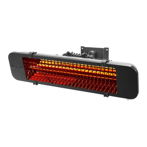
Barton 96053C Original instruction manual

OWNER’S MANUAL AND SAFETY INSTRUCTIONS
SAVE THIS MANUAL. KEEP THIS MANUAL FOR SAFETY WARNINGS, PRECAUTIONS, ASSEMBLY,
OPERATION, INSPECTION, MAINTENANCE AND CLEANING PROCEDURES. WRITE THE PRODUCT’S
SERIAL NUMBER ON THE BACK OF THE MANUAL, OR THE MONTH AND YEAR OF PURCHASE IF
PRODUCT HAS NO SERIAL NUMBER
FOR QUESTIONS, PLEASE CALL CUSTOMER SERVICE: 909.628.4900
1500W LAMP HEATER
ITEM # 96053C (BRONZE ), 96054C ( MOCHA)

SAFETY INFORMATION
Read all safety warnings and instrucons. Failure to follow the warnings and instrucons may result in
injury and/or property damage. Save all warnings and instrucons for future reference.
The warning and safety instrucons in this manual are not meant to cover all possible condions and
situaons that may occur. Common sense, cauon and care must be exercised when operang or
cleaning tools and equipment. Always contact your dealer, distributor, service agent or manufacturer
about problems or condions you do not understand before operang the product.
1
WARNING: This heater is not equipped with a device to control the room temperature. Do not use this
heater in small rooms when they are occupied by persons not capable of leaving the room on their
own, unless constant supervision is provided.
Failure to comply with the precauons and the instrucons provided with this heat lamp can result in
death, serious injury and property damage or loss from hazards of re, explosion and burns.
During operaon, this product can be a source of ignion. Keep the heater area clear and free from
combusble materials, gasoline, solvents, paint thinner, cleaning solvents and other ammable vapors
and liquids.
Minimum heater clearances from combusbles is three feet from the sides and two feet from the top
of the heater.
NEVER operate this device with the protected heang element opening blocked. Keep this opening
free of lint, hair, etc. Never operate on or near a so surface such as a pillow, blanket, or bed where
this air opening may be blocked.
NEVER store propane near high heat, open ames, pilot lights, direct sunlight, other ignion sources
or where temperatures exceed 120 degrees F.
Propane vapors are heavier than air and can accumulate in low places. If you smell gas, leave the area
immediately.
NEVER install or remove propane cylinder while the heater is lit, near ame, pilot lights, other ignion
sources or while the heater is hot to the touch.
Store the propane cylinder outdoors in a well venlated space out of reach of children. NEVER store
the propane cylinder in an enclosed area. If storing indoors, disconnect the cylinder.
This heater is not intended for use in bathrooms, laundry areas and similar indoor locaons. NEVER
locate heater where it may fall into a bathtub or other water container. To protect against electrical
hazards, DO NOT immerse in water or other liquids.
Check with your local re safety authority if you have quesons about heater use. Other standards
govern the use of fuel gases and heat producing products for specic uses. If no local codes exist,
follow the Naonal Fuel Gas Code, ANSI Z223.1.

SAFETY INFORMATION SAFETY INFORMATION
2
SAVE THESE WARNINGS
This heater is a combuson appliance. All combuson appliances produces carbon monoxide (CO)
during the combuson process. This product is designed to produce extremely minute, non-hazardous
amounts of CO. DO NOT block air ow into or out of the heater.
For outdoor use ONLY. NEVER use inside enclosed, non-venlated areas.
If you smell gas: 1. Shut o gas to the appliance. 2. Exnguish open ame. 3. If odor connues,
immediately call your gas supplier.
Keep all connecons and ngs clean. Make sure propane cylinder valve outlet is clean.
Inspect hose before use. Replace if there is evidence of abrasion or wear.
During set up, check all connecons and ngs for leaks using soapy water. NEVER use a ame.
ALWAYS place the heater on a at, level surface. Use as a heang appliance only. NEVER alter in any
way or use with any device.
WARNING: This product is fueled by propane gas. Propane gas is invisible, odorless, and ammable.
An odorant is normally added to help detect leaks and can be described as a “roen egg” smell. The
odorant can fade over me so leaking gas is not always detectable by smell alone.
Propane gas is heavier than air and leaking propane will sink to the lowest level possible. It can ignite
by ignion sources including matches, lighters, sparks or open ames of any kind many feet away from
the original leak. Use only propane gas set up for vapor with draw.
Propane gas should be stored or used in compliance with local ordinances and codes or with ANSI/
NFPA 58. Turn o propane when not in use.
NEVER install or remove propane cylinder while heater is lighted, near ame, pilot lights, other ignion
sources or while heater is hot to touch.
The propane cylinder must always be stored outdoors in a well venlated space. NEVER store propane
cylinder in an enclosed area (house, garage, etc.). If heater is to be stored indoors, disconnect the
propane cylinder for outdoor storage.

PACKAGE CONTENTS
1 2

ASSEMBLY
2
PREPARATION
Before beginning assembly, make sure all parts are present. Compare all parts against the contents list
and hardware are represented in the contents. If any parts are missing or damaged, do not aempt to
assemble the heater. Contact customer service for replacement parts.
Tools required for assembly, not included:
• Phillips screwdriver with medium blade • Leak test soluon
ATTACHING THE ANCHORING ARM:
Aach one anchoring arm to the base with 2
screws and nuts as shown. Repeat with the other
2 anchoring arms so all three are aached to the
base.
To anchor the heater to the ground, insert anchoring
[ins through the anchoring arms and directly into
the ground as shown.
STEP 1: Aach wheel assemble Kto base J. Align holes in
the wheel assembly with corresponding holes in the base
and insert 2 medium bolts through the holes and nger
ghten. Conrm that the wheel assembly is parallel to the
base Jand ghten with a wrench.
Hardware used: 2 x medium bolts
STEP 2: Aach the post supports Ito the base J. Align the
holes in the boom of each post support with the hole
on the base. Insert 1 medium bolt through the hole in the
support and into the base and hand ghten. Repeat with
the other 2 post supports and ghten bolts with a wrench.
Hardware used: 3 x medium bolts
STEP 3: Aach the lower post Gto the post supports I. Once
you have ghtened the bolts holding the post supports I
to the base J. Align the holes in the lower post Gwith the
holes on the tops of the post supports and inset a large bolt
through the hole in the post support. Secure with a small
ange nut. Repeat this with in the 5 remaining holes. (6
holes total. 2 for each post support piece). Hand ghten
with the wrench when all bolts have been inserted.
Hardware used: 6 x large bolts | 6 x small ange nuts

ASSEMBLY
1 2
STEP 4: Aach upper post Fto lower post Gby screwing the
two pieces of the post together.
Hardware used: 3 x Reector studs | 3 x Large at washers
STEP 5: Slide tank housing D over the assembled upper/
lower posts F/G and down over the post supports I. Rest
the tank housing on the base J.
STEP 6: Aach the reector studs to the top of the head
assembly C. Insert 1 reector stud through 1 large at
washer and into the hole on top of the head assembly C.
Tighten stud securely. Repeat with the other 2 reector
studs.
Hardware used: 4 x small bolts with lock washers
STEP 7: Aach head assembly Cto upper post F. Loosen or
remove the 4 small bolts with lock washers pre-installed in
the neck of the head assembly. Route the gas hose E down
into the upper/lower posts F/G and align 4 small holes on
the head assembly Cwith the four small holes in the upper
post F. Insert 4 small bolts with lock washers through the
aligned for holes and ghten securely with a wrench.

ASSEMBLY
2
STEP 8: Install reector, note: make sure to remove plasc
cover on the reector pieces prior to assembly.
Assembly Tip: If necessary for proper alignment of reector
secons, loosen each screw prior to further assembly and
re-ghten aer secons are aligned.
Slide two Reector Panels Atogether. insert one small
screw. Screw on cap Nut loosely. Repeat with the other
reector panels A.
Slide reector center cap B onto assembled reector
panels A. Insert one small screw and screw the cap nut
loosely. Repeat with two more small screws and cap nuts
to complete reector assembly. Fully ghten all screws and
cap nuts.
Hardware used: 6 x Large at washers | 3 x Wing nuts
STEP 9: While supporng heater, lt the head assembly C
and slide 3 large at washers over the reector studs. Place
the reector assembly onto the reector studs and onto the
reector assembly. Secure with 3 wing nuts. Once you have
ghtened the wing nuts, return the heater to an upright
STEP 10: Connect the hose and regulator to the LPG tank.
The LPG tank is sole separately. Use a standard 20lb propane
tank only. Li the Tank Housing Dup and rest it on the top of
the assembled post supports I. Screw the regulator Honto
the Gas Hose E. Do not cross thread. Aach the regulator to
the valve on the LPG tank and hand ghten securely. Place
LPG tank onto the base of the heater. Secure the LPG tank
by aaching the Chain L onto the post supports. Lower the
tank housing.
NOTE: Use the heater only with a propane vapor withdrawal
supply system. See “Standard for storage and handling of
liqueed petroleum gas, ANSI/NFPA 58. Your local library
and/or re department should have this book.

OPERATION
1
The installaon must conform with local codes or in the absence of local codes go by the Naonal Fuel
Gas Code ANSI Z223.1/NFPA54 natural gas and propane installaon code CSA 8149.1 or propane storage
and handling code B149.2 A
dented, rusted or damaged propane cylinder may be hazardous and should be checked by your local
cylinder supplier. Never use a propane cylinder with a damaged valve connecon. The propane cylinder
must be constructed and marked in accordance with the specicaons for LPG tanks of the US Department
of Transportaon (DOT) or the standard for cylinders, spheres and tubes for transportaon of dangerous
goods and commission. CAN/CSA-B339.
• The cylinder must have listed overlling prevenon device
• The cylinder must have a connecon device compable with the connecon for the appliance
• The cylinder used must include a collar to protect the cylinder valve
• Never connect an unregulated propane cylinder to the heater
• Do not store a spare LP gas cylinder under or neat this appliance
• Never ll the cylinder beyond 80% full
• Place the dust cap on the cylinder valve outlet whenever the cylinder is not in use
• Only install the type of dust cap on the cylinder valve that is provided with the cylinder valve. Other
types of caps or plugs may result in leakage of propane.
LEAK TEST
1. Make 2-3oz of test soluon: One part dish soap and three parts water.
2. Apply several drops of soluon where hose aaches to the regulator.
3. Apply several drops of soluon where the regulator connects to the cylinder.
4. Make sure the heater valves are o.
5. Turn the cylinder valve on.
IF BUBBLES APPEAR AT ANY CONNECTION, THERE IS A LEAK
A minimum supply pressure of .5PSI is required for the purpose of input adjustment of propane gas.
Storage of an appliance indoors is permissible only if the cylinder is disconnected and removed from
the appliance. A cylinder must be stored outdoors in a well venlated area out of reach of children. A
disconnected cylinder must have dust caps ghtly installed and must not be stored in an enclosed area
out of children’s reach.
The minimum permissible gas supply pressure of 11 W.C. is required for hose adjustment. The minimum
hourly of 17,500BTU is required input rang. The pressure regulator and hose assembly supplied with the
appliance must be used.
1. Turn cylinder o.
2. Tighten the hose/regulator connecon and perform another leak test. If bubbles connue to appear,
call customer service.
3. If a leak is detected at the regulator/cylinder valve connecon, disconnect then reconnect and perform
another leak test. If you connue to see bubbles aer several aempts, the cylinder valve is defecve.
Contact customer service for a replacement.
4. If no bubbles appear at any connecon, the connecons are secure.
NOTE: Whenever gas connecons are loosened pr removed, you must perform a leak test.

OPERATION
2
NOTE: Do not aempt to operate this appliance unl you have read and thoroughly understand all safety
informaon in this manual and all assembly is complete and leak tests are rounely performed.
BEFORE LIGHTING THE HEATER
1. Heater should be thoroughly inspected before each use by a qualied technician, When re-lighng the
heater, always wait at least 5 minutes.
2. Inspect the hose assembly for evidence of excessive abrasion, cuts or wear. Suspected areas should be
leak tested. If the hose leaks it must be replaced prior to operaon. Use only replacement hoses specied
by the manufacturer.
LIGHTING THE HEATER:
NOTE: For inial start or aer any cylinder change,
hold the knob in for two minutes to purge air from
the gas lines before proceeding.
1. Turn the control knob to the OFF posion.
2. Fully open the LPG tank valve.
3. Push in and turn the control knob to the HI
locaon
4. Keep the control knob depressed and push the
RED igniter buon simultaneously. Push several
mes to ignite the main burner. Repeat unl the
burner ignites and keep the control knob fully
depressed for an addional 30 seconds aer the
burner ignites, then release the knob.
5. To increase the ame, turn the control knob
clockwise towards HI. To decrease the ame turn
the control knob counter-clockwise towards LO
posion. 6. To
turn the appliance o, depress the control knob
and turn clockwise to the OFF posion.
7. Wait at least 5 minuted for aempng to re-light
the heater. 8. Turn the LPG tank valve to OFF or
closed. If you experience any ignion problems, see
the TROUBLESHOOTING secon of this manual.
CAUTION: Avoid inhaling fumes emied from
the heater’s rst use. Both smoke and odor from
burning of oils used in the manufacturing will
appear. Both smoke and odor will dissipate aer
approximately 30 minutes, The heater should not
product thick black smoke.

OPERATION
1
WARNING: Be careful when aempng to manually ignite the heater. Holding in the control knob for more
than 10 seconds before igning the gas will cause a ball of ame upon ignion.
WHEN THE HEATER IS ON:
The emier screen will become bright red due to intense heat. The color is more visible at night. Burner
will display tongues of blue and yellow ames. These ames should not be yellow or produce black smoke,
this indicates an obstrucon of airow through the burners. The ame should be blue with straight yellow
tops. If excessive yellow ame is detected, turn o the heater and consult the TROUBLESHOOTING secon
in this manual.
LIGHTING THE HEATER:
NOTE: For your safety, the control knob cannot be turned o without rst depressing the control knob and
then rotang to OFF.
1. Turn the control knob to the OFF posion.
2. Wait at least 5 minutes to allow gas to dissipate before re-lighng.
3. Repeat the lighng steps listed above.
OPERATION CHECKLIST
I am familiar with the owner’s manual and understand all precauons noted.
All components are properly assembled, intact and operable.
No alteraons have been made.
All gas connecons are secure and do not leak.
Heater is located outdoors away from combusbles, ammable liquids or vapors.
Heater is away from windows air intake openings, sprinklers or other water sources.
Heater is at least 36” on top and at least 24” on the sides away from combusble materials.
Heater is on a hard, at surface.
All burner and air passages are clear.
Clothing or towels are not hanging from the heater.
Guards or other protecve devices removed from the heater are replaced prior to servicing.
The heater has been inspected prior to each use.
There are no signs of spider webs or insect nests in heater’s orices.

OPERATION | MAINTENANCE
1 2
OPERATION AND SAFETY:
• Unit will operate at reduced eciency below 40F
• Children and adults should be alerted to hazards of high surface temperatures. Stay away to avoid burns.
• More frequent cleaning may be necessary to control the compartment burner and circulang air
passageways of the heater is to be kept clean and free of debris and/or spider nest.
SHUT DOWN:
1. Turn the control knob clockwise to OFF while depressing the knob. Normally the burner will make a
slight popping noise when exnguished.
2. Turn the cylinder valve clockwise to OFF and disconnect the regulator when the heater is not in use.
NOTE: Aer use, some discoloraon of the emier screen is normal.
AFTER OPERATION:
1. Gas control knob is in the OFF posion.
2. The gas tank valve is OFF.
3. Disconnect gas line.
4. The heater is stored upright in a secure locaon.
MAINTENANCE:
1. Use soapy water for cleaning. Never use ammable or corrosive cleaning agents.
2. While cleaning your unit, be sure to keep the area around the burner and control compartment dry at
all mes. Do not submerge the control valve assembly. If the gas control is submerged in water. Do not
use it must be replaced.
3. Air ow must be unobstructed. Keep controls, burner and circulang air passageways are clean. Signs
of possible blockage include:
• Gas odor with extreme yellow pping of ame
• Heater does NOT reach the desired temperature
• Heater glow is excessively uneven
• Heater makes a popping noise
• Spider or insect nests are present. Compressed air can help clear away smaller parcles
• Carbon deposits may create a re hazard. Clean the dome and burner screen with warm soapy water.
NOTE: In a salt water air environment, such as near an ocean, corrosion occurs more quickly than normal.
Frequently check for corroded areas and repair them immediately prior to next use.

MAINTENANCE | TROUBLESHOOTING
3 4
BETWEEN USES:
• Turn the control knob OFF and disconnect the LP source
STORAGE
• Store the heater upright in an area sheltered from direct sun and inclement weather.
• You can also cover the heater to protect the heater from build up in air passages. Never leave an LPG
tank exposed to direct sunlight or excessive heat.
NOTE: Wait unl heater is cool before covering or aempng service.
TROUBLESHOOTING

INSTALLATION
3 4

MAINTENANCE / TROUBLESHOOTING
5
OPERATION AND MAINTENANCE
6

5
OF NOTE
6
PLEASE READ THE FOLLOWING CAREFULLY
THE MANUFACTURER AND/OR DISTRIBUTOR HAS PROVIDED THE PARTS LIST AND ASSEMBLY
DIAGRAM IN THIS MANUAL AS A REFERENCE TOOL ONLY. NEITHER THE MANUFACTURER OR
DISTRIBUTOR MAKES ANY REPRESENTATION OR WARRANTY OF ANY KIND TO THE BUYER THAT HE
OR SHE IS QUALIFIED TO MAKE ANY REPAIRS TO THE PRODUCT, OR THAT HE OR SHE IS QUALIFIED
TO REPLACE ANY PARTS OF THE PRODUCT. IN FACT, THE MANUFACTURER AND/OR DISTRIBUTOR
EXPRESSLY STATES THAT ALL REPAIRS AND PARTS REPLACEMENTS SHOULD BE UNDERTAKEN
BY CERTIFIED AND LICENSED TECHNICIANS, AND NOT BY THE BUYER. THE BUYER ASSUMES
ALL RISK AND LIABILITY ARISING OUT OF HIS OR HER REPAIRS TO THE ORIGINAL PRODUCT OR
REPLACEMENT PARTS THERETO, OR ARISING OUT OF HIS OR HER INSTALLATION OF REPLACEMENT
PARTS THERETO.
Record Product’s Serial Number Here:
Note: If product has no serial number, record month and year of purchase instead.
Note: Some parts are listed and shown for illustration purposes only and are not available
individually as replacement parts.
MADE IN CHINA
This manual suits for next models
1
Table of contents
Other Barton Heater manuals