2
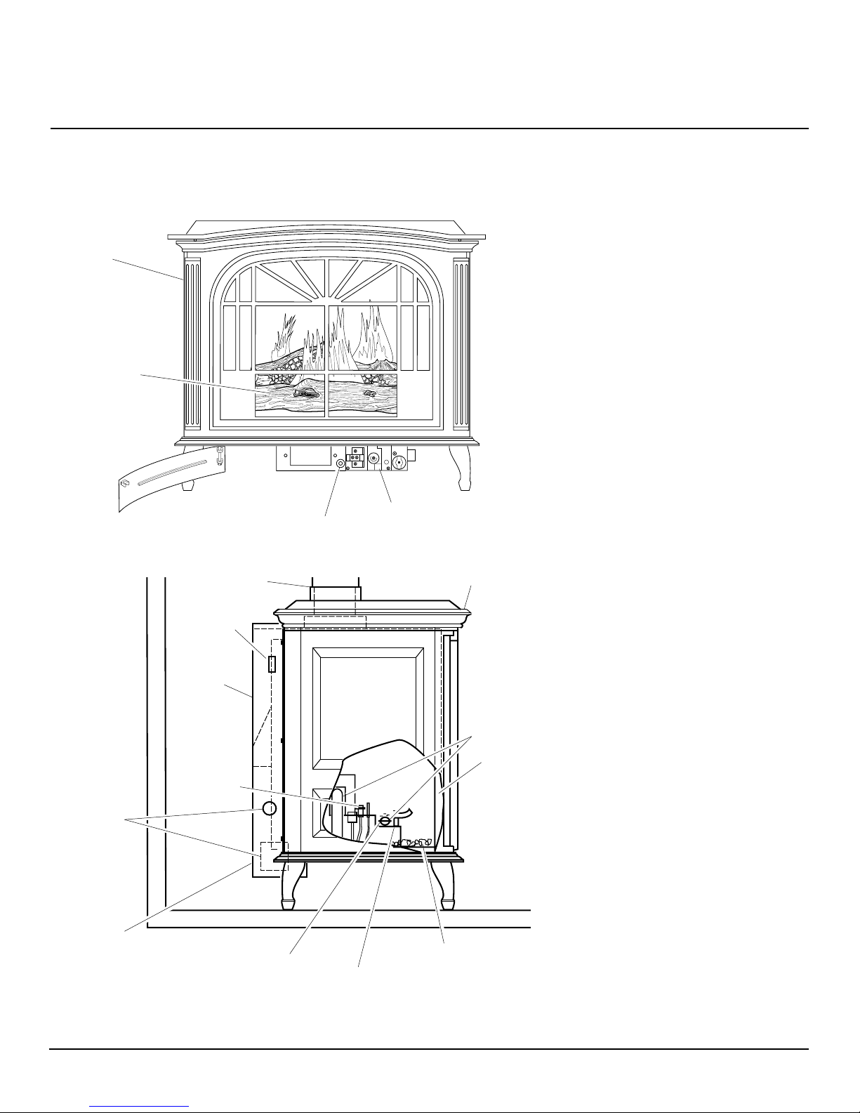
CAST IRON STOVE AND BURNER SYSTEM
107281
SUN VALLEY STOVE COMPANY
For more information, visit www.desatech.com
SAFETY
INFORMATION
1. This appliance is only for use with the
typeofgas indicatedon the ratingplate.
Thisappliance is notconvertible foruse
with other gases unless a certified kit
is used.
2. For propane/LP burner system, do not
place propane/LP supply tank(s) inside
any structure. Locate propane/LP sup-
ply tank(s) outdoors. To prevent perfor-
manceproblems, donot usepropane/LP
fuel tank of less than 100 lbs. capacity.
3. If you smell gas
• shut off gas supply
• do not try to light any appliance
• do not touch any electrical switch; do
not use any phone in your building
• immediately call your gas supplier
from a neighbor’s phone. Follow the
gas supplier’s instructions
• if you cannot reach you gas supplier,
call the fire department.
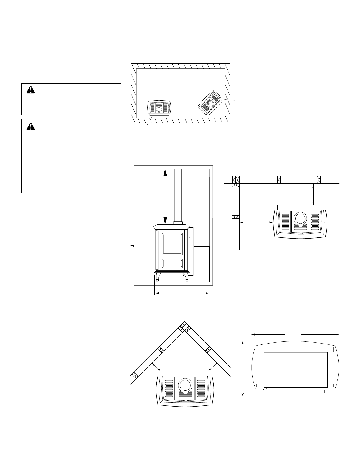
4. Never install the stove
• in a recreational vehicle
• wherecurtains,furniture, clothing,or
otherflammableobjects are lessthan
42" from the front, top, or sides of
the fireplace
• in high traffic areas
• in windy or drafty areas
5. This stove reaches high temperatures.
Keepchildren andadultsaway fromhot
surfacestoavoid burns orclothing igni-
tion. Stove will remain hot for a time
after shutdown. Allow surfaces to cool
before touching.
6. Carefully supervise young children
when they are in the room with stove.
7. Do not modify this burner or stove un-
der any circumstances. Any parts re-
moved for servicing must be replaced
priortooperating stoveorburner system.
8. Turn burner system off and let cool
before servicing, installing, or repair-
ing. Only a qualified service person
should install, service, or repair the
stove or burner system. Have burner
system inspected annually by a quali-
fied service person.
9. You must keep control compartments,
burners, and circulating air passages
clean. More frequent cleaning may be
needed due to excessive lint and dust
from carpeting, bedding material, pet
hair, etc. Turn off the gas valve and pi-
lot light before cleaning stove.
IMPORTANT: Read this owner’s
manual carefully and completely
before trying to assemble, oper-
ate,orservicethisstoveandburner
system.Improperuseofthisstove
and burner system can cause se-
rious injury or death from burns,
fire, explosions, electrical shock,
and carbon monoxide poisoning.
WARNING: Any change to
thisstoveorburnersystemorits
controls can be dangerous.
WARNINGS
DANGER: Carbon monoxide
poisoning may lead to death!
This stove with burner system is a vented
product. This stove with burner system will
notproduceanygasleakageintoyourhomeif
properlyinstalled.Thisstovemustbeproperly
installed by a qualified service person. The
glassdoormustbeproperlyseatedandsealed.
If this unit is not properly installed by a quali-
fied service person with glass door properly
seated and sealed, gas leakage can occur.
Carbon Monoxide Poisoning: Early signs
of carbon monoxide poisoning resemble the
flu, with headaches, dizziness, or nausea. If
youhavethesesigns,thestovemaynot have
been installed properly. Get fresh air at
once! Have stove inspected and serviced by
a qualified service person. Some people are
moreaffected bycarbonmonoxide thanoth-
ers. These include pregnant women, people
with heart or lung disease or anemia, those
under the influence of alcohol, and those at
high altitudes.
Propane/LP gas and natural gas are both
odorless.An odor-makingagentisaddedto
each of these gases. The odor helps you
detect a gas leak. However, the odor added
to these gases can fade. Gas may be present
even though no odor exists.
Make certain you read and understand all
warnings.Keepthismanualforreference.It
isyourguidetosafeandproperoperationof
this stove and burner system.
10. Have venting system inspected annu-
ally by a qualified service person. If
needed, have venting system cleaned
or repaired. See Cleaning and Mainte-
nance, page 22.
11. Keep the area around your stove clear
of combustible materials, gasoline, and
other flammable vapor and liquids. Do
not run burner system where these are
used or stored. Do not place items such
as clothing or decorations on or around
stove.
12. Do not use this stove to cook food or
burn paper or other objects.
13. Never place anything on top of stove.
14. Do not use any solid fuels (wood, coal,
paper, cardboard,etc.) inthis stove. Use
only the gas type indicated on burner
system nameplate.
15. This appliance,wheninstalled, must be
electrically grounded in accordance
with local codes or, in the absence of
local codes, with the National Electri-
cal Code, ANS/NFPA 70, or the Cana-
dian Electrical Code, CSA C22.1.
16. Do not obstruct the flow of combus-
tion and ventilation air in any way. Pro-
vide adequate clearances around air
openings into the combustion chamber
alongwithadequate accessibility clear-
ancefor servicing andproper operation.
17. Do not install stove directly on carpet-
ing, vinyl tile, or any combustible mate-
rial other than wood. The stove must set
on a metal or wood panel extending the
full width and depth of the stove.
18. Do not use stove or burner system if
any part has been exposed to or under
water. Immediately call a qualified ser-
vice person to arrange for replacement
of the unit.
19. Do not operate burner system if any
log is broken.
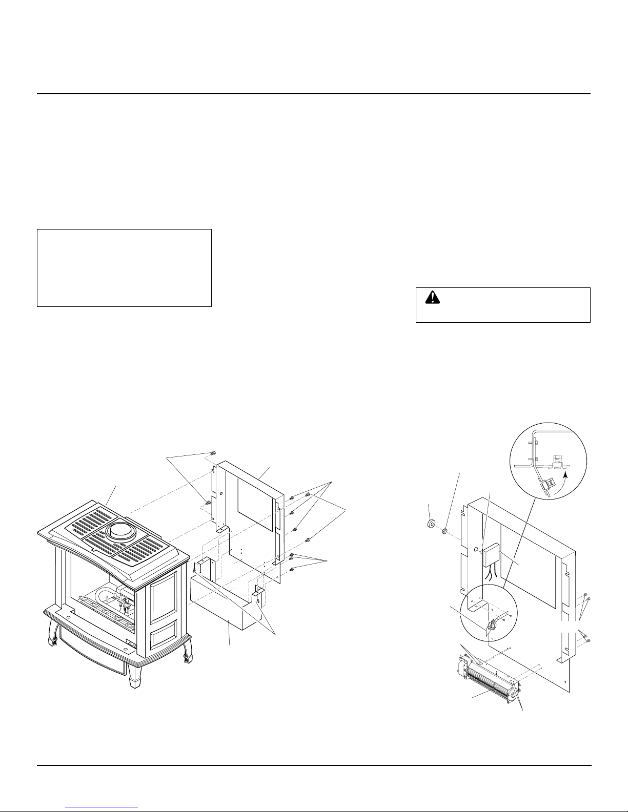
20. Do not use a blower insert, heat ex-
changer insert, or other accessory not
approved for use with this stove.
21. Do not operate burner system with
glass door removed, cracked, or bro-
ken.
22. This burner system must be properly
connected to a vent system. This burner
system is equipped with a vent safety
shutoff system.