Franco Belges MONTFORT 134 05 01 User manual

Description of the appliance
Installation instructions
Operating instructions
Spare parts
Warranty certificate
Document n° 1171-~ 20/02/2013
MONTFORT
Wood stove
EN 13240
Model : 134 05 01
Output : 5 kW Technical manual
to be saved
by the user
for future reference
FR EN NL IT
Parc d’activités de la Verte Rue
Allée des Prêles
59270 BAILLEUL
Tél. : 03 28 40 32 50

2Technical manual “1171”
“MONTFORT” - ref. 134 05 01
CONTENTS
Description of the unit ...................................p.3
Package ..................p.3
Optional equipment............p.3
Specifications ...............p.3
Description ................p.3
Operating principle ............p.3
Installation instructions...................................p.4
Warning to the user ...........p.4
Location of the unit ............p.4
Flue ....................p.4
Assembly of flue collar ..........p.5
Chimney connector............p.6
Pre-utilisation check ...........p.6
Door closing pressure ..........p.6
Maintenance of the Chimney ......p.6
Instructions for user.....................................p.7
Fuel ....................p.7
Instructions for use with wood ......p.8
Instructions for use with solid fuel....p.8
Cleaning..................p.9
Maintenance of the Chimney ......p.9
Maintenance of the stove ........p.9
Recommendations ............p.9
Firebricks .................p.9
Trouble Shooting ............p.10
Spare parts .........................................p.11
FRANCO BELGE congratulates you on your choice.
FRANCO BELGE, guarantees the quality of its appliances and is committed to meet its
customers’ needs.
FRANCO BELGE, which can boast a 80-year experience in the industry of heating devices, uses
state-of-the-art technologies
to design and manufacture its whole range of products.
This document contains instructions on how to install your appliance and make full use of its
functions, both for your comfort and safety.

This appliance is meant to burn wood or solid fuel safely
WARNING
Incorrectly installed, this appliance can be dangerous and possibly cause serious accidents.
We recommend that you engage the services of a professional engineer for its installation
and the regular maintenance requirements
1.Description of the unit
1.1. Package
•1 package : Stove
1.2. Optional equipment
•Set of 4 high legs. (black Y).
1.3. Specifications
Model . . . . . . . . . . . . . . . . . 134 05 01
Chimney draft required. . . . . . . Pa 12
Hearth dimensions
- Width . . . . . . . . . . . . . . . mm 330
- Depth . . . . . . . . . . . . . . . mm 205
- Height . . . . . . . . . . . . . . mm 240
Ash pan capacity......... liters 3
Weight . . . . . . . . . . . . . . . . kg 75
Heated volume . . . . . . . . . . . m3150
Wood
- Nominal Heat Output. . . . . . . kW 5
- Efficiency classification . . . . . . % 75
- Co (13% O2) . . . . . . . . . . . . % 0,49
- Smoke temperature . . . . . . . . °C 287
- Fuel rate . . . . . . . . . . . . . . . . kg/h 1,8
Fuel : ANTHRACITE (smokeless fuel)
- Nominal Heat Output. . . . . . . kW 3,3
- Efficiency classification . . . . . . % 61
- Co (13% O2) . . . . . . . . . . . . % 0,13
- Smoke temperature . . . . . . . . °C 304
- Fuel rate . . . . . . . . . . . . . . kg/h 0,6
The performances indicated opposite result from tests
carried out in accordance with standard EN13240 with
logs of Ø 12 of 30 cm and a depression of 12 Pa.
1.4. Description
Wood in conformity with EN 13240
•Detachable flue spigot for rear or top chimney
connection.
•Front loading door fitted with large refractory glass
panel.
•Adjustable air controls for controlling the burning rate.
•Spin wheel for lighting.
•Large ash-pan.
•De-scaling lever.
1.5. Operating
principle
The “MONTFORT”
is designed for
operation with the
door closed.
Heat is mainly
diffused by
radiation, through
the window and
body of the
appliance.
Combustion occurs
on the grate, with
draught entry
through the top of
the combustion
chamber.
Technical manual “1171” 3
“MONTFORT” - ref. 134 05 01 Description of the unit
Figure 1 - Dimensions in mm
Fuel : WOOD
Logs dimensions
- Lenght maxi. . . . . . . . . . . . cm 32
Number of logs . . . . . . . . . . . . . . 2
Interval ol charge . . . . . . . . . . . mn 60
Fuel load. . . . . . . . . . . . . . . . kg 0,6
Interval ol charge . . . . . . . . . . . mn 60

2. Installation instructions
2.1. Warning to the user
All the local and national
regulations, and in particular
those relating to national and
European standards, must be
observed when installing the
appliance.
An incorrectly installed
heating appliance can cause
serious accidents (chimney
fires, burning of plastic
insulation materials, in partition
walls, etc.).
The insulation of both the
appliance and the exhaust gas
pipe has to be reinforced and
done according to the Standards
and the Building Regulations for
safety reasons. The installation
must be carried out according to
the Standards and the Building Regulations.
Failure to respect the mounting instructions leads to
engage the responsibility of the one doing the
installation.
The manufacturer’s responsibility shall be limited to the
supply of the appliance.
2.2. Location of the unit
Ventilation :
For satisfactory appliance operation with a natural
draught, check that sufficient air for combustion is
available in the room.
in houses equipped with one VMC (controlled
mechanical ventilation), this one aspire and renew the
ambient air ; In this case, the residence is under slight
low pressure and a non-sealable external air intake
must be installed in addition to the chimney itself, at
least 50cm² in section.
Position of the unit :
For new installations, select a central position within the
house, to provide a good heat distribution around the
building.
The heat distribution towards the other rooms will be
made through the communicating doors.
These rooms must be in negative pressure or must
include ventilation gratings.
Floor and walls :
Make sure that the floor can support the weight of the
appliance, its surroundings and the hood. In the
contrary the floor needs to be reinforced with a concrete
screed to distribute this load.
Make sure they are not combustible or covered with
combustible material (as per the Building regulations).
Otherwise it must necessary to install a
non-combustible protection.
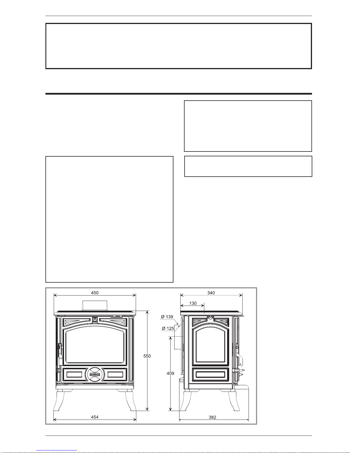
There must be a clearance of at least 150 mm at each
side of the appliance and at the back of the appliance
from a non-combustible wall.
This measurement may be reduced to a minimum gap
of 50 mm when the non-combustible wall is at least
200 mm thick.
This distance must be extended to a minimum
clearance of 425 mm from any combustible materials.
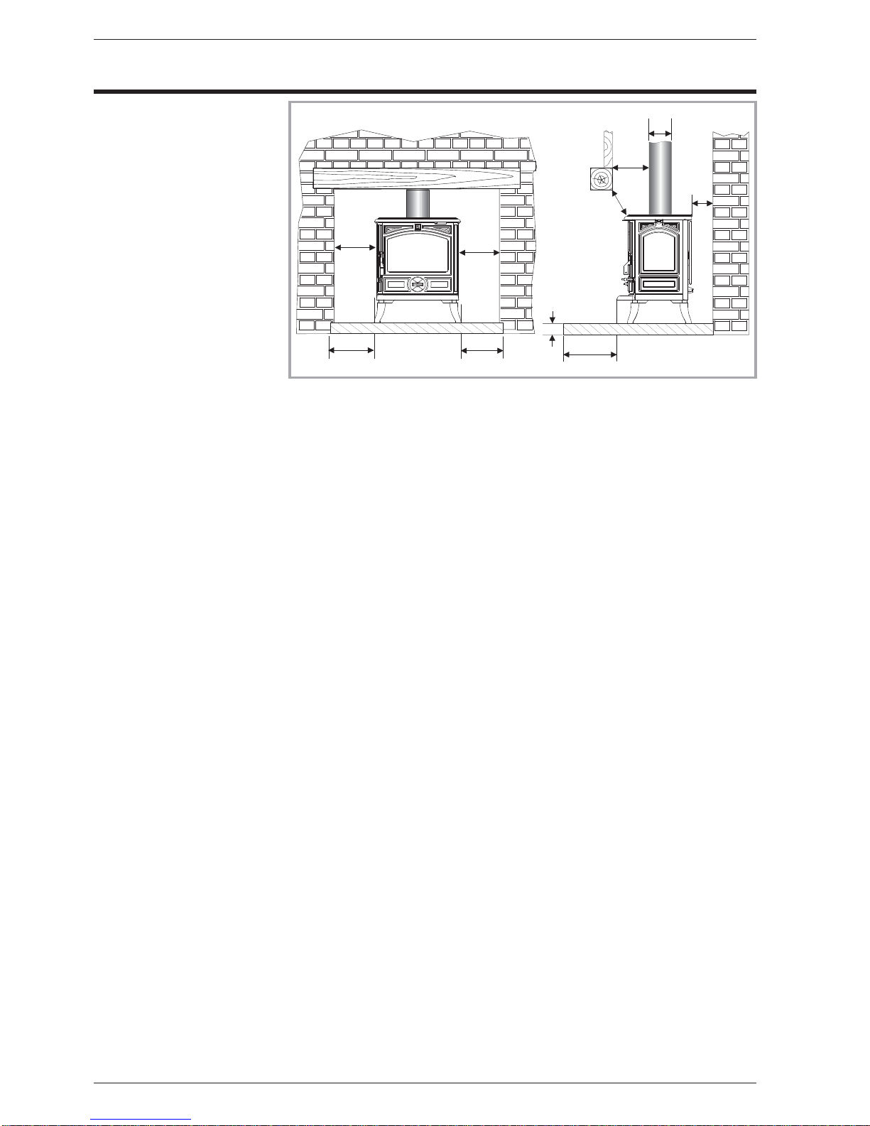
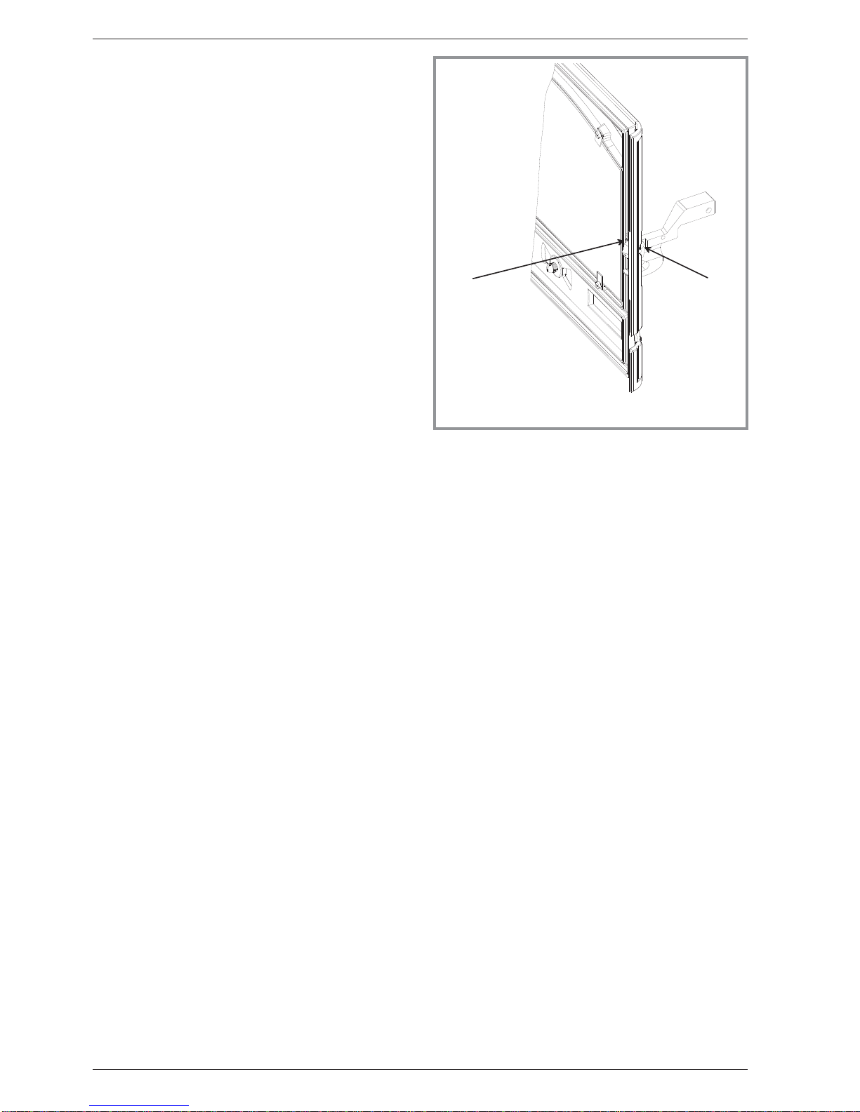
When using a single wall flue pipe, there must be a
clearance (A) of at least three times its diameter (B)
from any combustible materials.
If the appliance has to be located in an opening, this
distance must be extended to a minimum clearance (A)
of 375 mm from the pipe or the stove body to any
combustible materials.
Hearth :
The appliance must stand on a fireproof hearth.
It is possible to provide a hearth made of non
combusible board/sheet material or tiles at least 12 mm
thick (C).
Constructional hearths should be constructed of solid
non combustible material at least 125 mm thick
(including the thickness of any non combustible floor
under the hearth).
The hearth must protrude at least 225 mm in front of the
stove and 150 mm each side.
If the hearth is constructed on timber, there must be a
clearance of at least 250 mm from the timber to the top
surface of the hearth. See section J of the Building
regulations.
2.3. Flue
Existing flue :The chimney must comply with Current
Building Regulations. If in doubt, consult your Dealer or
local Building Inspector.
-The flue must be in good condition and must provide
sufficient draught.
-The flue must be suitable for the installation of solid
fuel burning appliances and comply with Current
Building Regulations.
-The flue must be clean. It should be swept to remove
soot and dislodge tar deposits.
-The flue must be well insulated. If the flue inner wall
surfaces are cold, a good thermal draw is impossible
causing condensation problems (tar formation etc) to
occur.
-The flue must not be shared with other appliances.
4Technical manual “1171”
“MONTFORT” - ref. 134 05 01 Installation instructions
1 5 0
1 5 0 1 5 0 3 0 0
1 5 0
B
A
A
C
1 5 0
Figure 2 - Clearances

-The chimney must be at least 4.5 m (15 ft high).
-In case of a flat roof or when the roof gradient is lower
than 15°, the stack must be 1,2 m (4 feet) high at least.
-If the chimney has any down draught tendency, due to
its position in relation to nearby obstacles, then an
anti-down draught cowl must be installed on the
chimney or the chimney height must be increased.
-If the decompression in the chimney is excessive, a
draught stabiliser must be installed.
Chimney to be built / New flue : The chimney must
comply with Current Building Regulations. If in doubt,
consult your Dealer or local Building Inspector.
-The appliance must not support the weight of the flue.
-It must be distant from any combustible material
(walls, cross members)
-It must permit an easy sweeping.
2.4. Assembly of flue collar
The stove is supplied with a connection flue spigot with
an inner diameter of 125 mm and an outer diameter of
139 mm.
2.4.1. Smoke exit on the top (figure 4)
•Remove the internal baffle (fig. 3).
•Fit the sealing rope in the groove on the top and fix the
flue collar with the bolts and washers supplied.
•Replace the internal baffle.
2.4.2. Smoke exit at rear (figure 5)
•Remove the internal baffle (fig. 3) and the rear heat
shield.
•Remove the clamp and the blanking plate fixed to the
back wall and replace it on the top.
•Fix the flue collar at rear with the bolts and washers
supplied, ensuring there is a good seal.
•Replace the internal baffle.
•Remove the cut-out in the rear heat shield and re-fit.
Technical manual “1171” 5
“MONTFORT” - ref. 134 05 01 Installation instructions
Figure 3 - Removing the flue baffle
Figure 4 - Smoke exit on the top
Figure 5 - Smoke exit at rear

2.5. Chimney connector
-The connection to flue must be carried out
according to local building regulations.
-The appliance must be installed as close as possible
to the chimney.
-The connector pipe must be approved for installation
with combustion products (either 24 ga. Black painted
or blued steel or 316 grade 20 ga. Stainless steel or 1
mm vitreous enamelled steel).
-Pipe diameter must not be less than the appliance
spigot diameter. If there is no other solution, the
reduction can not be more than one diameter lower
than the flue spigot and be situated as distant as
possible from the flue connection of the appliance.
-The connection can be either vertical or horizontal. For
horizontal connections, avoid right angle bends.
-The join between the connection pipe and the
stovepipe, and the flue, must be leak tight.
-For the premises equipped with a mechanical
controlled ventilation, the airtightness has to prevent
the exhauster drawing out the smokes from the
exhaust gas pipe.
-The connection pipe and any draught stabiliser must
have access for cleaning.
-The spigot should be connected to a minimum of 125
mm flue system and in that case the appliance is
capable of burning untreated wood and recommended
solid fuels.
2.6. Pre-utilisation check
Check the condition of the filler seals, that the door
closes correctly, that the window is not damaged, that
the smoke passages are not obstructed by pieces of
packaging or removable parts. All removable parts, fuel
retainer, oscillating grate, baffle, must be correctly
installed.
Note : if it acts of a ceramics braid, it is consumable and
thus brought to be changed by the user.
2.7. Door closing pressure
Figure 6
The closing latch rotates around a pressure screw
positioned cam.
-Loosen pressure screw 1,
-Turn cam to desired position. 2,
-Tighten pressure screw 1.
2.8. Maintenance of the Chimney
Very important : In order to avoid any incident
(chimney fire, etc...), maintenance tasks must be
carried out regularly. If the appliance is regularly used,
the chimney should be swept several times per year,
together with the stovepipe connection section.
If the chimney catches fire, you must cut off the flue
draught, close the doors and windows, hatches and
keys, remove the embers from the stoveDQGFDOO
the Fire%ULJDGHZLWKRXWGHOD\
DO NOT OPEN THE DOOR OF THE APPLIANCE
(OR AIR INLET) UNDER ANY CIRCUMSTANCES
Chimney condition should be checked at least once per
year by a professional engineer.
6Technical manual “1171”
“MONTFORT” - ref. 134 05 01 Installation instructions
Figure 6 - Adjusting of the door closing pressure
1Pressure screw 2Cam

3. Instructions for user
The manufacturer will not be responsible for damages
on parts of the appliance due to the use of prohibited
fuel or due to an alteration of the appliance or its
installation.
Only use replacement parts supplied by the
manufacturer.
All the local and national regulations, and in
particular those relating to national and European
standards, must be observed when using the
appliance.
Don’t run the stove in mild weather with coal : Under
certain circumstances (e.g. fog and repeated thaw)
the chimney will not draw sufficiently well and thus
be at the origin of asphyxia.
Awaiting better weather circumstances, don’t use
any coal but only wood.
At the first lighting, the fire must be progressively
increased to allow the various parts to expand normally
and to dry up.
Note : When the fire is lit for the first time, the stove may
give off fumes from the new paint. This is normal but
ensure the room is well ventilated during the first few
hours of operation.
Warning : properly installed and operated this
appliance will not emit fumes into the dwelling.
Occasional fumes from de-ashing and re-fuelling may
occur. Persistent fume emission is dangerous and must
not be tolerated. If fume emission does persist :
Open doors and windows to ventilate room.
Let the fire out and dispose of fuel from the appliance.
Check for flue or chimney blockage, and clean if
required.
Do not attempt to relight the fire until the cause of the
fume emission has been identified and corrected. If
necessary seek expert advice.
Note : It is recommended to use a fireguard in the
presence of children, and also in the presence of old
and/or infirm people.
3.1. Fuel
This appliance is not an incinerator.
Recommended fuel : Wood
Use hard wood logs, which have been cut for at least
two years and stored, under shelter.
Hardwood has a higher calorific value per cu metre
(oak, ash, maple, birch, elm, beech, etc.).
Large logs must be split and cut to a usable length,
before being stored in a sheltered and ventilated place.
Recommended fuel : Coal
Smokeless fuels, including coolite nuts, phurnacite,
ancit and extracite.
Not recommended as fuel :
“green wood”. Green or damp wood reduces stove
efficiency and soils the glass, the internal walls and the
flue (soot, tar, etc.).
“used timbers”. Burning treated wood (railway
sleepers, telegraph poles, offcuts of plywood or chip
board, pallets, etc.) quickly clogs the flue ways (soot,
tar, etc.), pollutes the environment (pollution and smell,
etc.) and cause the fire to burn too quickly and
overheat.
“Green wood” and “recovered wood” can eventually
cause a chimney fire.
Prohibited fuel : any form of housecoal (bituminous
coal) or petroleum based coke.
Technical manual “1171” 7
“MONTFORT” - ref. 134 05 01 Instructions for user
Figure 7 - Operating devices
A:Door lock
B:draught control (secondary air inlet)
B1= flap opened B2 = flap closed
C:Spin wheel for lighting (primary air inlet)
C1 = wheel opened C2 = wheel closed
D:Grate shaker control
E:Prehension tool

3.2. Instructions for use with wood
3.2.1. Lighting (figure 7)
•Slide the secondary air inlet (# B1) to the right. Open
the primary air inlet (# C1).
•Lay firelighters or rolled up newspapers on the grate
with a reasonable quantity, if necessary, of dry kindling
wood. Place 2 or 3 small logs on top.
•Light the newspaper or firelighters using a long taper
and close the door.
•When the stove body is very hot, close the lower spin
wheel.
•The burning rate can now be lowered by moving the
top air control to the left.
The airwash system works with the top airslide. When
the top airslide is full open the system works at its
strongest efficiency.
The more closed down the airslide is, the less effective
the airwash will be ( when shut down completely, the
airwash system can not function )
3.2.2. Re-fuelling (figure 7)
•Open the glass door and add logs.
•Leave the lower spin wheel open for a few minutes to
allow the initial volatiles in the wood to burn.
•Close the lower spin wheel.
3.3. Instructions for use with solid fuel
3.3.1. lighting (figure 7)
•Slide the secondary air inlet (# B1) to the right. Open
the primary air inlet (# C1).
•Lay firelighters or rolled up newspapers on the grate
with a reasonable quantity, if necessary, of dry kindling
wood. Place a small quantity of solid fuel on top.
•Light the newspaper or firelighters using a long taper
and close the door.
•When the fire is burning fiercely, add further fuel.
•When the stove body is hot, close the top air control by
sliding to the left.
•The burning rate can now be adjusted by rotating the
lower spin wheel.
The airwash system works with the top airslide. When
the top airslide is full open the system works at its
strongest efficiency.
The more closed down the airslide is, the less effective
the airwash will be ( when shut down completely, the
airwash system can not function )
3.3.2. Re-fuelling
-Open the lower spin wheel.
-Open the glass door and add fuel.
-Leave the lower spin wheel open for a few minutes to
allow the initial volatiles in the fuel to burn.
-Adjust the lower spin wheel to the desired position.
8 Technical manual “1171”
“MONTFORT” - ref. 134 05 01 Instructions for user
Figure 8 - Removing the fuel retainer
Figure 9 - Mounting the oscillating grate and the ash
tray
• The nominal output is obtained with an opening of the
primary air inlet closed and secondary air inlet of 50 %
open.

3.4. Cleaning
It is essential to keep the grate free from a heavy build
up of ashes. The Belfort is equipped with a grate
riddling device which is used to “shake” ashes off the
grate into the ash pan.
Whenever the stove is burning without life when the
lower spin wheel is open, use the riddling lever to clear
the grate of surplus ashes.
REMEMBER TO BURN SOLID FUEL CORRECTLY,
AlR SHOULD BE ALLOWED TO FLOW FROM THE
ASH PIT AREA THROUGH THE GRATE AND
THROUGH THE FUEL. IF THE GRATE OR ASH PAN
ARE CONGESTED, THE PERFOMANCE WILL BE
EFFECTED.
If burning solid fuel, always empty the ash pan at least
once a day or whenever it is full of ashes. Never allow
the ashpan to overfill allowing ash to be in contact with
the underside of the grate. If this condition is allowed,
the grate will wear out pre-maturely.
3.5. Maintenance of the Chimney
Very important : In order to avoid any incident
(chimney fire, etc...), maintenance tasks must be
carried out regularly. If the appliance is regularly used,
the chimney should be swept several times per year,
together with the stovepipe connection section.
If the chimney catches fire, you must cut off the flue
draught, close the doors and windows, hatches and
keys, remove the embers from the stove, stop up
the connection hole with wet cloths and call the Fire
Brigade.
DO NOT OPEN THE DOOR OF THE APPLIANCE
(OR AIR INLET) UNDER ANY CIRCUMSTANCES
Chimney condition should be checked at least once per
year by a professional engineer.
3.6. Maintenance of the stove
•The appliance must be cleaned regularly, together with
the connecting pipe and the flue pipe.
•Remove all deposits from the combustion chamber
and clean the grate area.
•Cleaning of the glass door can be done with a soft cloth
dampened with water and vinegar or potassium ; this
must be done when the appliance is cold ; then rinse
with clear water. Do not use abrasive cleaners.
•The “vitroceramic” glass will resists to temperatures of
up to 750 C. Should the glass break due to misuse, it
must be replaced by the manufacturers own product.
•All the casing parts can be cleaned using a soft cloth
either dry, or slightly damp. In case of condensation or
water splashes clean the parts before they dry out.
•Check that the ash removal grill is installed and
operating correctly (fig. 9).
•Check that there are no obstructions before relighting
after a long period of disuse.
•The appliance must not be used with a flue serving
several appliances.
•To maintain the grates ventilation free of any
obstruction,
Warning ! The appearance of cracks when burning the
enamelled units is quite usual and tends to disappear
when the appliance is cooling down. It should not be
considered as a defect but rather as a patina of the
enamel which does not affect its quality nor its service
ability.
3.7. Recommendations
This room heater is an appliance producing heat and
may cause severe burns if touched.
FThe stove may still be hot even when fire has
burnt out.
KEEP CHILDREN AWAY.
3.8. Firebricks
When replacing firebricks, the fire must be
progressively increased to allow the firebricks to
expand normally and to dry up.
Technical manual “1171” 9
“MONTFORT” - ref. 134 05 01 Instructions for user

3.9. Trouble Shooting
Problem Probable causes -Action
Fire difficult to start. Fire goes
out.
Wood green… or too damp -Use hard wood logs, which have been cut for at least
two years and stored, under a ventilated shelter.
Logs are too big -To light the fire, use small, very dry twigs. To maintain
the fire, use split logs.
Poor quality wood -Use hardwood that have a higher calorific value per cu
metre (Yoke-elm, oak, ash, maple, birch, elm, beech,
etc.)
Not enough primary air -Open air control.
Insufficient draught þ-Check that the flue is not obstructed, sweep it if
necessary
-Seek advice from a chimney specialist.
Fire burns too quickly Too much draught -Partially close the air control.
Excessive draught þ-Install a draught stabiliser to the connector pipe.
Poor quality wood -Do not continuously burn small wood, sticks, bundles,
carpentry offcuts (plywood, pallets), etc.
Smokes when lighting up Flue duct is cold -Burn paper and kindling wood to increase heat.
Room is in decompression
(negative pressure)
-In houses equipped with mechanical ventilation, partly
open a window until the fire is well established.
Smokes while burning. Insufficient draught þ-Vérifier la conformité du conduit de fumée et son
isolation.
-Check that the flue is not obstructed, sweep it if
necessary
Down draught þ-Install an anti-down draught cowl.
Room is in decompression
(negative pressure).
þ-In houses equipped with mechanical ventilation, partly
open a window until the fire is well established.
Low heat output. Poor quality wood. -Use hardwood that have a higher calorific value per cu
metre (Yoke-elm, oak, ash, maple, birch, elm, beech,
etc.)
Poor mixing of the convection air -Check the air flow system (air inlet, piping, air outlet).
-Check that the next rooms are equiped with ventilation
grids to help out the hot air circulation.
10 Technical manual “1171”
“MONTFORT” - ref. 134 05 01 Instructions for user
þ: This sign means that you should
asked for a qualified engineer to do the
work.

4. Spare parts
When ordering spare parts, specify the stove type and serial number, including the colour index (on the
guarantee or identification plate), the name of the part and the part number.
Example : Wood stove “MONTFORT”, ref. 134 05 01, colour C, Top plate 352168 MK.
Technical manual “1171” 11
“MONTFORT” - ref. 134 05 01 Spare parts
1 100917 .....Campin........12x20 M7 ......A...B...C...D...E...F...G...01
2 100939 .....Axle ......................A...B...C...D...E...F...G...02
3 105123 .....Knob......................A...B...C...D...E...F...G...01
4 105273 .....Firebrick ....................A...B...C...D...E...F...G...01
5 105274 .....Firebrick ....................A...B...C...D...E...F...G...02
6 134253 .....Bushing ....................A...B...C...D...E...F...G...01
7 142881 .....Gasket.....................A...B...C...D...E...F...G...04
8 166003 .....Spring ..........11x15 .......A...B...C...D...E...F...G...01
9 181632 .....Gasket...........Ø6 .......A...B...C...D...E...F...G .1,05 m
10 181633 .....Gasket ..........d,10.......A...B...C...D...E...F...G .2,82 m
11 181634 .....Gasket ..........d,15.......A...B...C...D...E...F...G .1,36 m
12 188830 .....Ceramic glass.................A...B...C...D...E...F...G...01
13 189103 .....Screw ..........27x8x6 ......A...B...C...D...E...F...G...01
14 189104 .....Screw ...........6x22 .......A...B...C...D...E...F...G...02
15 207316 00 . . . Back panel ..................A...B...C...D...E...F...G...01
16 222568 00 . . . Flue baffle...................A...B...C...D...E...F...G...01
17 237421 00 . . . Reducing plate ................A...B...C...D...E...F...G...01
18 259015 00 . . . Fixing plate ..................A...B...C...D...E...F...G...04
19 262612 00 . . . Heat shield ..................A...B...C...D...E...F...G...01
20 270412 00 . . . Air control flap ................A...B...C...D...E...F...G...01
21 300118 MK ...Leg...................................D ...............04
21 300118 MP ...Leg .......................................E...........04
21 300118 RH ...Leg............................................F.......04
21 300118 RP ...Leg................................................G...04
21 300118 EF ...Leg ......................A............................04
21 300118 77 ...Leg...............................C....................04
21 300118 79 ...Leg...........................B........................04
22 300493 00 . . . Base......................A...B...C...D...E...F...G...01
23 301526 MK . . . Door lock ................................D...............01
23 301526 MP . . . Door lock ....................................E...........01
23 301526 RH . . . Door lock ........................................F.......01
23 301526 RP . . . Door lock.............................................G...01
23 301526 EF . . . Door lock ...................A............................01
23 301526 77 . . . Door lock ............................C....................01
23 301526 79 . . . Door lock .......................B........................01
24 301742 MK . . . Air damper ...............................D...............01
24 301742 MP . . . Air damper ...................................E...........01
24 301742 RH . . . Air damper........................................F.......01
24 301742 RP . . . Air damper ............................................G...01
24 301742 EF . . . Air damper ..................A............................01
24 301742 77 . . . Air damper ...........................C....................01
24 301742 79 . . . Air damper.......................B........................01
25 301901 00 . . . Oscillating grate................A...B...C...D...E...F...G...01
26 303718 MK . . . Blanking plate .............................D ...............01
26 303718 MP . . . Blanking plate..................................E...........01
26 303718 RH . . . Blanking plate ......................................F.......01
26 303718 RP . . . Blanking plate ..........................................G...01
26 303718 EF . . . Blanking plate .................A............................01
26 303718 77 . . . Blanking plate .........................C....................01
26 303718 79 . . . Blanking plate .....................B........................01
N° Code .....Designation .......Type .......A...B...C...D...E...F...G..Qty
A= 1340501 Y;B= 1340501 J;C= 1340501 L;D= 1340501 C
E= 1340501 I;F= 1340501 P;G= 1340501 E

12 Technical manual “1171”
“MONTFORT” - ref. 134 05 01 Spare parts
Figure 10 - Stove - exploded view
3
45
45

Technical manual “1171” 13
“MONTFORT” - ref. 134 05 01 Spare parts
27 303860 MK . . . Flue collar . . . . . . . . . . . . . . . . . . . . . . . . . . . . . . . D . . . . . . . . . . . . . . . 01
27 303860 MP . . . Flue collar. . . . . . . . . . . . . . . . . . . . . . . . . . . . . . . . . . . . E . . . . . . . . . . . 01
27 303860 RH . . . Flue collar . . . . . . . . . . . . . . . . . . . . . . . . . . . . . . . . . . . . . . . . F . . . . . . . 01
27 303860 RP . . . Flue collar . . . . . . . . . . . . . . . . . . . . . . . . . . . . . . . . . . . . . . . . . . . . G. . . 01
27 303860 EF . . . Flue collar . . . . . . . . . . . . . . . . . . . A . . . . . . . . . . . . . . . . . . . . . . . . . . . . 01
27 303860 77 . . . Flue collar . . . . . . . . . . . . . . . . . . . . . . . . . . . C. . . . . . . . . . . . . . . . . . . . 01
27 303860 79 . . . Flue collar . . . . . . . . . . . . . . . . . . . . . . . B . . . . . . . . . . . . . . . . . . . . . . . . 01
28 306286 EF . . . Back wall . . . . . . . . . . . . . . . . . . . A . . . B . . . C . . . D . . . E . . . F . . . G. . . 01
29 307439 EF . . . Fuel retainer . . . . . . . . . . . . . . . . . A . . . B . . . C . . . D . . . E . . . F . . . G. . . 01
30 310735 MK . . . R. side panel . . . . . . . . . . . . . . . . . . . . . . . . . . . . . . D . . . . . . . . . . . . . . . 01
30 310735 MP . . . R. side panel . . . . . . . . . . . . . . . . . . . . . . . . . . . . . . . . . . E . . . . . . . . . . . 01
30 310735 RH . . . R. side panel . . . . . . . . . . . . . . . . . . . . . . . . . . . . . . . . . . . . . . F . . . . . . . 01
30 310735 RP . . . R. side panel. . . . . . . . . . . . . . . . . . . . . . . . . . . . . . . . . . . . . . . . . . . G. . . 01
30 310735 EF . . . R. side panel . . . . . . . . . . . . . . . . . A . . . . . . . . . . . . . . . . . . . . . . . . . . . . 01
30 310735 77 . . . R. side panel. . . . . . . . . . . . . . . . . . . . . . . . . . C. . . . . . . . . . . . . . . . . . . . 01
30 310735 79 . . . R. side panel . . . . . . . . . . . . . . . . . . . . . B . . . . . . . . . . . . . . . . . . . . . . . . 01
31 310831 MK . . . L. side panel . . . . . . . . . . . . . . . . . . . . . . . . . . . . . . D . . . . . ..........01
31 310831 MP . . . L. side panel . . . . . . . . . . . . . . . . . . . . . . . . . . . . . . . . . . E . . . . . . . . . . . 01
31 310831 RH . . . L. side panel. . . . . . . . . . . . . . . . . . . . . . . . . . . . . . . . . . . . . . . F . . . . . . . 01
31 310831 RP . . . L. side panel . . . . . . . . . . . . . . . . . . . . . . . . . . . . . . . . . . . . . . . . . . . G. . . 01
31 310831 EF . . . L. side panel . . . . . . . . . . . . . . . . . A . . . . . . . . . . . . . . . . . . . . . . . . . . . . 01
31 310831 77 . . . L. side panel . . . . . . . . . . . . . . . . . . . . . . . . . . C. . . . . . . . . . . . . . . . . . . . 01
31 310831 79 . . . L. side panel. . . . . . . . . . . . . . . . . . . . . . B . . . . . . . . . . . . . . . . . . . . . . . . 01
32 315611 EF . . . Air duct . . . . . . . . . . . . . . . . . . . . A . . . B . . . C . . . D . . . E . . . F . . . G. . . 01
33 319739 00 . . . Grate support . . . . . . . . . . . . . . . . . A . . . B . . . C . . . D . . . E . . . F . . . G. . . 01
34 324503 00 . . . Sealing plate . . . . . . . . . . . . . . . . . A . . . B . . . C . . . D . . . E . . . F . . . G. . . 01
35 325304 EF . . . Reducing plate . . . . . . . . . . . . . . . . A . . . B . . . C . . . D . . . E . . . F . . . G. . . 02
36 327906 MK . . . Ash pan guide . . . . . . . . . . . . . . . . . . . . . . . . . . . . . D . . . . . . . . . . . . . . . 01
36 327906 MP . . . Ash pan guide . . . . . . . . . . . . . . . . . . . . . . . . . . . . . . . . . E . . . . . . . . . . . 01
36 327906 RH . . . Ash pan guide . . . . . . . . . . . . . . . . . . . . . . . . . . . . . . . . . . . . . . F . . . . . . . 01
36 327906 RP . . . Ash pan guide . . . . . . . . . . . . . . . . . . . . . . . . . . . . . . . . . . . . . . . . . . G. . . 01
36 327906 EF . . . Ash pan guide. . . . . . . . . . . . . . . . . A . . . . . . . . . . . . . . . . . . . . . . . . . . . . 01
36 327906 77 . . . Ash pan guide . . . . . . . . . . . . . . . . . . . . . . . . . C. . . . . . . . . . . . . . . . . . . . 01
36 327906 79 . . . Ash pan guide . . . . . . . . . . . . . . . . . . . . . B . . . . . . . . . . . . . . . . . . . . . . . . 01
37 331118 MK . . . Main door. . . . . . . . . . . . . . . . . . . . . . . . . . . . . . . . D . . . . . . . . . . . . . . . 01
37 331118 MP . . . Main door . . . . . . . . . . . . . . . . . . . . . . . . . . . . . . . . . . . . E . . . . . . . . . . . 01
37 331118 RH . . . Main door . . . . . . . . . . . . . . . . . . . . . . . . . . . . . . . . . . . . . . . . F . . . . . . . 01
37 331118 RP . . . Main door . . . . . . . . . . . . . . . . . . . . . . . . . . . . . . . . . . . . . . . . . . . . G. . . 01
37 331118 EF . . . Main door . . . . . . . . . . . . . . . . . . . A . . . . . . . . . . . . . . . . . . . . . . . . . . . . 01
37 331118 77 . . . Main door . . . . . . . . . . . . . . . . . . . . . . . . . . . C. . . . . . . . . . . . . . . . . . . . 01
37 331118 79 . . . Main door . . . . . . . . . . . . . . . . . . . . . . . B . . . . . . . . . . . . . . . . . . . . . . . . 01
38 332001 EF . . . Air duct . . . . . . . . . . . . . . . . . . . . A . . . B . . . C . . . D . . . E . . . F . . . G. . . 01
39 352168 MK . . . Top plate . . . . . . . . . . . . . . . . . . . . . . . . . . . . . . . . D . . . . . . . . . . . . . . . 01
39 352168 MP . . . Top plate . . . . . . . . . . . . . . . . . . . . . . . . . . . . . . . . . . . . E . . . . . . . . . . . 01
39 352168 RH . . . Top plate . . . . . . . . . . . . . . . . . . . . . . . . . . . . . . . . . . . . . . . . F . . . . . . . 01
39 352168 RP . . . Top plate. . . . . . . . . . . . . . . . . . . . . . . . . . . . . . . . . . . . . . . . . . . . . G. . . 01
39 352168 EF . . . Top plate . . . . . . . . . . . . . . . . . . . A . . . . . . . . . . . . . . . . . . . . . . . . . . . . 01
39 352168 77 . . . Top plate . . . . . . . . . . . . . . . . . . . . . . . . . . . . C. . . . . . . . . . . . . . . . . . . . 01
39 352168 79 . . . Top plate. . . . . . . . . . . . . . . . . . . . . . . . B . . . . . . . . . . . . . . . . . . . . . . . . 01
40 406816 00 . . . Clamp . . . . . . . . . . . . . . . . . . . . . A . . . B . . . C . . . D . . . E . . . F . . . G. . . 01
41 458404 00 . . . Rod . . . . . . . . . . . . . . . . . . . . . . A . . . B . . . C . . . D . . . E . . . F . . . G. . . 01
42 624046 00 . . . Ash pan . . . . . . . . . . . . . . . . . . . . A . . . B . . . C . . . D . . . E . . . F . . . G. . . 01
43 808001 ED . . . Hand tool . . . . . . . . . . . . . . . . . . . A . . . B . . . C . . . D . . . E . . . F . . . G. . . 01
44 988901 . . . . . Complete door . . . . . . . . . . . . . . . . . . . . . . . . . . . . . D . . . . . . . . . . . . . . . 01
44 988902 . . . . . Complete door . . . . . . . . . . . . . . . . . . . . . . . . . . . . . . . . . E . . . . . . . . . . . 01
44 988898 . . . . . Complete door . . . . . . . . . . . . . . . . A . . . . . . . . . . . . . . . . . . . . . . . . . . . . 01
44 988900 . . . . . Complete door . . . . . . . . . . . . . . . . . . . . . . . . . C. . . . . . . . . . . . . . . . . . . . 01
44 988899 . . . . . Complete door. . . . . . . . . . . . . . . . . . . . . B . . . . . . . . . . . . . . . . . . . . . . . . 01
44 988903 . . . . . Complete door. . . . . . . . . . . . . . . . . . . . . . . . . . . . . . . . . . . . . . F . . . . . . . 01
44 988856 . . . . . Complete door. . . . . . . . . . . . . . . . . . . . . . . . . . . . . . . . . . . . . . . . . . G. . . 01
N° Code . . . . . Designation . . . . . . . Type . . . . . . . A . . . B . . . C . . . D . . . E . . . F . . . G . . Qty
45 105642 . . . . . Firebrick . . . . . . . . . . . . . . . . . . . .A . . . B . . . C . . . D . . . E . . . F . . . G. . . 01

Guarantee certificate
Legal guarantee
The specifications, dimensions and information shown
on our documents are provided for information purposes
only and under no circumstances are binding upon the
vendor.
With the aim of constantly improving our equipment, all
modifications considered as necessary by our
departments may be made without notice.
The provisions of the present guarantee certificate are
not excluding or limiting the owner of the equipment’s
rights, concerning the legal guarantee regarding faults or
hidden vices which applies in all circumstances, in the
conditions detailed in articles 1641and following of the
civil code, and in the country in which the equipment was
purchased.
Contractual guarantee
Our equipment is guaranteed against faults and hidden
vices subject to the following conditions:
1) Installation and adjustment of the device by a professional
installer.
2) Observance of the instructions provided in our technical
3) The installation, use and maintenance of the device carried
out in conformity with the applicable standards and
legislation,and with theindications providedin the technical
This guarantee covers the replacement, in our factory, of
parts recognised as being defective from the outset by
our “Guarantee Inspection” Department. Carriage and
labour is at the user’s cost. Moreover, if the repair or
replacement of parts covered by the guarantee is found
to be too costly vis-à-vis the price of the appliance, the
decision to replace or repair the appliance will be taken
by the vendor.
Our guarantee is for 2 (two) years for all appliances, with
the exception of closed combustion fireplace and inserts
for which our guarantee is 5 (five) years excluding the
following:
2) Parts subject to wear or in contact with high temperatures
namely: soles and burner grills, bottom plates baffles, ash
pans, paintwork and surface treatments for decorative
parts. Also excluded from this guarantee are seals and
windows.
3) Any damage which may result from the use of the appliance
4) Damage occurring to parts caused by elements outside the
appliance (down draught, storm damage, damp, abnormal
5) Damage to electrical parts caused by plugging in and using
the appliance on a mains system, the voltage of which
(measured at the entrance to the appliance) is 10% above
Exclusion of liability
In the case of a product manufactured at the client’s
request, under no circumstances may we, as a
subcontractor, be considered liable vis-a-vis the client or
third parties for defects arising from the installation or a
design fault with the item in question.
N
Telephone : ________________________ _
N
Date of installation : __ ___ / ___ ___ / ___ ___ ___ ___
Model of the appliance : 134 05 01
Color : Y J L C I P E
Serial number : ___ ___ ___ ___ ___ ___
In case of claims, send a copy of this to :
BOUTIQUES DU FEU - FRANCO BELGE
Parc d’activités de la Verte Rue - Allée des Prêles - 59270 BAILLEUL - FRANCE
Table of contents
Popular Wood Stove manuals by other brands

Broseley
Broseley Hotspur 9 Installation & operating instructions

Golden Eagle
Golden Eagle ECONOMY SERIES 5040 Owner’s Instruction and Operation Manual

Nordpeis
Nordpeis Salzburg XL installation manual

Firenzo
Firenzo KOMPACT user guide

hergom
hergom SHELBURNE Instruction book

United States Stove
United States Stove VOGELZANG TR007E manual

Vermont Castings
Vermont Castings Defiant 1945 Service manual

Harrie Leenders
Harrie Leenders Signa manual

Blaze King
Blaze King Royal Guardian RGT-3001 Owner's installation and operation manual

Pyroclassic Fires
Pyroclassic Fires IV Wood Burner operating instructions

Palazzetti
Palazzetti Ecofire Lilibet PRODUCT TECHNICAL DETAILS

Empire Comfort Systems
Empire Comfort Systems EMPIRE GATEWAY 2300 instructions