Sun2Solar 805401 User manual

™
INSTALLATION AND OPERATION MANUAL
Model Sku #s: 805401, 805430, 805431, 805404, 805405, 805406, 805407
Read all instructions before assembling or using the Sun2Solar™Heater Systems.
Retain this Manual for future use.
03/16
Distributed By:
Millstream Dist. LLC
1-800-253-4775

2
TABLE OF CONTENTS
Important Safety Information……………………………………………………….....2
How Sun2Solar™Heater Works…………………………………………………………3
Sizing Guide……………………………………………………………………………...3
List of Components……………………………………………..……………………..…3
Installation of Sun2Solar™Heater/Layout Options………………………..……….…4-6
Winterization………………………………………………………………….………….7
Repairs……………………………………………………………………………………7
Available Kits/Accessories……..…………………………………………………….…..7
Troubleshooting………………………………………………………………………….8
IMPORTANT SAFETY INFORMATION
CAUTION: Please read this Manual carefully and thoroughly. Improper installation or failure
to comply with the guidelines of this Manual may damage the product and will
void the warranty.
CAUTION: You are advised to consult with a professional when installing the Sun2Solar™Heater
on a roof, fence or rack system. When installing the collectors near the pool,
especially on an elevated rack system, ensure that the structure does not provide
access to the pool.
CAUTION: Installing the collectors over grass will cause damage to the lawn.
CAUTION: Do not walk on the collectors.
CAUTION: Turn off all pool equipment prior to installation.
CAUTION: Only use Sun2Solar™approved mounting equipment when installing collectors on
a roof, fence or rack system.
CAUTION: Wear and tear components (connector hoses, strapping, clamps, plastic fittings
and hardware) should be inspected regularly to ensure they are in working
condition. These components are not covered by the manufacturers’ limited warranty.

3
HOW SUN2SOLAR™HEATER WORKS
*The pool pump circulates the water through
the collectors
* The collectors absorb the heat from the sun
* Warm water is returned to the pool
Sun2Solar™heater collectors have a web
construction designed for maximum heat absorption
regardless of the position of the sun.
SIZING GUIDES
ABOVEGROUND POOLS
Round Oval 2 x 20 4 x 20
Up to 24’ Up to 15’ x 30’ 1 Box 1 Box
Up to 33’ Up to 21’x 41’ 2Boxes 1 Box
The 4x20 can be used but only a 2x20 is required*
LIST OF COMPONETS
2 X 20 - 805423
Item DESCRIPTION SKU# Qty
A 1.5” Stainless Steel Band Clamp - 214201 2
A 1.25” Stainless Steel Band Clamp- 214197 2
C PVC Elbow Connector - 214083 2
D Rubber End Cap- 108016 2
E Teflon Tape- 274119 1
F Backwash Fitting- 274062 2
4 x 20 – 805 424
Item DESCRIPTION Qty
A 1.5 Stainless Steel Band Clamp- 214201 4
A 1.25” Stainless Steel Band Clamp- 214197 2
B 3.75” Rubber Hose Connector- 108015 1
C PVC Elbow Connector - 214083 2
D Rubber End Cap- 108016 4
E Teflon Tape- 274119 1
F Backwash Fitting- 274062 2
INSTALLATION
READ THE ENTIRE MANUAL PRIOR TO THE INSTALLATION AND USE OF THE SUN2SOLAR™SYSTEM
TOOLS REQUIRED GUIDELINES FOR POSITIONING
Flathead screwdriver or 5/6” (8mm) nut driver * The collector(s) needs at least 6 hours of full sunlight daily.
* Plug for return fitting. * For ground installation, ensure the area is free of sharp objects
* For roof or rack mounting prior installation.
* Power Drill * A 1hp pump will handle installations up to 30ft from the pool
* 1/8” (3mm) drill bit equipment and a height of 1 story.
* #2 Phillips head drill bit. * The collector(s) can be installed on the ground, a roof, a rack or a fence.
*Silicone sealant (GEII or equivalent) Additional plumbing and hardware kits may be required(not included)
INGROUND POOLS- SM050004
Dimensions 2 x 20 4 x 20 Kits
Up to 15’ x 30’ 4 Boxes 2 Boxes 1 SM050004
Up to 16’ x 36’ 6 Boxes 3 Boxes 1 SM050004
Up to 20’ x 40’ 8 Boxes 4 Boxes 1 SM050004

4
2 x 20 INSTALLATION
This layout is for a single collector near the pool filter. Installing the collector on a rood, rack or fence may
require additional plumbing and hardware kits.
Rubber End Cap
1. Ensure there is adequate work space to unroll the 20’ collector.
2. Remove the collector from the box and the strap from around the collector.
3. Slowly uncoil the panel.
NOTE: Laying on the collector in the reverse direction of the coils
will help flatten the panel
4. Remove and discard the black protective caps covering the threaded portion of the headers.
5. Wrap the threaded ends of the headers with the provided Teflon tape to ensure a watertight seal.
6. Locate the header that does not have the white serial number label and install the rubber end caps on
either end of that header.
7. Locate the header with the white serial number label and install the PVC elbow connectors on either end
of that header.
8. Turn the pool pump off and ensure the handle of that filter is in the OFF/CLOSED position.
9. Plug the return fitting to prevent water loss.
10. Remove the flex hose from the return fitting of the pool and secure it to the lower PVC elbow connector
using a stainless steel clamp.
11. Secure another flex hose (not included) to the top PVC elbow and return fitting of the pool using the
stainless steel hose clamps following the above system layout.
12. The collector is now installed and ready to use. Ensure that all fittings are secure.
13. Remove the plug from return fitting and turn the handle of the filter to the FILTER position.
14. Turn the pool pump to the ON position.
NOTE: Air bubbles may come through the return line during the initial start-up of the collector. This is
Normal and will stop after all the air has been purged from the solar heating system.
67
4, 5
8
9
10
6

5
4 x 20 INSTALLATION OR MULTI-SYSTEM INSTALLATION
This layout is for a system of more collectors installed near the pool filter equipment. Installing the collector
on a roof, rack or fence may require additional plumbing and hardware kits.
Rubber End Cap
1. Ensure there is adequate work space to unroll the 20’ collector.
2. Remove the collectors from the box and the strap from around the collector.
3. Slowly uncoil the panel.
NOTE: Laying on the collector in the reverse direction of the coils
will help flatten the panel
4. Remove and discard the black protective caps covering the threaded portion of the headers.
5. Join the headers with the white labels together using a rubber hose connector and two 1 ½” hose clamps.
Position the hose clamps ½” in from each end of the rubber connector hose and tighten.
6. Locate the header that does not have the white serial number label and install the rubber end caps on
either end of that header.
7. Locate the header with the white serial number label and install the PVC elbow connectors on either end
of that header.
8. Turn the pool pump off and ensure the handle of that filter is in the OFF/CLOSED position.
9. Plug the return fitting to prevent water loss.
10. Remove the flex hose from the return fitting of the pool and secure it to the lower PVC elbow connector
using a stainless steel clamp.
11. Secure another flex hose (not included) to the top PVC elbow and return fitting of the pool using the
stainless steel hose clamps following the above system layout.
12. The collector is now installed and ready to use. Ensure that all fittings are secure.
13. Remove the plug from return fitting and turn the handle of the filter to the FILTER position.
14. Turn the pool pump to the ON position.
NOTE: Air bubbles may come through the return line during the initial start-up of the collector. This is
Normal and will stop after all the air has been purged from the solar heating system.
5
6
7
8 9 10

6
ROOF/RACK/FENCE INSTALLATION
NOTE: The mounting hardware is sold separately. See page 7 for available kits options.
IMPORTANT: If installing on a roof, use silicone sealant to prevent water leakage into structure. Apply adequate
amounts of sealant to both of the pre-drilled hole and over the screw head once installed.
SETUP AND POSITIONING
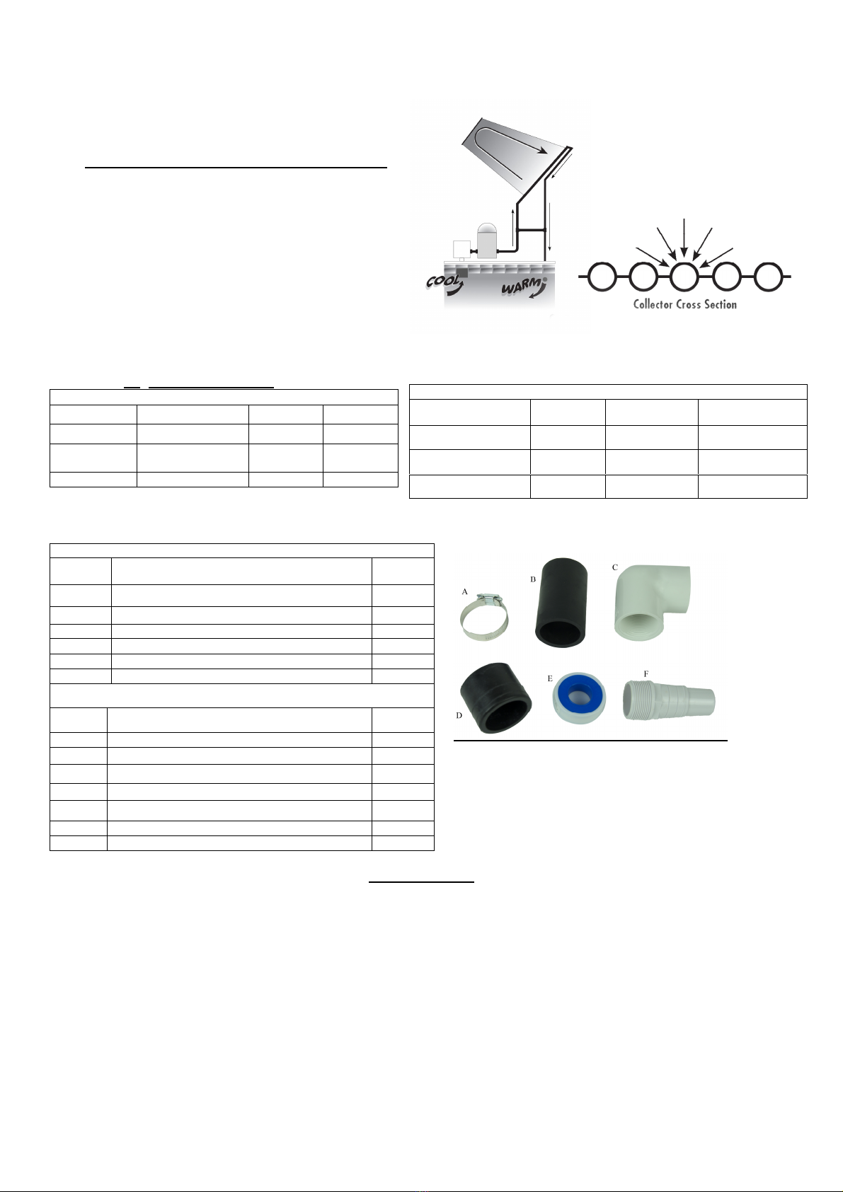
* Allow the collectors to lay in the sun
for 30 minutes to relax the material and
flatten the panels
* Ensure there is at least 1’ around all
sides of the collector(s) for adequate
space for connectors and plumbing.
* Install the collectors on a slight angle
toward and end cap for draining and
winterization.
* The panels can be placed on either side of a roof
vent up to 3” in diameter.
* Ensure the collectors will have at least
6 hours of direct sun exposure.
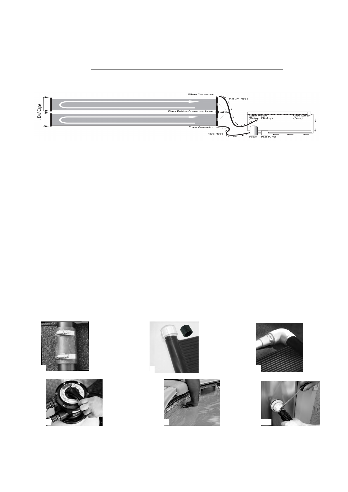
INSTALLATION
NOTE: Below instructions are for mounting
purposes only. For full collector installation,
please see the appropriate system layout provided
in this manual.
1. Once positioning is established, locate the
manufactured slots in the collector (5 slots in a 20’
collector).
2. Place the bracket in place and pre-drill a 1/8 “
pilot hole for the screw.
3. Insert the screw using a phillips head screwdriver to hold the
bracket in place (as shown).
4. Install a bracket on the bottom side of the panel (as shown),
ensuring that the bottom is in line with the top bracket.
NOTE: (15) brackets are provided with each kit, which will
support up to (2) 2’x 20’ collectors. (10) brackets are used for the
top end of each 2’ panel and (5) are used for the bottom of the
second 2’ collector.
5. Once all brackets are installed, use the provided strapping to
hold the collectors in place. Tie a knot in the tip bracket and feed
the strap through the middle bracket before tying the strap bottom
bracket.
(as shown)
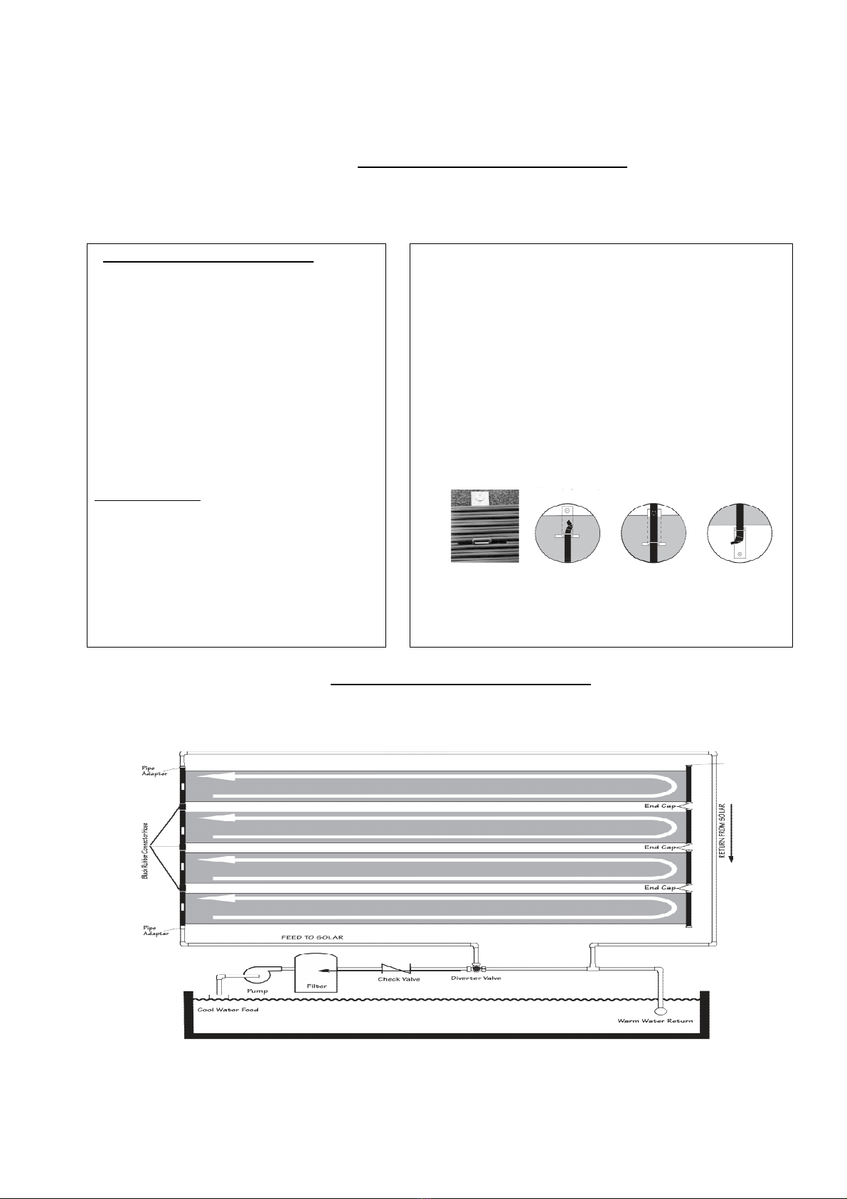
HARD PLUMB SYSTEM LAYOUT
Note: The SM050004 KIT (not included) is required for the following installation.
See page 7 for available kit options

7
WINTERIZATION
YOUR SOLAR SYSTEM MUST BE DRAINED FOR WINTERZATION! FREEZE DAMAGE IS NOT
COVERED UNDER THE MANUFACTURER’S LIMITED WARRANTY! YOU MUST DRAIN YOUR
SOLAR COLLECTORS JUST LIKE YOU DRAIN THE REST OF YOUR POOL EQUIPMENT!
Remove the vacuum relief valve at the top solar system. Remove the rubber end cap at the bottom and be sure ALL the water is
drained out of the system. Replace end caps and blow pressurized air in the reverse direction of normal water flow. This is the
most effective way to drain your system. You can leave the collectors in place (as long as they are completely drained) and they
will withstand even the harshest winters. Sun2Solar recommends that you store your collectors inside in a warm dry place.
COLLECTOR REPAIR
IF A COLLECTOR DEVELOPS A LEAK
Your solar collectors are warranted against defects in materials and workmanship (see warranty for details and limitations). If a
leak develops for any other reason, you may use the repair method shown. The collectors are not warranted against freeze
damage.
SOLAR COLLECTOR REPAIR
This method allows for an easy and permanent, on-site repair of a collector by isolating the leading riser tube. Referring to the
figure at the right, locate the tube to be isolated.Using a sharp utility knife, very carefully cut away approximately 1” (2.54
cm) of the tube at the both headers. Drive #10 sheet metal screw, preferably stainless, into the hole in the header. The screw
must be between ½” (1.27 cm) and ¾” (1.9 cm) long. DO NOT OVER-TIGHTEN! If the screw strips out, or if the repair
leaks, use a #12 screw. This repair method will not void the collector warranty. With proper care and winterization, you will
enjoy your solar collectors for many years.AVAILABLE KITS OPTIONS
SM050004 INGROUND UNIVERSAL SYSTEM KIT
KIT COMPONENTS QTY
1.5” Diverter Valve 1
3.75” Rubber Hose Connector 1
Pipe Adaptor 2
End Cap 1
Vacuum Relief Valve 1
Spring Check Valve 1
1.5” Stainless Steel Clamps 3
*Used for hard plumb installation * Will support up to (8) 2 x 20 systems or (4) 4 x 20
803039 ABOVEGROUND MANUAL DIVERTER VALVE KIT
KIT COMPONENTS
1.5” Ball Valve 1
1.5”PVC Tees 2
Flex Hose Adaptors 4
*Used for flex hose installations* * Will support 2 x 20 and 4 x 20*
803030 MOUNTING KIT
KIT COMPONENTS
6’ Web Strapping 5
Stainless Steel Mounting Brackets 15
#14 Stainless Steel Screws 15
*Used for flex hose installations* * Will support 2 x 20 and 4 x 20*
SM050006 HIGH WIND ADD-ON MOUNTING KIT
Kit Components QTY
6’ Web Strapping 4
Stainless Steel Mounting Brackets 4
#14 Stainless Steel Screws 4
**Use in conjunction with 803030 in areas of excessive wind **will support (1) 2’ x 20” collector**

8
TROUBLESHOOTING
PROBLEMS POSSIBILITIES / SOLUTIONS
Sun2Solar™
Heater does not
appear to be
heating the pool.
*Make sure that water is flowing through Sun2Solar™Heater by checking the flow
at the pool return.
*Note the weather- has it been cloudy or raining?
*Use your pool cover at night to reduce heat loss.
*Refer to our order guide- pool size may require additional collectors.
Bubbles continue to
appear from the
pool water inlet
during operation.
*Check the connections for leaks
*Check the flow rate
*Check the tubing for leaks or clogging.
Sun2Solar™
Heater leaks. *Make sure connectors and hose clamps are tight and not defective.
This manual suits for next models
6
Table of contents
Popular Swimming Pool Heater manuals by other brands

Pentair
Pentair Pool & Spa Heaters NT Series Operation & installation manual

Steinbach
Steinbach Waterpower 5000 user manual

iGenix
iGenix IG9512 Instructions for use

Texsun
Texsun El Niño instructions

Zodiac
Zodiac RE/L Instructions for installation and use

Jandy
Jandy pool/spa heater Installation and operation manual