Sunamp UniQ eHW Series User manual

UniQ eHW Heat Battery Installation and
User Manual
UniQ eHW Heat Batteries Installation and User Manual
Keep these instructions in a safe place for future reference
Keep these instructions in a safe place for future reference.

2
Safety Notice
Symbols and Notices Used and Their Meanings
Symbols
Warning
Electric Hazard
Take note
Cross reference
Warning Notices
Consequences
Likelihood
Death/serious injury (irreversible)
Potential risk
Damage/minor injury (reversible)
Potential risk
DO NOT install outdoors. This product is for indoor use only.
Improper installation, adjustment, alteration, service or maintenance can
cause property damage, injury and death.
ONLY competent persons who are suitably qualified to carry out
plumbing and electrical work and have successfully completed product
training by Sunamp Ltd or an authorised training partner may undertake
installations, repairs or relocations.
The system must be earthed correctly and have its own independent
electrical supply with correct voltage and circuit breakers.
The point of connection to the mains should be readily accessible and
adjacent to the Heat Battery installation. Connection must allow isolation
of the electrical supply. Disconnection must be achieved by a fused spur
in accordance with the wiring rules.
Only use this product for the intended purpose described in this manual.
There are no user serviceable, adjustable or settable parts in this product.
Read the full Safety Instructions in Section 1 of this manual
before you install this product.

3
Document Purpose
To instruct competent persons on how to safely install UniQ eHW Heat Batteries. Competent
persons are those suitably qualified to carry out plumbing and electrical work and have
successfully completed product training by Sunamp Ltd or an authorised training partner.
Contents
1Safety Instructions........................................................................................................4
1.1 Intended Use .........................................................................................................................4
1.2 Pre-installation Safety Advice..............................................................................................4
1.3 Mechanical Safety.................................................................................................................4
1.4 Electrical Safety.....................................................................................................................5
1.5 Water Safety ..........................................................................................................................5
1.6 User Competence, Qualification, and Approval ................................................................6
1.7 Compliance with Safety Laws and Regulations................................................................. 6
1.8 Post-Installation Safety .........................................................................................................7
1.9 Repair and Relocation .......................................................................................................... 7
2UniQ eHW Heat Battery Overview................................................................................8
2.1 Introduction............................................................................................................................ 8
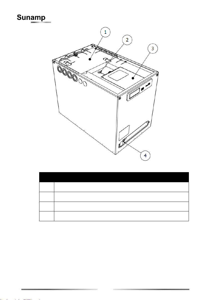
2.2 Product Overview .................................................................................................................9
2.3 Product Identification..........................................................................................................11
2.4 Accessories and Parts........................................................................................................12
2.5 Technical Specifications ....................................................................................................13
2.6 Pressure Loss Characteristics...........................................................................................16
3Installation...................................................................................................................17
3.1 Installation Process.............................................................................................................17
3.2 Water Supply Requirements..............................................................................................20
3.3 Location and Space Requirements...................................................................................21
3.4 Hydraulic Requirements.....................................................................................................23
3.5 Temperature and Insulation Requirements......................................................................23
3.6 Electrical and Wiring Requirements..................................................................................24
3.7 Wiring Option 1 –24h Grid Supply Without Time-Switch..............................................27
3.8 Wiring Option 2 –On-/Off-Peak Tariff with External Time-Switch.................................30
4Commissioning ...........................................................................................................33
4.1 Preparation ..........................................................................................................................33
4.2 Process.................................................................................................................................33
5Operation ....................................................................................................................35
5.1 Switch On/Off ......................................................................................................................35
5.2 LED Indicators and Status..................................................................................................35
5.3 Troubleshooting ..................................................................................................................36
6Maintenance................................................................................................................38
6.1 Removal of Lids...................................................................................................................38
6.2 Cleaning ...............................................................................................................................38
6.3 Warranty...............................................................................................................................39
7Recycling and Disposal ..............................................................................................39

4
1Safety Instructions
Sunamp Ltd is not responsible for the failure of components not
specified in this manual and/or supplied by other manufacturers.
1.1 Intended Use
The intended use of the UniQ eHW range of products is for the
provision of hot water for domestic purposes by means of electric
charging of the Heat Battery. It is not intended for use with other
charging methods or in applications other than the provision of
domestic hot water.
1.2 Pre-installation Safety Advice
•Sunamp Ltd is not responsible for the selection, specification
or effectiveness of equipment, unless stated in writing.
Responsibility lies with customers and any experts or
consultants involved in design and/or installation.
•Where applicable, this manual should be read in conjunction
with manufacturer documentation for any components
specified in the installation requirements of this manual.
•Where necessary, refer to the Sunamp website
(www.sunamp.com) for contact and support information.
1.3 Mechanical Safety
•DO NOT install outdoors. This product is only suitable for
indoor use to avoid weather damage.
•DO NOT tilt the product more than 45 degrees during the
transportation or installation process.
•Install the product on a hard, solid and level surface that
can support its weight.
•DO NOT use detachable hose-sets to connect the system
to water mains.

5
•All hot works (such as soldering, welding or brazing) must be
performed on tubes detached from the heat battery
(minimum 1 metre away).
•This product is NOT suitable for tank fed hot water system.
•Do not immerse this product in water or any other liquid.
1.4 Electrical Safety
•The product must be earthed correctly and have its own
independent electrical supply (with correct voltage and
circuit breakers).
•The point of connection to the mains should be readily
accessible and adjacent to the Heat Battery installation.
•Connection must allow isolation of the electrical supply. The
means of isolation must be accessible to the end user after
installation.
•Disconnection must be achieved by a fused spur in
accordance with the wiring rules.
•Ensure that there is water in the system before switching on
electrical supply.
•All models in this manual are designed for heating by
integrated electric heaters only.
1.5 Water Safety
•Minimum working pressure of Heat Battery is 0.15 MPa / 1.5
Bar. Maximum working pressure of Heat Battery is 1.0 MPa
/ 10 Bar. See section 2.5.2 for detailed specifications.

6
1.6 User Competence, Qualification, and Approval
•ONLY competent persons who are suitably qualified to carry
out plumbing and electrical work and have successfully
completed product training by Sunamp Ltd or an authorised
training partner may undertake installations, repairs or
relocations.
•DO NOT allow children or any other unqualified or
unapproved persons to install, repair, clean, relocate,
interfere or tamper with the product.
•This product is not designed for use by children, or persons
with reduced physical, sensory or mental capabilities, and
should not be used by such persons unless they can do so
safely. Where necessary, such persons (or anyone with lack
of experience or knowledge) should first be given supervision
or instruction concerning use of the product by a person
responsible for their safety.
1.7 Compliance with Safety Laws and Regulations
•Installations, repairs and relocations must comply with all
relevant local laws and regulations (‘statutory obligations’),
particularly concerning electrics, water supplies, building
regulations and Manual Handling Operations, as issued by
the Government Health and Safety Executive (‘HSE’). Water
distribution and central heating installations (‘systems’) must
comply with all statutory obligations.
•Statutory obligations always override manufacturer
documentation where there is a conflict.

7
1.8 Post-Installation Safety
•All goods are sold subject to Sunamp Ltd’s ‘Conditions of
Sale’, as listed on the company website.
•As Sunamp Ltd continuously improves products, they may be
modified without notice. In such circumstances this manual
and other relevant documentation should be disregarded.
Updated documentation will be produced, supplied with new
product ranges and made available on request.
•Once installed:
oPerform a test run to ensure normal operation.
oExplain all safety precautions to the end user.
oProvide a copy of this manual to the end user.
•It is the responsibility of the end user to supply this manual to
any other subsequent users.
1.9 Repair and Relocation
•DO NOT attempt to carry out repairs or maintenance before
the system components –including the UniQ eHW Heat
Batteries - have cooled down to ambient room temperature.
To speed up the process, disconnect power supply and open
hot water taps in the dwelling to draw off hot water and cool
system down.
•DO NOT attempt to move an assembled system without using
appropriate lifting equipment.
•There are no user serviceable, adjustable or settable parts in
this product.
SAVE THESE INSTRUCTIONS AND
PROVIDE A COPY TO THE END USER.

8
2UniQ eHW Heat Battery Overview
2.1 Introduction
Thank you for choosing a Sunamp Ltd UniQ Heat Battery, our innovative,
super-compact heat storage system based on phase-change materials
(PCM). We are sure you will be delighted with the performance,
compactness, ease of installation and quality of our product.
Sunamp Ltd’s decade-long history of research and innovation in PCM
technology has made it the world-leading manufacturer in Heat Battery
technology –developed, designed and manufactured in the UK.
Sunamp Ltd has a wide portfolio of Heat Batteries for different applications.
Please visit our website (www.sunamp.com) or look at our catalogue for
more information about our portfolio for:
•Water heating
•Space-heating
•Combined space- and water-heating
•Cooling
The Sunamp Ltd UniQ eHW Heat Batteries are:
•Designed to produce domestic hot water and are heated directly by grid
electricity only.
•Equivalent to direct electrically heated hot water cylinders and hot water
only thermal stores.
•Heated by internal electric heating elements only, and therefore able to
replace direct unvented cylinders.
•Classified as a Primary Thermal store. By transferring heat from the
PCM to the mains water flowing through the heat exchanger, they
produce hot water instantaneously and on demand.
•Class I stationary appliances that use a single-phase electrical supply.
See the downloads section of our website (www.sunamp.com) for other
useful information on Sunamp Ltd products.

9
2.2 Product Overview
Figure 1: Heat Battery (external)
Item
Description
1
Heat Battery –main body
2
Heat Battery –lid
3
Data badge / serial number
4
Controller interface
5
Terminal cover plate
6
Tube entries (3 sides)
7
Cable entries (3 sides)
8
Energy label –to be applied by installer (if applicable)
Table 1: Product overview (external)

10
Figure 2: Heat Battery (internal)
Item
Description
1
Insulation layers –to be cut to suit copper tube and cable entries
2
Temperature sensor
3
Electrical control box –PCB, relays, terminal block
4
Non-self-resetting overheat thermostat (OHT)
Table 2: Product overview (internal)

11
2.3 Product Identification
Figure 3: Heat Battery views showing the three tube exits
Item
Description
Item
Description
1
Earth Clamp (supplied) - to be
clamped to Ø22mm copper tube
4
Cable Entry via Gland - supplied but
not fitted
2
Cold Water Inlet –‘A’ – Ø22mm
elbow –rotatable 360 degrees
5
Ø22mm Copper Tube to
BSEN1057 - suitable for installation
(not supplied)
3
Hot Water Outlet –‘D’ - Ø22mm
elbow –rotatable 360 degrees
Tube and cable entries are used
depending on installation location
Table 3: Product installation options

12
2.3.1 LED Interface
Figure 4: LED interface
Item
Description
D4
Mains power LED
D3
Charge level status LED
D2
Charge level status LED
D1
Heater ‘Active’ LED
Table 4: LED interface
2.4 Accessories and Parts
Part Number
Description
C5388
Thermostatic Mixing Valve (TMV)
C5034
Expansion Vessel 0.5L
C5381
Water conditioner
C5377
22mm Tectite Pro Elbow TX12 65524 (see note)
C5379
22mm Tectite Pro Tee TX24 65676
C5412
Conex BM8090 0220000 22mm >B<Push elbow
Table 5: Accessories
Note: 2 x C5377/C5412 are supplied with the product as standard. Visit our website
(www.sunamp.com) for all the latest accessories and spare parts.

13
2.5 Technical Specifications
2.5.1 Basic Specifications
Battery Model
Height
(mm)
Depth
(mm)
Length
(mm)
Gross
Weight
(kg)
Net
Weight
(kg)
UniQ eHW 3
429
365
575
72
70
UniQ eHW 6
630
130
125
UniQ eHW 9
856
182
175
Table 6: Model specific dimensions. Net Weight refers to an empty Heat Battery (i.e. no water
in the tubes); Gross Weight refers to tubes being filled with water.
Figure 5: Additional Sunamp Ltd UniQ eHW Heat Battery dimensions
Item
Description
Item
Description
1
Length: See Table 6
4
Tube Entry: 37mm
2
Depth: See Table 6
5
Tube Entry: 78mm
3
Height: See Table 6
6
Tube Entry: 50mm
Table 7: Common product dimensions

14
2.5.2 Detailed Specifications
Specification
Size 3
Size 6
Size 9
See Note
Heat storage capacity (kWh)
3.5
7.0
10.5
1
Water Content (L)
2.3
4.5
6.8
2
Equivalent Hot Water Cylinder Size (L)
71
142
212
3
V40, Volume of Hot water available at 40°C (L)
85
185
300
4
Standby heat loss rate (kWh / 24h | (W))
0.48 | (20)
0.67 | (28.1)
0.77 | (32.1)
Energy efficiency rating class
C
6
Recommended maximum HW flow rate (L/Min)
6
15
20
Minimum mains supply pressure at inlet of Heat Battery (MPa | (Bar))
0.15 | (1.5)
Maximum working pressure (MPa | (Bar))
1.0 | (10)
Pressure loss characteristics KVValues
Figure 6.1 (Section 2.6)
Hot water outlet temperature at design flow rate (°C)
45-55
5
Connected load at ~ 230 V, 50Hz (W)
2,800
Power supply | Standby consumption (W)
1 PH ~ 230 V | 7
Electrical efficiency (ηelecwh) (%)
81.4
89.6
93.8
7
Annual electricity consumption (AEC) (kWh/annum)
542
1,398
2,690
Tapping cycle
S
M
L
Table 8: Detailed specifications for UniQ eHW Heat Battery models

15
Notes to Table 8:
1. Heat Battery charged to design charge temperature TC (75°C) and then
discharged using inlet discharge water temperature TD(10°C) until the
outlet water temperature dropped to 40°C.
2. Water content of the Heat Battery for sizing expansion vessels.
3. Calculated from the storage capacity of the Heat Battery and assuming
that the equivalent hot water cylinder thermostat is set at 60°C, mains
cold water inlet temperature is at 10°C, the hot water outlet temperature
is set at 40°C and the stored hot water utilisation factor of the cylinder
is 0.95.
4. The hot water volume available from the Heat Battery at average outlet
temperature of 40°C when it is charged to 75°C, tested to standards:
•BS EN 12897:2016+A1:2020 Water Supply. Specification for
indirectly heated unvented (closed) storage water heaters.
•BS EN 60379-2004 Methods for measuring the performance
of electric storage water-heaters for household purposes.
5. Recommended setting range for hot water thermostatic mixing valve.
6. When installed as an electric water heater.
7. Tested to standard: BS EN 50440:2015
For more detailed specifications, also see the UniQ Heat Batteries
General Product Application and Design Manual, available from the
downloads section of our website (www.sunamp.com).

16
2.6 Pressure Loss Characteristics
Pressure loss characteristics can be calculated using the graph below
(Figure 6.1). The points that the pressure loss for the Heat Battery are
displayed in (Figure 6.2)
Figure 6.1: UniQ eHW Heat Battery pressure loss characteristics graph
Figure 6.2: Pressure loss at inlet & outlet of the Heat Battery
0
0.05
0.1
0.15
0.2
0.25
0.3
0.35
0.4
0 5 10 15 20 25
Pressure Loss (Bar)
Flow Rate (L/min)
Size 3
Size 6
Size 9

17
3Installation
Always read the safety instructions in Section 1 of the manual before
installing UniQ eHW Heat Batteries.
3.1 Installation Process
Preparation:
•Assess the location of installation considering spatial requirements,
clearances, cable runs and tube runs.
•Unpack and discard or recycle packaging according to local disposal or
recycling rules.
•Identify which side you wish to make hydraulic and electrical cable
entries (see Figure 3 in Section 2.3).
•Prepare the system hydraulics and electrics.
•Lift unit into position using appropriate lifting methods.
Hydraulic Connection:
Note:- Cold water inlet connects to port A; hot water outlet connects to port
D (Figure 6.2).
•Remove lid. The lid is secured by 2 x M5 button head cap screws at the
front and two locating pins at the back (Figure 7):
oRemove 2 x M5 button head cap screws using 3mm hex head
and set aside.
oSlide the lid forward, then lift the lid up and set aside.
•Remove the top two layers of insulation (layer 1 is 10mm and layer 2 is
32mm thick) and set aside.
•Rotate the elbows to the side you wish to connect the hydraulics (left,
right or back).
•Remove the respective rubber grommets in the outer housing and cut
the centres (with a cross) with a knife. Reinsert the cut grommets.
•Cut and prepare the two off lengths of Ø22mm copper tube to suit the
rest of the installation/system:
oAlways cut the tube square, using a rotary tube cutter whenever
possible. Ensure the cutter wheel is appropriate for the copper
tube.

18
oDeburr the tube end, both internally and externally to create a
1mm chamfer on the outside of the tube.
oCheck the tube ends are free from damage and clean, wiping
away any swarf to avoid damaging the ‘O’ ring on tube insertion.
oTube end must also be free from stickers, tape and adhesive
residues.
oMark the socket depth (27mm) on the tube with a marker.
oInsert the tube firmly with a slight twisting action until it reaches
the tube stop with a positive ‘click’.
oEnsure the depth insertion mark corresponds with the mouth of
the fitting, then pull the tube firmly to ensure the fitting is secure.
•Fit the earth clamp to the Ø22mm copper tube (See Figure 3 in Section
2.3).
•Connect to the rest of the fixed system hydraulics.
•Fill the system with water, purging any air out of the system. This may
take several minutes and can be aided by repeatedly opening and
closing the outlet.
•Once finished purging and with the system pressurised, inspect the
piping/tubing and joints for any leaks. Take remedial action if necessary.
Electrical Connections:
•Move the cable strain relief fittings to the side you wish to make the
entries/exits. Cover all other holes in the enclosure with the supplied
blanking grommets (Figure 8).
•Feed the mains cable through the strain relief bushing in the heat
battery housing.
•If applicable, feed the signal cable through the additional strain relief
fittings.
•Line up the cable strain relief fitting ratchet feature and compress firmly
so that the fitting grips the cable.
•Open the internal controller enclosure using a flat head screwdriver to
remove the snap in’ lid.
•Connect the wires according to the wiring options if not already fitted.
•Remove or make links according to the wiring options.
•Close up the internal controller enclosure replacing the ‘snap fit’ lid and
check the earth clamp on the copper tube is secure.

19
Final Fit After Commissioning:
Commissioning instructions are provided in Section 4 of this manual. Follow
the instructions below after commissioning.
•Cut the 32mm thick insulation layer to suit the tube and cable entries.
This layer has several perforations for guidance. This can be done with
a sharp knife or scissors.
•Replace the newly cut 32mm thick insulation layer nesting the insulation
around the tube work and cables. Makes sure the main and signal
cables sit above this layer.
•Replace the top 10mm layer of insulation.
•Replace the lid, aligning the rear pins with the slots in the rear of the
unit, slide back, fit the 2 x M5 button head cap screws using 3mm hex
head.
Figure 7: Access to Heat Battery connections
Item
Description
1
Remove fasteners x2 using 3mm Allen Key
2
Slide lid forward
3
Lift lid
Table 9: Access to Heat Battery connections

20
Figure 8: Cable and tube interfaces
Item
Description
1
Cable entry strain relief gland
2
Cable entry blanking bush
3
Tube entry grommet
Table 10: Cable and tube interfaces
3.2 Water Supply Requirements
Important: All components fitted in the water system should be Water
Regulations Advisory Scheme (WRAS) approved.
3.2.1 General
For information regarding expansion vessel sizing and pressure relief
valves, refer to the UniQ Heat Batteries Reference Manual, available from
the downloads section of our website (www.sunamp.com).
Important: Although the Heat Batteries are designed for 1.0MPa (10 bar)
maximum working pressure, it is recommended that if the incoming mains
pressure is greater than 0.5MPa (5 bar), a WRAS approved pressure
regulator set at 0.5MPa (5 bar) should be fitted.
•Mains cold water supply should be connected to Heat Battery
connection ‘A’. The hot water outlet should be connected to ‘D’ (see
Figures 3, 12.1 and 13.1).
•DO NOT use detachable hose-sets to connect the product to the water
mains.
This manual suits for next models
3
Table of contents
Other Sunamp Camera Accessories manuals
Popular Camera Accessories manuals by other brands

Bosch
Bosch PowerTube 750 Series Battery guide

Delta Regis
Delta Regis ESB-10VL2500 Operation manual

True blue power
True blue power TB44 series Installation manual and operating instructions

Sanyo
Sanyo Cadnica N-2U Specifications

Franke & Heidecke
Franke & Heidecke Rolleiflex Hy6 user manual

UPG
UPG Consumer Battery Solutions brochure