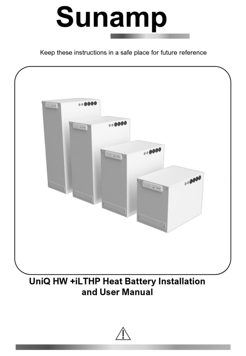
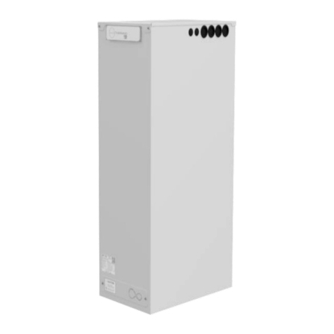
Sunamp UniQ HW +i-VT Installation and operating instructions

UniQ HW +i-VT & UniQ HW +iPV-VT Heat
Batteries Addendum Manual
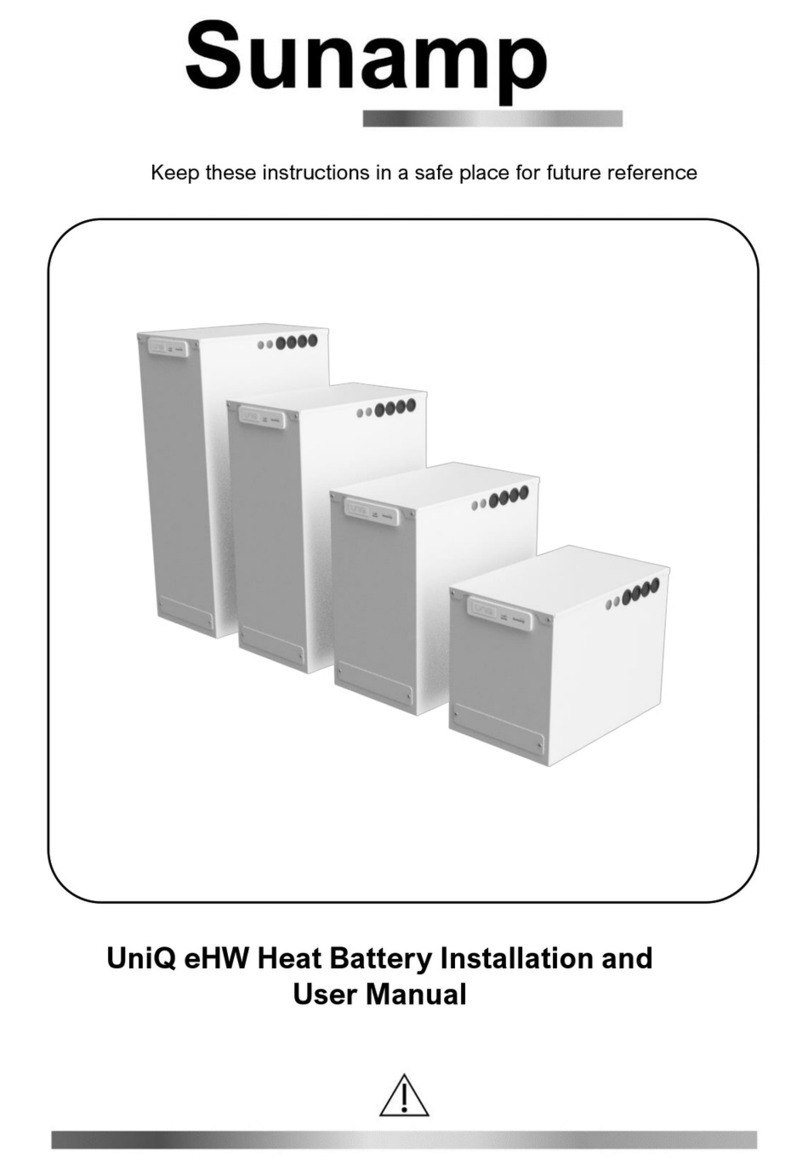
UniQ eHW Heat Batteries Installation and User Manual
Keep these instructions in a safe place for future reference
Keep these instructions in a safe place for future reference.

2
Safety Notice
Symbols and Notices Used and Their Meanings
Symbols
Warning
Electric Hazard
Take note
Cross reference
Warning Notices
Consequences
Likelihood
Death/serious injury (irreversible)
Potential risk
Damage/minor injury (reversible)
Potential risk
This Addendum manual MUST be followed for Sunamp UniQ Heat
Batteries installations with Vaillant Arotherm Plus High Temperature
Heat Pumps. This manual should be read in conjunction with the
Sunamp UniQ HW+i or HW+iPV Heat Batteries Installation and User
Manual.
This Addendum manual ONLY contains relevant information on how
to setup the hydraulics and electrics, between the Heat Battery and
the Vaillant Arotherm Plus Heat Pump for the install and what
settings should be applied to the Vaillant Arotherm Plus, Heat Pump
Interface and Sensocomfort controls. This is to allow the correct
control configuration between the Sunamp UniQ Heat Battery and
the Vaillant Arotherm Plus.
Please note that Sunamp takes no responsibility for any other
system configuration and installation other than what is
documented in this Addendum manual.

3
Contents
Safety Notice..........................................................................................................................2
1Sunamp UniQ HW +i-VT................................................................................................4
1.1 Sunamp UniQ HW +i-VT controller wiring diagram ..........................................................4
1.2 Sunamp UniQ HW +i-VT wiring...........................................................................................5
1.2.1 Electric override switch wiring................................................................... 5
1.2.2 External heat source sensor cable wiring ................................................ 6
1.3 Sunamp UniQ HW+i-VT hydronics and controls schematic ............................................7
2Sunamp HW +iPV-VT.....................................................................................................9
2.1 Sunamp UniQ HW +iPV-VT controller wiring diagram .....................................................9
2.2 Sunamp UniQ HW +iPV-VT wiring....................................................................................10
2.2.1 External heat source sensor cable wiring .............................................. 10
2.3 HW+iPV-VT hydronic and controls schematic ................................................................12
3Vaillant heat pump settings ........................................................................................14
3.1 Vaillant Sensocomfort settings..........................................................................................14
3.2 Vaillant Heat Pump Interface settings...............................................................................15
4Other Information .......................................................................................................15

4
1Sunamp UniQ HW +i-VT
1.1 Sunamp UniQ HW +i-VT controller wiring diagram
Figure 1: Internal controller wiring diagram (wire sizes=0.75mm2, unless stated
otherwise)

5
1.2 Sunamp UniQ HW +i-VT wiring
Important: Please follow (Table 1) for information regarding the Links.
Link specification
Removed or Fixed
Link 1
Fixed (Factory Setting)
Link 2
Fixed (Factory Setting)
Table 1: Wiring HW +i-VT –Link 1 & 2 settings
Link 3 will be provided fixed within the product; for this product type it MUST
remain in place. Removing the Link 3 will result in increased consumption
and running times of the Vaillant Arotherm Plus Heat Pump.
•Run and connect 3 Core mains power supply cable (16A, minimum
2.5mm2CSA) from the local 2-pole isolator to the Heat Battery
controller (Figures 2 and 3).
•Wire the cable via the appliance case grommets and into the control
box housing (UniQ HW+i installation manual Figure 8 and Figures 2 and
3 below).
•Prepare if necessary and wire the mains power cable in the following
terminals (UniQ HW+i installation manual, Figure 10 and Figures 2 and
3 below):
oBrown (Live): Terminal L1 (Live)
oBlue (Neutral): Terminal N1 (Neutral)
oGreen/Yellow (Earth): Terminal PE (Protective Earth)
1.2.1 Electric override switch wiring
•Wire a 2 core shielded PVC insulated cable (minimum 0.75mm² CSA,
24 x 0.2mm according to BS 6500) from a 2-pole Volt-free contact
switch, run the wire into the appliance via the appliance case cabling
grommets and then into the control box housing through the hole
available. Secure the cables in Terminal T1 & T2 independently (Figure
2 & Figure 3).
Warning: Please DO NOT connect a fused spur for this connection.
Note: This switch should be off by default. Engaging this switch will put
the Heat Battery into electric charging mode only and disable the
function of the Vaillant Arotherm Plus Heat Pump until the switch is set
to off. This can lead to increased electricity consumption, resulting in
higher energy costs. This should be explained to the end user and the
switch labelled accordingly.

6
1.2.2 External heat source sensor cable wiring
•Wire a 2 core PVC insulated cable (minimum 0.75mm² CSA, 24 x
0.2mm according to BS 6500), the heat battery controller in this
application acts as hot water thermostat. The cable will act as a hot
water heating tank sensor from the heat battery controller terminals T3
& T4 into the Vaillant Heat Pump Interface controller SP1 screw
terminals 1&2 (please refer to Vaillant Arotherm Plus Installation
manual). Please run the wire into the heat battery appliance via the
appliance case cabling grommets and then into the control box housing
through the hole available. Secure the cables in Terminals T3 & T4
independently (Figure 2).
White Case
Controller Case
Link 2
Link 1
2.5 mm2 , 3 Core HT Flex
Local 2 Pole 16A Isolator
L2 N1
~230V, 16A supply
Live Neutral Earth
Electric override
switch (Volt-free)
N2 1
L1 2 3 4
Vaillant Arotherm
Plus Hot Water
control to VRC 700
SP1 1&2.
Strain Relief
Figure 2: HW +i-VT system wiring

7
1.3 Sunamp UniQ HW+i-VT hydronics and controls schematic
6
5
T
3
7 8
9
15
2
18
13
16
17
1
Heating
demand
19
12
14
11 10
10
20*
D
4
Figure 3: Example wiring option 1.2 schematic (see UniQ HW+i installation manual,
Figure 3 for piping and electrical exit options available)
Item
Description
1
Vaillant Heat
Pump
Interface
7
Central
Heating Flow
13
Mains Water
Expansion
Relief Valve
2
Circulation
pump (*)
8
Central
Heating
Return
14
Hot Water
Tempering
Valve

8
3
Diverter Valve
(Normally
Open to
Heating)
9
Check valve
15
Hot Water flow
regulator
4
Vaillant
Heating
Thermistor
10
Mains Cold
Water
Supply
16
230VAC 16 A
power supply
5
Flow from
Heat Pump to
Heat Battery
11
Hot water
supply to
dwelling
17
Local 2-pole
Isolator, 16A
6
Return to Heat
Pump from
Heat Battery
12
Expansion
Vessel
18
Cold Water
Mains Pressure
regulator
19
Electrical supply from Dwelling
consumer board ~230V AC,
16A
20
Auto-bypass valve
Notes: * The circulation pump is located in the Heat Pump enclosure and
is controlled by the heat pump controller.
Table 2: Explanation of components for HW +i-VT

9
2Sunamp HW +iPV-VT
2.1 Sunamp UniQ HW +iPV-VT controller wiring diagram
All wire sizes in 0.75mm²,
unless stated differently
S3 = Green
S1 = Blue
S0 = Yellow
S2 = Red
1
2 4 8
0
8
2.5mm2
L
J1
2 4 6 8
0 1
2.5mm² HT cables: To
heating element via OHT
L1 L2 N1 N2 1 2 3 4
SW Version
Serial No.
0
8
RS4RS5
A1
A2
2 4 3
Link 3
Relay 2
Relay 1
Link 2
TYPE 2_VT
Ingress to Control box
N
Sensor
Cable 2.5mm2 Earth
to Outer Case
Figure 4: Internal controller wiring diagram (wire sizes=0.75mm2, unless stated
otherwise)

10
2.2 Sunamp UniQ HW +iPV-VT wiring
Important: Please follow (Table 3) for information regarding the Links.
Link specification
Removed or Fixed
Link 1
Removed (Factory setting)
Link 2
Fixed (Factory setting)
Charge Link
Fixed (Factory setting)
Table 3: Wiring HW +iPV-VT –Link 1 & 2 settings
Link 3 will be provided fixed within the product; for this product type it MUST
remain in place. Removing the Link 3 will result in increased consumption
and running times of the Vaillant Arotherm Plus Heat Pump.
•Run and connect 4 Core mains power supply cable (16A, minimum
2.5mm2CSA) from the Solar Power Diverter to the Heat Battery. (UniQ
HW+iPV installation manual, Section 3.9 and Figures 5 and 6 below).
•Wire the cable via the appliance case grommets and into the control
box housing (UniQ HW+iPV installation manual, Figures 8 and Figures
5 and 6 below).
•Prepare if necessary and wire the mains power cable in the following
terminals (UniQ HW+iPV installation manual, Figure 10 and Figure 5 and
6 below):
oBrown (Live): Terminal L1 (Permanent Live)
oBlack (Live): Terminal L2 (Modulating Live)
oBlue/ Grey (Neutral): Terminal N1 (Neutral)
oGreen/Yellow (Earth): Terminal PE (Protective Earth)
2.2.1 External heat source sensor cable wiring
•Wire a 2 core shielded PVC insulated cable (minimum 0.75mm² CSA,
24 x 0.2mm according to BS 6500), the heat battery controller in this
application acts as hot water thermostat. The cable will act as a hot
water heating tank sensor from the heat battery controller terminals T3
& T4 into the Vaillant Heat Pump Interface controller SP1 screw
terminals 1&2 (please refer to Vaillant Arotherm Plus Installation
manual). Please run the wire into the heat battery appliance via the
appliance case cabling grommets and then into the control box housing

11
through the hole available. Secure the cables in Terminals T3 & T4
independently (Figure 5).
Link 2
Local 2
Pole 16A
Isolator
White Case
Controller Case
L1 L2 N1
~230V,
16A
supply
Permanent Live
Neutral Earth
2.5 mm2 , 4 Core HT Flex
N2
Solar PV Power Diversion
Contoller
Modulating Live
Surplus PV
power signal
3 41 2
Charge Link
Vaillant Arotherm
Plus Hot Water
control to VRC 700
SP1 1&2.
Figure 5: HW +iPV-VT system wiring

12
2.3 HW+iPV-VT hydronic and controls schematic
5
6
T
3
4
7 8
9
15
2
18
13
19
17
1
Heating
demand
16
12
14
11
10
10
20*
D
Figure 6: Example wiring option 2.2 schematic (see UniQ HW+iPV installation manual
Figure 3a for piping and electrical exit options available)
Item
Description
1
Vaillant Heat
Pump
Interface
controller
7
Central
Heating Flow
13
Mains Water
Expansion
Relief Valve
2
Circulation
pump (*)
8
Central
Heating
Return
14
Hot Water
Tempering
Valve

13
3
Diverter Valve
(Normally
Open to
Heating)
9
Check valve
15
Hot Water flow
regulator
4
Vaillant
Heating
Thermistor
10
Mains Cold
Water
Supply
16
230VAC 16 A
power supply
5
Flow from
Heat Pump to
Heat Battery
11
Hot water
supply to
dwelling
17
Solar Power
Diverter
6
Return to Heat
Pump from
Heat Battery
12
Expansion
Vessel
18
Cold Water
Mains Pressure
regulator
19
Electrical supply from Dwelling
consumer board ~230V AC,
16A
20
Auto-bypass valve
Notes: *The circulation pump is located in the Heat Pump enclosure and
is controlled by the heat pump controller.
Table 4: Explanation of components for HW+i-VT

14
3Vaillant heat pump settings
Before making changes to the Vaillant Arotherm Plus Heat Pump
controllers, first ensure that you have properly reviewed the previous
sections of this Addendum manual and the Sunamp UniQ HW+i & HW+iPV,
particularly in regard to Heat battery specifications as well as location,
electrical supply and water supply requirements. This supported with the
Vaillant Arotherm Plus Heat Pump Installation manual provided with the heat
pump.
3.1 Vaillant Sensocomfort settings
In the Installer level menu please apply the following settings for DHW
settings ONLY (please check Vaillant Arotherm Plus Sensocomfort
installation and user manual),
Setting
Value required
Max cylinder charging
time.
120 minutes
Cylinder charging anti-
cycling time: min
Minimum setting
DHW target
temperature
70°C
Cylinder charging
hysteresis
5K
Cylinder charging
offset
5K
Anti-legionella. Day &
time
OFF
Table 5: Vaillant Sensocomfort settings
NOTE: If following a DHW daily timed schedule, please ensure that a
minimum time window in line with the chosen heat battery and heat pump
capacities is chosen and that potential defrost cycles during this window are
accounted for.

15
3.2 Vaillant Heat Pump Interface settings
Change Heat pump Compressor output in DHW mode from Eco to Normal,
this is available in the DHW settings of the Heat Pump Interface (please
check Vaillant Arotherm Plus installation and user manual).
4Other Information
Please refer to the Sunamp UniQ HW+i or HW+iPV Installation and User Manuals for
other information regarding the Heat Battery Installation, such as: Maintenance,
Troubleshooting, Commissioning, Warranty and Recycling.
This manual suits for next models
1
Table of contents
Other Sunamp Camera Accessories manuals
Popular Camera Accessories manuals by other brands

THOMSON
THOMSON LDK 100 Technical manual

Regal Electro
Regal Electro BA BATEQ4 Operation manual

Arca-Swiss
Arca-Swiss Cube quick start guide

Deka
Deka Unigy II AVR45 Series Installation and operation manual

Baumer
Baumer VCXG.I r IP65/67 HA operating manual

Hypertec
Hypertec CamPocket Focus D7998KHY Specification sheet