Suncast Keystone Garage User manual

Keystone Garage
Assembly Manual
© Suncast Corporation
Toll Free: 866.768.8465
Hours: 9-5 Monday-Friday EST
Kit ships as shown
14x24 Garage

Find the assembly manual for this product at
www.HomePlaceStructures.com/manuals
AMISH ORIGINAL
KEYSTONE 14x24 GARAGE
specifications
This flexible building includes an optional heavy-duty floor, 2x4 construction, steep A-frame
roof style, insulated raised-panel steel house doors, dentil molding and keystone trim
pieces, 4 slider windows with screens and shutters, 4 flower boxes, and screened wood
vents. Can be built with or without customer-supplied garage door.
2 Large Wrought
Iron Flower Hooks
Boxed in
12” Gables
Factory Primed Trim
Diamond Plate Threshold
Factory Primed Siding
(Ready for Customer Supplied Paint)
Extra Strong 7’ High
Front and Back Walls
Optional Garage Door
(Supplied by Customer)
Screened Wood Vents
1 Door Keystone Trim Piece
4 Window Keystone
Trim Pieces
Fancy Dentil Molding
Assembled
Peak Height - 11’ 9”
Double Plywood
Gussets
Optional Vented Cupola with Copper Roof
Rafter Ties
2x4 Rafters 16” O.C.
1/2” OSB Sheathing
Steep A-Frame Roof
Shingles
(Supplied by Customer)
Four Large
30x36 Aluminum
Slider Windows
(with screens)
Four Vinyl
Flower Boxes
Real Lock Set
Black Antique Hinges
Four Sets of
Vinyl Shutters
2x4 Sill Plate
24’
wide
Insulated Raised Panel Double House Doors
(Doors can be placed on either end or the front)
13’8”
deep
3/4” Exterior Grade 5-Ply Decking
(with optional floor)
Sidewalls 2x4s 16” O.C.
Treated Bottom Plate
(if purchased without floor)
Treated 2x4 Wood Ramp
(with optional floor)

Keystone Garage
Assembly Manual
© Suncast Corporation
revised 10/25/06
Please read through the entire manual before starting!
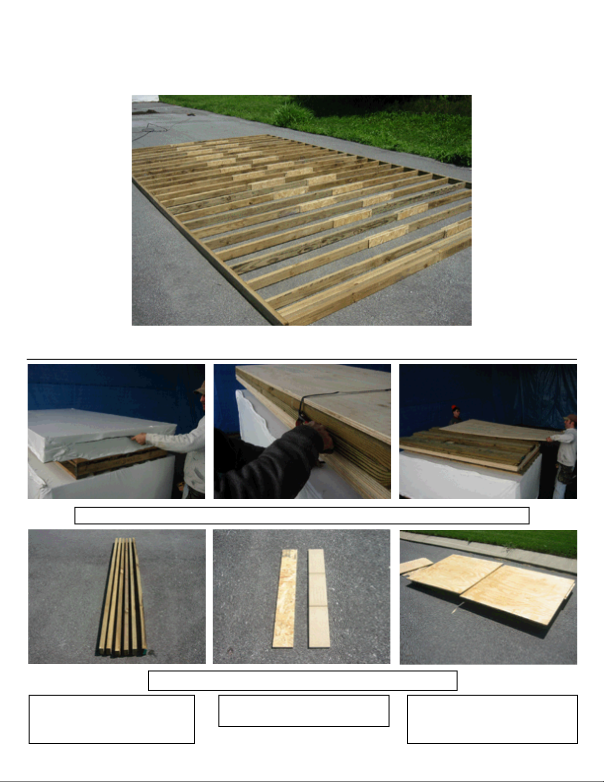
Note: It is very important that you have a solid, level site for the garden building. If the structure
is being used as a garage for automobiles or other heavy items, the unit must be assembled on
a concrete pad.
When using tools and ladders always follow manufacturer’s recommended safety guidelines!
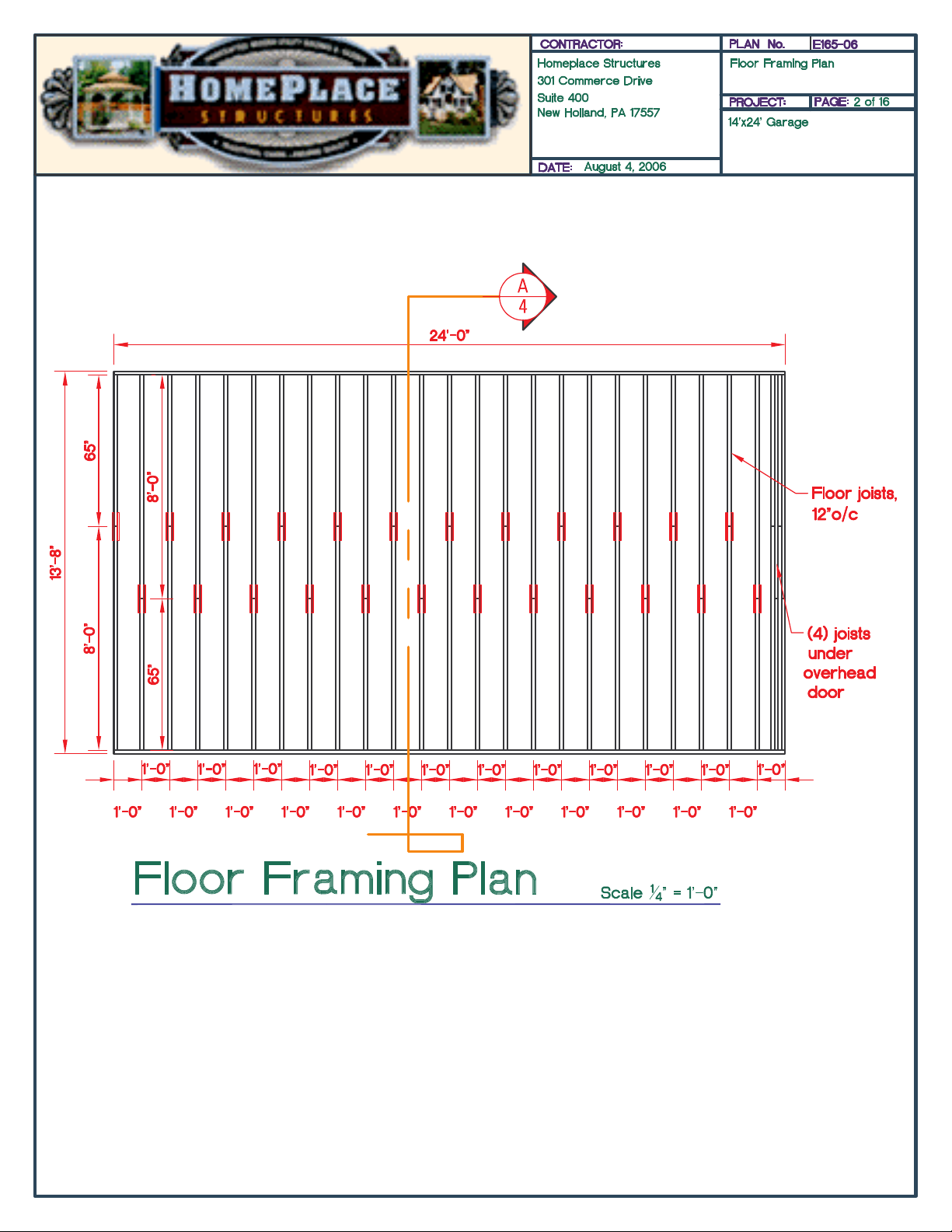
For proper layout for floor, walls, and roof, please refer to the drawings included throughout
this manual and the set of engineered drawings included at end of manual. The pictures shown
in this manual may depict a different layout, if discrepancies occur always refer to drawings.
Tools Needed:
Level
Screw Gun
Hammer
Tape Measure
Skill Saw
Square
Chalk Line
Pencil
5/16” Drill Bit
Tin Snips
Caulking Gun
Other Items Needed:
Approximately 8 gallons of paint
Approximately 20 Bundles of shingles
Heavy duty Silicone Caulk/Sealer
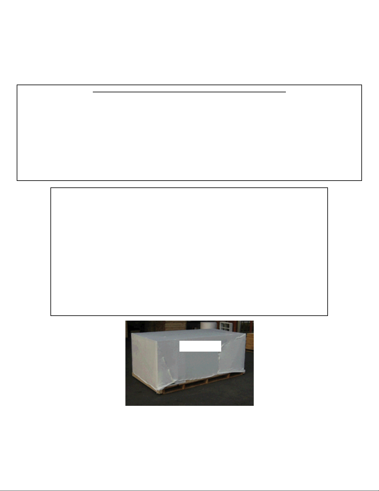
When your kit arrives, it should look like this.
Inspect the package for any damage that
may have occurred during shipping - dented
corners, punctured plastic, etc. If the pack-
age is damaged, alert HomePlace Structures
immediately - 717.354.2333
14x24 Garage

Hardware & Fasteners
3” 12d Nails
Color Code: Fluorescent
Green
Page 4
2-1/2” 7d Nails
Color Code: Pink
2” 6d Nails
Color Code: Orange
2” Trim Nails
Color Code: Fluorescent
Yellow
1-1/2” Red Shutter Screws
Color Code: Dark Blue
2” Black Hinge Screw
Color Code: Black
1” Pan Head Window Screws
Color Code: Light Blue
1” Roofing Nails
Color Code: Purple
The following fasteners are included with your kit. However, you will find the assembly process to pro-
ceed much faster when using air powered tools and fasteners. When replacing hand fasteners with air
powered fasteners, always use a fastener equivalent.
Note: The universal name for nail thickness is penny, abbreviated d. If you wish to purchase additional
nails at your local supplier, use this terminology to find the appropriate nails.
© Suncast Corporation

Page 5
Note: It is important to position 4 joists at end wall underneath
overhead garage door location - overhead door can be positioned on
either end wall.

Optional Floor Assembly
Step 1: Cut open floor kit, cut metal bands, and remove top plywood sheet as shown.
Your floor kit should include all of the following parts:
Page 6
© Suncast Corporation
See drawings on previous page for correct layout.
If you did not purchase the optional floor, please proceed to page 8.
Pressure Treated 2”x4”:
34 - 8'
28 - 65”
OSB pieces:
48 - 3-1/2" x 23-1/2"
5/8” Plywood Flooring
8 - 4’x8’ sheets, 2 - 4'x4' sheets
2 - 20"x8', 2 - 20”x4’

Step 2: Layout six 8’ pressure treated 2”x4” floor plates, square joists at one end, and mark off for floor
joists at 12” on center as shown.
Step 3: Layout floor as shown.
Note: See attached drawing
for correct layout.
Step 9: Fasten plywood sections to floor joists using 7d 2-1/4” galvanized nails spaced 8” apart. Note: It
is important to properly align plywood at edges.
Step 4: Attach short floor joists
to long floor joists using using 6d
2” nail and OSB pcs, keeping all
pieces flush at top.
Step 5: Attach floor joists togeth-
er at appropriate measurements
using two 12d 3” nails per joist
Step 6: Attach outside band-
board joists together as shown.
Step 7: Make sure floor is
square. Floor is square when
diagonal measurements are
equal (approximately 27’5/8”).
Step 8: Layout plywood floor
sections as shown.
page 7
© Suncast Corporation
Tip: It is
important
to level
floor
before
proceed-
ing to
next
step.

Bottom Wall Plate Layout
for Units without floor
Step 10: Cut open large package and remove packing materials repeating step 1.
Step 11: Remove top layer of
4’x8’ OSB roof sheeting and
place to the side.
Note: Unpack kit all the way
down to layer 5.
Note: If you purchased the optional floor, please proceed to back wall layout and assembly page.
Step 12: Remove next layer of
kit and set aside.
Step 13: Remove screws from
4’-2”x4” double wall plates and
set aside.
Step 14: Remove all remaining
pieces (excluding pressure treat-
ed 2”x4” bottom wall plates)
Step 15: Measure a square
pad at 13’8”x24’ and snap lines
as shown. Make sure layout is
square, see step 19.
page 8
© Suncast Corporation

Step 16: Layout 6’ pressure treated bottom plates as shown.
Step 17: Mark and cut bottom plates to fit.
See step 17
Step 18: It is recommended to
put a layer of clear silicone seal-
er under bottom plates.
Step 19: Make sure bottom plate
layout is square. It is square
when diagonal measurements
are equal.
Step 20: Fasten bottom plates to
surface using concrete screws,
tapcons, or fastener equivalent.
Bottom plate layout is complete.
page 9
© Suncast Corporation

Page 10

Back Wall Layout & Assembly
page 11
© Suncast Corporation
Step 21: Layout top and bottom wall plates (top wall plate is a double 2x4 plate), square ends, measure
and mark at 16” on center as shown.
Step 22: Layout 84”-2”x4” wall studs and fasten to top and bottom plates at marks using two 12d 3”
nails per stud as shown.
Note: It is very important to align top of studs flush with top of wall plate.
See drawings on previous page for correct wall layout.

Step 23: Remove six 4’x90” siding sheets and layout on wall as shown.
Step 24: Start siding with overlap
at corner with 1/2” overhang at
end of wall.
Step 27: Mark and cut off excess
siding as shown.
Step 25: Siding edge should center on wall stud. Fasten siding to
walls using 7d 2-1/4” galvanized nails spaced 8” apart.
Step 26: Install next siding piece as shown, keeping groove reveal
consistent with standard openings on sheet. Repeat to end of wall.
Step 28: Lift and set wall as
shown.
Step 29: Fasten bottom wall
plate to floor using 12d 3” nails
every 8”. Fasten siding into floor
using 7d 2-1/4” galvanized penny
nails every 8”.
Step 30: Use extra wall stud
to brace wall to floor as shown
(make sure wall is plumb before
fastening).
page 12
Siding to
floor
wall plate to
floor

© Suncast Corporation page 13
The window and door headers are comprised of extra strong 2x4 and plywood materials and
require assembly. Please refer to the instructions below to assemble all headers for this unit.
H1: Layout two 2x4s
and one plywood
strip.
H2: Place plywood strip between 2x4s, align all
edges, and fasten together using 2-1/2” galvanized
12d nails.
H3: Install header upright
keeping 2x4 edge flush
with wall studs as shown.
Repeat these steps for
each window and door
header.

Page 13b

Front Wall Layout & Assembly
Step 31: Layout top and bottom
wall plates as shown.
Step 33: Use square to mark top
and bottom plates.
Step 32: Mark off wall using measurements shown in drawing.
Step 34: Layout wall studs aligning studs with marks on wall plates.
See drawings on previous page for correct wall layout.
page 14
© Suncast Corporation

Step 35: Nail wall together using 12d 3” nails as shown.
Step 36: Begin with 4’x90” sid-
ing pieces on either side of door,
keeping 1/2” away from edge
of 2x4. Nail 4’x90” across top
only and only one nail at bot-
tom doorway corner of siding
piece.
Note: Left side of door should
have siding underlap.
Note: Right side of door
should have siding overlap.
Step 38: Before nailing rest of
siding, make sure that door
opening is square. Door is
square when corner to corner
diagonal measurements are
equal (approximately 99”).
Step 37: Install 16-3/4”x4’ siding
piece at top of door way - nail
across top only.
page 15
© Suncast Corporation
Siding Measurements:
2 - 1’x90”, 4 - 4’x90”
2 - 16-3/4”x4’ (for top of door)
1/2”
Reveal
3/4”
Reveal
One Nail
Here
4’x90”
1’x90”
16-3/4”x4’

Step 41: Lift and set wall repeat-
ing steps from back wall. Fasten
wall bottom plate to floor and
siding to floor repeating step 30.
Step 39: Take remaining 16-3/4”x4’ door header siding, mark piece,
cut siding piece to fit using mark and install as shown.
Step 42: Use extra wall stud
to brace wall to floor as shown
(make sure wall is plumb before
fastening).
Step 40: Install remaining siding
pieces.
page 16
© Suncast Corporation

Page 17
Note: Gable end walls can be framed one of four ways, depending on unit
configuration. Double check unit configuration prior to framing end wall.
All drawings are configured to be viewed from exterior of building. If
end wall is for left gable wall, left side of drawing is adjacent to back
of unit. If end wall is for right gable wall, left side of drawing is
adjacent to front of unit.
End Wall Layout No Windows

End Wall Layout One Window
Configuration #2
Page 18

End Wall Layout Two Windows
Configuration #3
Page 19
Table of contents
Other Suncast Tent manuals
Popular Tent manuals by other brands

Rubicon Expedition Products
Rubicon Expedition Products Hitch Tent manual

Sunjoy
Sunjoy L-GZ1033PST Assembly instructions

Coleman
Coleman RONDEAU 2000002816 Setup

ShelterLogic
ShelterLogic Shed-in-a-Box RoundTop Assembly instructions

Snow Peak
Snow Peak SDE-260IR Assembly instructions

SHELTER
SHELTER JIT-304020PT Assembly manual