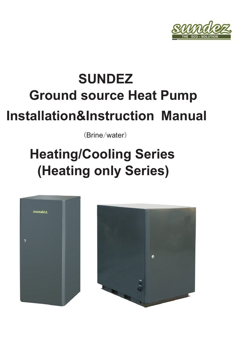
Sundez SDDC-050-B Service manual

DC INVERTER AIR TO WATER SPLIT HEAT PUMP
INSTALLATION & INSTRUCTION
MANUAL
R410A
Verson: 2013.01
Eco-friendly
DC inverter technology
Energy-saving
Safe

CONTENT
1. Warning.......................................................................................................01
2. Safety Information
3. Features
4. Model Number Nomenclature
5. Specification
6. Sturcture and Dimension
7. Installation
7.1 Installation Diagram
7.2 Installation of Outdoor Unit
7.3 Installation of Indoor Unit
7.4 Installation of Water Tank
7.5 Connect Indoor and Outdoor Unit
7.6 Installation of Water Pipeline
7.7 Installation of Power Source
8. Controller
8.1 User Interface
8.2 Button Function
8.3 Parameter Setting
8.4 Timer Function
8.5 Display Function
8.6 Error Codes
8.7 Memory Function
9. Maintenance
10. Trouble Shooting
......................................................................................01
...................................................................................................... 02
.................................................................... 03
...............................................................................................03
.............................................................................04
..................................................................................................05
..............................................................................05
.................................................................. 06
.....................................................................07
......................................................................09
..........................................................09
................................................................ 11
..................................................................12
....................................................................................................16
........................................................................................16
.....................................................................................17
..................................................................................18
.......................................................................................19
....................................................................................19
............................................................................................ 19
...................................................................................19
............................................................................................... 20
.......................................................................................21
DC Inverter Heat Pump

1.Warning:
2. Safety information:
O
Sundez DC inverter heat pumps are constructed according to the European technical standards
and safety regulations. The heat pumps are designed and built for heating or domestic hot water
production (DHW). In the event of improper use, dangers to the user or third parties may arise, as
well as damage to the heat pump and other objects. Any use not expressly indicated in this
manual is not permitted.
Safe keeping of the documentation
The installation manual should be issued to the end user of the heating system as part of the
handover and training process. It is then the responsibility of the user to keep the manuals safe
for future use by maintenance engineers.
Installation and maintenance carried out by professionist
The installation and maintenence of this heat pump must be carried out by a registered
professionist, who is suitably trained and qualified, including any stipulations laid down by law.
The appliance must be installed in such a way as to enable maintenance and/or repairs to be
carried out. The appliance warranty does not cover the costs for fork lift trucks, scaffolding, or
other elevation systems that may become necessary for carrying out servicing under warranty.
The warranty will be invalid if the advice given within the Installation instructions is not followed.
Use in compliance with the documentation.
This manual describes installation and service procedures for implementation by specialists. This
appliance is not intended for use by persons (including children) with reduced physical, sensory or
mental capabilities, or lack of experience and knowledge, unless they have been given supervision
or instruction concerning use of the appliance by a person responsible for their safety. Children
should be supervised to ensure that they do not play with the appliance. Rights to make any design
or technical modifications are reserved.
Please make sure the water flow is sufficient all the time.
All ground line connections must be prepared in accordance with relevant local regulations.
To reduce the risk of electrical insulation faults, you first make the connection of the protective
conductor of the heat pump safe according to local regulations.
When installation, make sure the inside wires are apart from hot or moving parts [ eg:
compressor, fan] of the system to avoid damage of the wires.
Anti-freezing measures must be well done to avoid damage to the water system and the heat
pump water heat exchanger.
It is very dangerous work done at the facility without previously cutting off the electricity from
the main power source.
When installing the system, please ensure that no contaminants enter the water cycle.
Additional current protection circuit breaker must be installed for electrical safety.
DC Inverter Heat Pump
01
•

Energy Saving and Environmental Friendly
With Advanced DC inverter technology, it can change the frequency and saves 40% energy than
normal heat pump in practical operation. The R410A refrigerant is friendly without pollution to the
environment.
Full Consideration for Noise Control
Compressor rubber feet are specially selected for reducing vibration. Specially, compressor is
located in the closed and isolated space inside the heat pump unit, without noise given out. Well-
balanced fans and fan motors, with the motors, with the optimized fan holder, contributes to the
low noiseoperation.The cabinet inside is insulated to reduce noise transmission.
DC Inverter Heat Pump Does Not Need Soft-starter
DC inverter heat pump technology not only saves energy, but also with soft starting feature. The
compressor motor is DC inverter type, and its starting is already soft-starting, so, no need to install
additional soft-starter, and its starting would not cause compact to your home power network.
Strong Cabinet
Standard unit fabrication consists of heavy gage galvanized sheet metal cabinet construction that
provides maximum strength. All interior sheet metal surfaces arepowder-painted for maximum
corrosion protection to ensure resilience for long term vitality. Compact, stackable cabinets are
designed to minimize installation space.
Reliable Design and Strict Quality Control
Standard safety features for the refrigerant circuit include high-pressure switch and low-pressure
switch to detect loss of refrigerant, as well as deficient water flow. Equipment safety features
include water loop temperature monitoring, voltage protection, water coil freeze protection. All
safety features are tested and run at the factory to assure proper operation of all components and
safety switches. All components are carefully designed and selected for endurance, durability, and
carefree day-to-day operation. Each unit is fully tested in performance and safety before it is
exported.
Easy Installation
Sundez DC inverter heat pumps are designed for easy installation. The refrigerant R410A has
already stored in the outdoor unit when ex-factory. The refrigerant can be released to the indoor
unit and the connecting copper tubes after vacuuming the indoor unit and the copper tubes. The
communication between the indoor unit and outdoor unit is simple with the fast plug, offering
power for circulation pump and signal for sensors and control panel on the indoor unit.
Simple Maintenance and Service ability
Full access for maintenance or service is provided from the maintenance panel, for better flexibility
in confined space. Easy removal of the control box from the unit provides access to all refrigerant
components. The refrigerant circuit is easily tested and serviced through the use of high and low
pressure ports integral to the refrigerant circuit.
3. Features
DC Inverter Heat Pump
02

SD DC -050 -B
Manufacturer SD - Sundez Eco-energy Solution Co., Ltd.
DC -Direct-current inverter
050-2HP 075-3HP 125-5HP
4. Model Number Nomenclature
5. Specification
DC Inverter Heat Pump
03
A-vertical fan discharge B-horizontal fan discharge

6. Structure and Dimension
Indoor unit
Outdoor unit
SDDC-050-B&SDDC-075-B SDDC-125-B
Plate type Heat Exchanger
Wilo Circulation Pump
Refrigerant Outlet
Refrigerant Inlet
Water Inlet
Water Outlet
Aviation Plug
H
L
W
H
L
W
Model L (mm) W (mm) H (mm)
SDDC-050-B 830 310 710
SDDC-075-B 880 360 800
SDDC-125-B 930 390 1270
DC Inverter Heat Pump
04

A:
Outdoor unit
Indoor unit Water tank
City water
B:
Outdoor unit
Indoor unit Water tank
City water
Shower
Shower
>30L
Outdoor unit
Indoor unit Water tank
City water
Radiator
Shower
C:
Floor heating
Floor heating
Filter
Filter
shower / DHW only.
floor heating +DHW
>30L
AAV
AAV
AAV
APV
CV WP
MFV
MFV
APV
CV WP
Note:
AAV: Auto air exhaust valve APV: Auto pressure bypass valve
CV: Control valve WP: Water pump
MFV: Manifold valve
7. Installation
7.1 Installation Diagram
floor heating + radiator + DHW
DC Inverter Heat Pump
05

7.2 Installation of Outdoor Unit
X
Higher than snow depth
Heat pump should be installed on a solid level base that can take the weight, preferably a concrete
foundation. If concrete slabs are used they must rest on asphalt or shingle.
The concrete foundation or slabs must be positioned so that the lower edge of the evaporator is at
the level of the local snow depth.
Heat pump should not be positioned next to sensitive walls, for example, next to a bedroom.
Also ensure that the placement does not inconvenience the neighbors.
Heat pump must not be placed so that recirculation of the outdoor air can occur; this causes lower
output and impaired efficiency.
Large amounts of condensation water as well as melt water from defrosting can be produced.
Condensation water must be led off to a drain or similar.
The outdoor unit should be installed in a ventilated place, with enough space for air inlet and
outlet, while without thermal radiation or other heat source. Besides, the air outlet should not
be against the wind.
Generally, horizontal air flow type heat pump does not need
sheltering. The structure design has protected all internal
components against rain and sunshine. A shelter is necessary to
avoid snow burying onto the heat pump in heavily snowy area.
Please make sure the standardized voltage 220V is stably
accessible to the heat pump, otherwise the performance would be
influenced.
The foundation of the heat pump can be cement or steel structure.
Anti-vibration rubber and a flat foundation should be taken into
account. The foundation structure can be flexibly designed
according to the working weight of the heat pump (Please see the
technical data in this manual).
DC Inverter Heat Pump
06

500 mm
Free space behind
500 mm 500 mm
3000 mm
Free space in front
500 mm 500 mm
1000 mm
Horizontal View
Vertical View
7.3 Installation of Indoor Unit
The position of indoor unit should be higher(Max. height difference 3 meters) or keep the same
level with outdoor unit.
X
Installation in balcony or on roof-top must be accordance with the allowable stress of the building
structure.
The unit location should avoid typhoon and earthquake damage.
The heat pump should not be installed in the air in case of crash accident. The installation place
should be with good ventilation condition. (The inlet and outlet of the air blower are illustrated in
the following diagram).
The installation space should be referred as follows:
Water drainage should be available near the installation location for draining water in an effective
way.
Do not install the heat pump in a place where there is polluting or corrosive material like oil,
flammable and explosive gas and sulfide etc. Keep it far away from sands, falling leaves and area
with high-frequency equipment.
DC Inverter Heat Pump
07

Intake and outlet should not be obstructed.
The wall the unit is to be mounted on should be strong enough to bear the weight and vibration of
the unit.
Allow for proper clearances around the unit.
Location should allow easy access for maintenance and removal of air filter.
Position unit and remote control at least 3 feet from electric appliances such as television, radios,
washing machine, etc.
To keep the lifetime of compressor, the maximum installation distance of outdoor and indoor unit is
5 meters, do not allow to longer than 10 meters. Additional refrigerant is required to fill up which is
according to the actual situation.
260 mm
200 mm
Expansion Bolt x 2
Hanging bracket x1
Installation:
1. Position the indoor unit at right height;
2.Drill two hole for the expansion bolt;
3.Insert the expansion bolt to the hole;
4. Install the hanging bracket with expansion bolt screw;
5. Hang the indoor unit with the pre-opening hole at the cabinet.
Bracket Hanging
hole
How to Install the Indoor Unit onto the Wall
DC Inverter Heat Pump
08

7.4 Installation of Water Tank
The water tank should be placed in a place where ambient temperature higher than 0 DegC.
It can be installed either in basement or on balcony (Some elements such as the size of water tank
and bearing capability of the building should be considered). Installation on bacony should be
based on support such as crossbeam or pillar.
The foundation of the water tank should be concrete such as crossbeam or pillar.
The water tank and the heat pump indoor unit should be at the same level, to reduce water pump
head and ensure enough water flow volume of the circulation pump inside the heat pump indoor
unit.
Do not install the water tank in a pollutive or corrosive area.
7.5. Connect the indoor and outdoor unit
7.5.1 Refrigerant piping insulation and protection
Fig. Enswathing two refrigerant copper pipes
Wiring Tape
Liquid pipe Gas pipe
Insulation
As below picture shown, it must take the insulation treatment for the refrigerant pipes and could
use the 15mm thickness PVC.
• Pack the two refrigerant copper pipes by insulation material separately in order to organize the
pipes easily by enswathing two pipes together, and should not be forced tied too closely to prevent
the frost caused by cold air.
The electricity cable can not contact with the refrigerant copper pipes.•
• Arrange the refrigerant copper pipes between indoor and outdoor unit, and make sure they are
well protected if they are buried in the ground.
7.5.2 Connect the indoor and outdoor unit
(1) The specification of copper pipes as follows;
Copper pipe Spec. Length
Refrigerant Inlet φ15.88 mm 5 meters
Refrigerant Outlet φ9.52mm 5 meters
(2) Refrigerant pipes length and height
The length of copper pipe between the unit and the heat pump should be less than 5 meters, and the
height difference should less than 3 meters.
DC Inverter Heat Pump
09

(3) Connect the pipes to the outdoor unit
a. Tank off the nut from the heat pump, expending the pipe and connect it to the heat pump;
b. Connect the pipe expending to the joints of the heat pump,then screw the nut, the torque please refer
to the picture;
c. Screw on the nut step by step according to the torque as shown.
Fig. The torque
refrigerant pipe
connection(big pipe)
refrigerant pipe
connection(small pipe)
7.5.3 Leakage check
7.5.4 Vacuum the the indoor unit
1). Unscrew the screw cap of the refrigerant inlet on the heat pump, and connect the multiplex
manometer to the check valve.
2). Connect the vacuum pump to the multiplex manometer, then switch to vacuum the indoor unit
and the connecting pipes. Make sure the absolute pressure is less than 70Pa.
3). After finishing vacuuming, take off the multiplex manometer and screw the cap, then open the
refrigerant inlet and outlet to release refrigerant from the outdoor unit to the whole system, until
the pressure is balanced. Finally please check the joints with suds.
It is necessary to perform leakage check after finishing the refrigerant copper pipes connection.
Inject nitrogen to the connecting copper pipes and the indoor unit up to 3MPa, and then check the
joints by suds or leakage hunter.
The refrigerant has been charged into the outdoor unit when ex-factory. Please vacuum the
connecting pipes and the indoor unit.
Indoor Unit
Heat Pump
Outdoor Unit
Low pressure
manometer
High pressure
manometer
Multiplex
manometer
Soft connection pipe
Vacuum pump
Fig. Vacuum the indoor refrigerant system
Refrigerant outlet Refrigerant inlet
DC Inverter Heat Pump
10

7.5.5 Connect communication plug
aviation
plug
aviation connector
View of the bottom of indoor unit
1 pair of aviation plug is used for the communication between indoor unit and outdoor unit, as well
as the power for indoor unit.
•
•
•
7.6 Installation of water pipeline
Indoor Unit
water inlet
refrigerant inlet
refrigerant outlet
water outlet
•
•
•
•
Drainage and flow pipe should be installed near the gutter or the sinkhole for efficient
condensed water draiange. Discharge valve is necessary on the drainage pipe.
Service valve needs to be installd before the magnet-valves on the system pipeline for further
inspection.
Telescopic issue of the pipeline between heat pump unit and water tank should be considered if
plastic pipeline such as PPR and ABS.
In winter, heat preservation may beed to be carried out for the water supply valve and the stop
valve of the system (according to local ambient temperature) for avoiding icing of the water
supply pipe and the valves.
Keep the water pipes staight and the pipeline allocation reaonable. Reduce pipe turnings as
many as possible to reduce water pressure drop and water flow.
Prevent the pipeline and the connectors from water leakage.
The water pressure bearing capability of each part of the piping system should be tested after
installation is finished. Drainage should be done to create a clear interior system.
Measures of heat preservatioinfor the hot water pipeline need to be conducted after assuring no
water leakage.
•
DC Inverter Heat Pump
11

7.7 Installation of power source
Model Cross-section area
of power supply wire Rated current of air breaker
SDDC-050-B 2
2.5mm 20A
SDDC-075-B 2
4mm 32A
SDDC-125-B 2
6mm 40A
View of power source cover View of power source terminal
Unscrew the two screws
Ground line
Null line
Live line
Only qualified electricians must carry out the installation in accordance with these instruction.
Before any work, isolate the equipment from the power supply.
The heat pump must be able to be separated from the main power supply by an additional isolator,
which disconnects all poles with at least 3mm contact separation. For this purpose, use contactors,
main isolators, fuses and so on.
Below is the recommended specification of the power cables and air breaker for the DC inverter
heat pumps:
DC Inverter Heat Pump
12

Wiring Diagram
Model: SDDC-050-B & SDDC-075-B
DC Inverter Heat Pump
13
CN23 CN24
CN4
CN19 CN21 CN16
CN6
CN17
CN8
CN11
CN10
CN2
CN9
+
-
~
~
CN27
CN15
FAN
CAPACITOR
YEL
WHI
RED
ORG
4-WAY-VALVE
t℃
2
t℃
2
t℃
2
AMB.
PIPE
EXHT
P P
LP HP
NO
COM
K1
N
BRIDGE
RECTIFIER
S
CR
CN1
N
UVW
P
Outdoor unit wire diagram
To indoor
unit
CN13 CN31 CN14
BLK
BLU Y/G
L
N
S
Y/G
L N S1 S2
RED WHIBLU
P6 P3
P4
P2
P5
P1
N-out
P-out
N-in
P-in
CN1
BLK
RED WHI
Power supply
Y/G
EV
TRANSFORMER
CN2
CN1
CN4
CN11
t℃
2
CN7
CN16CN12CN10
CN9
CN17
t℃
2
t℃
2
Inlet water
Outlet water
CN8
M
C
4
Display
Board
NO.
COM
To outdoor unit
L N S
Indoor unit wire diagram
RED BLU WHI
RED BLU

Wiring Diagram
DC Inverter Heat Pump
14
Model: SDDC-125-B
Outdoor unit wire diagram

DC Inverter Heat Pump
Model: SDDC-125-B
Indoor unit wire diagram
TRANSFORMER
CN2
CN1
CN4
CN11
t℃
2
CN7
CN16CN12CN10
CN9
CN17
t℃
2
t℃
2
Inlet water
Outlet water
CN8
M
C
4
Display
Board
NO.
COM
To outdoor unit
L N S
RED BLU WHI
RED BLU
15

8. Controller
8.1 User Interface
MODE
SET
CLOCK
ON
COMP
TIMER ON
TIMER OFF
AUX H.O.
COOL HEAT
UP DOWN
ON/OFF
Display area
Button operation
area
Explanation on the display area:
Lamp Explanation
ON This LED is on when the heat pump is power on.
This LED is on when the heat pump is at timer-on.
This LED is on when the heat pump is at timer-off.
This LED is on when the compressor is running.
This LED is on when the auxiliary heater is on.
This LED is on when the heat pump is in cooling mode (when the
heat pump is made as heating/cooling type).
This LED is on when the heat pump is in heating only mode
(when the heat pump is made as heating only type as standard).
AUX
COOL
H.O.
HEAT
TIMER ON
TIMER OFF
COMP
This LED is on when the heat pump is in heating mode (when the
heat pump is made as heating/cooling type).
DC Inverter Heat Pump
16

8.2 Button Function
MODE:
ON/OFF:
CLOCK AND TIMER:
SET:
1). When the heat pump is made as heating only type, the heat pump enters heating mode after
turned on, and at the same time LED “H.O.” lights up;
2). When the heat pump is made as heating/cooling type, press “MODE” button to choose
heating mode or cooling mode, and at the same time LED “COOL” or “HEAT” lights up.
For turning on/off the heat pump.
1). Clock setting (Hours: Minutes)
Hold "CLOCK" button, Minute area gets flashing; Press "CLOCK" again, Hour area get flash; Press
"UP" or "DOWN" to adjust the clock value. Press "CLOCK" button once more to save the clock value.
Or, the controller auto-saves the setting value and quit without button operating over 10 seconds.
2). Timer setting
Press "CLOCK" button, it displays the latest set value of TIMER ON, LED of "TIMER ON" gets flashing
and Minute area gets flashing and now press “UP” or “DOWN” button to adjust Minute value;
Press “CLOCK” button again, Hour area gets flashing now press “UP” or “DOWN” button to
adjust Hour value; Press "CLOCK" button again to confirm the TIMER ON value. LED "TIMER ON"
lights up. (Note: Now it switches into the TURN OFF timer setting.), or, the controller auto-saves the
TIMER ON set value and quits without button operating over 5 seconds. LED “TIMER ON” is on.
After TIMER ON setting, press "CLOCK" button, displayed the latest value of TIMER OFF, LED of
"TIMER OFF" gets flashing and Minute area gets flashing and now press “UP” or “DOWN”
button to adjust Minute value; Press “CLOCK” button again, Hour area gets flashing now press
“UP” or “DOWN” button to adjust Hour value; Press “CLOCK” button again to confirm the
TIMER OFF value, now the LED of TIMER OFF is on. Or, the controller auto-saves the TIMER OFF set
value and quits without button operation over 5 seconds.
3). Cancel the Timer
After timer value setting, press ON/OFF button under the unlock state and the timer is canceled.
"SET" button should use with "UP" and "DOWN" to set parameters' values. Press "SET" button to
enter parameter setting state. Every time press “SET” button it switches from Parameter P1 to P9.
Press "SET" button one more time to quit setting. Or, the controller auto-saves the set value without
button operating over 10 seconds.
In the parameter setting state, hold "ON"/"OFF" button for 5 seconds, release the button until
hearing a beeping to quit setting.
DC Inverter Heat Pump
17

Up:for switching or value increase.
DOWN: for switching or value reduction.
8.3 Parameter Setting
Press"SET" to enter parameter value setting, use "UP" and "DOWN" to setting the parameter's value
for P1 to P( Controller A)/ P1 to e (Controller B). Hold "UP" and "DOWN" button at the same time,
after hearing a warning tone, all parameters return to the default setting, and starting the water
tank heating mode.
Parameter Explanation Notes
P1 Water temp. set value(heating only unit) Ranges 40~60DegC, default 55DegC
P2 No use
P3 Water temp. set value in heating mode(heating/cooling
unit)
Ranges 20DegC~P8, default 35DegC
P4 Water temp. for boosting auxiliary heater Ranges 30~60DegC, default 60DegC
P5 No use
P6 Min. water temp. diff. for compressor re-start (heating only
unit)
Ranges 3~15DegC, default 5DegC.
P7 Min. water temp. diff. for compressor re-
start(heating/cooling unit)
Ranges 3~15DegC, default 5DegC.
P8 Max. water temp. for heating/cooling unit Ranges 25~70DegC, default 45DegC.
P9 No use
PA Duration of no temperature rising since auxiliary heater
starts
Ranges 2~90min, default 30min.
Pb No use
PC Water temp. diff. between actual temp. and set value, for
starting dropping compressor frequency
Ranges 0~6DegC, default 2DegC.
F Ambient temperature at which the unit stops running. Ranges -25~-1DegC.
P Ambient temp. datum point for temperature compensation
function(heating only unit)
Ranges -10~10DegC, default 5DegC.
X enable/disable temperautre compensation function 0: disable 1: enable
C Water Temp. set value range in cooling mode
(heating/cooling unit)
Ranges 5~35DegC, default 10DegC.
d Defrost mode 0: auto 1: manual
s Evaporator coil temp. to enter defrost Ranges -15~2DegC
I Interval between defrosts Ranges 25~70Min
t Defrost Duration 2~20Min
e Evaporator coil temp. to quit defrost 8~20DegC
DC Inverter Heat Pump
18
This manual suits for next models
2
Table of contents
Other Sundez Heat Pump manuals
Popular Heat Pump manuals by other brands

STIEBEL ELTRON
STIEBEL ELTRON WPL 33 installation instructions

Econar
Econar GeoSource DualTEK GV Series Installation and operating instructions

enphase
enphase Dimplex SI 6TU Installation and configuration manual

innovair
innovair Elite EIN13H2V32 manual

Goodman
Goodman SSZ 16 SEER Technical manual

Guardian
Guardian PLATINUM Series Installation & operation manual

ESP
ESP Varimax 20 ASHP Installation and operation manual

Danfoss
Danfoss Optyma OP-SMLZ Series instructions

Heat Siphon
Heat Siphon D owner's manual

Sanyo
Sanyo THS3632 Submittal sheet

Solahart
Solahart ATMOS AIR 270 Operation & installation manual

Nordyne
Nordyne Q5RD Series User's manual & installation instructions