Features
Specifications
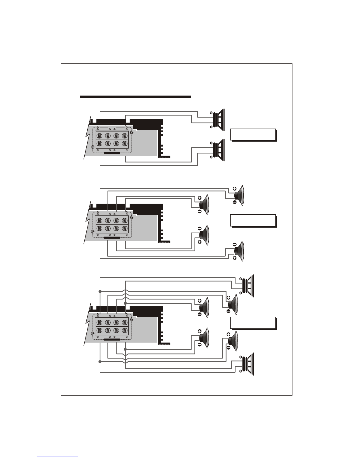
100W x 4CH
160W x 4CH
320W x 2CH
>100dB
30Hz~250Hz (CH1&2)
50Hz~5KHz (CH3&4)
50Hz~5KHz (CH1&2)
50Hz~1KHz (CH3&4)
10Hz to 100 Hz
0~18dB
35Hz to 120 Hz
10Hz ~ 40KHz (+/-1dB)
0.05%
75dB
>200
30A x 3
252(W) x 53(H) x 420(L)mm
Variable 200mV to 6V +/- 5%
DC 14.4V Negative Ground
Rated power output
-RMS Watt @ 4 Ohms -----------------------------
-RMS Watt @ 2 Ohms -----------------------------
-Bridged Power @ 4 Ohms -----------------------
Signal to Noise Ratio -----------------------------------
Low Pass Crossover -----------------------------------
------------------------------------
High Pass Crossover -----------------------------------
-----------------------------------
--------------------------------
Bass Boost -------------------------------------------------
--------
Frequency Response -----------------------------------
THD@RMS Watts ----------------------------------------
Channel Separation --------------------------------------
Damping Factor -------------------------------------------
Fuse Rating -------------------------------------------------
Dimensions -------------------------------------------------
Input Sensitivity -------------------------------------------
Power----------------------------------------------------------
Variable Subsonic Filter
Variable Bass-Boost Frequency Control
4/3/
MOSFET PWM Power Supply
Stable Into 4 Ohms Bridged or 2 Ohms Stereo Load
12dB Octave Electronic Crossover Slope
Variable Subsonic Filter
Independent 1/2 Channel High Pass Filter Variable
with x 10 Range Selectable Switch
Variable 1/2 Channel Low Pass Filter
with HPF/FULL/LPF Selectable Switch
Independent 3/4 Channel Low Pass Filter Variable
with x 10 Range Selectable Switch
Variable 3/4 Channel High Pass Filter
with HPF/FULL/LPF Selectable Switch
Independent 1/2 and 3/4 Channel Bass Boost Variable Control
Variable Bass-Boost Frequency Control
Variable Input Level Control
Signal Input and Line Out RCA Connectors
Multi-Way Protection circuitry
(Thermal/Over Current/Speaker Short/Speaker DC protection)
Tested Voltage & THD: 14.4V & Less than 0.05% THD
Operating Voltage : DC10V~16V Power Input
Wired Remote Control
2 Channel Bridgeable Class-AB Amplifier
-3-