1.The SunFounder 250 quadcopter is tailored for hobbyists and beginners for FPV flying.
2. This aircraft is light in structure with its propeller blades featuring high strength, explosive-resistant and small wind resistance due to their smooth
design.
3.It runs the firmware of CC3D flight controller, working with the SUNFOUNDER Simon 12A brushless motor and ESC.
4.Weight: 519g ; Duration of flight: 7 minutes;Working voltage: 11.1V
5. CC3D software debugging guide and the assembling videos of the aircraft are provided for you.
Components Test Before Assembly
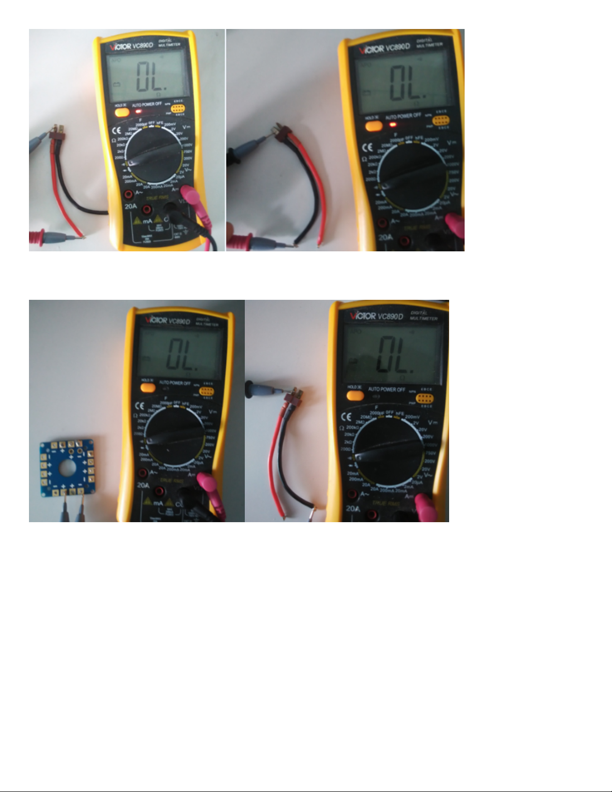
It’s necessary to test all the main components such as battery, motors, ESCs, flight controller board, etc., before assembly, in case of disassembling the
aircraft to test after assembly when you find it cannot work.
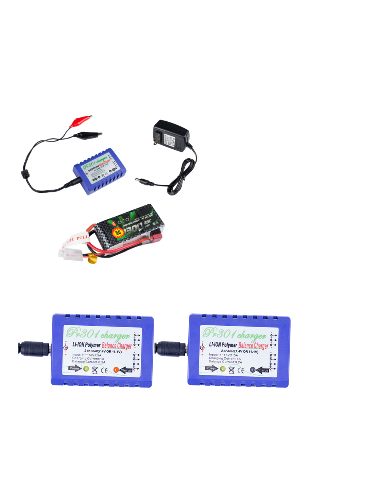
1. Battery, Balance Charger and Power Adapter Test
Test Operations:
1. Connect the PR301 Li-ion Polymer Balance Charger (Power Charger) and 12V 1.5A Power Adapter, and plug the adapter to a socket. The power
indicator on the balance charger will flash green, while the charging indicator orange (as shown in Figure 1-1). The charging indicator will dim one second
later (as shown in Figure 1-2), meaning the connection works fine.
Figure 1-1 & Figure 1-2
2. Connect the low-power 3S 11.1V 1300mAH T-Plug Li-Po Battery to the balance charger (DO NOT connect two or three batteries to charger at the same
time); Then the charging indicator lights up in red (Figure 1-3), indicating it’s charging.


