manuals.online logo
Brands
  1. Home
  2. •
  3. Brands
  4. •
  5. Sunlite
  6. •
  7. Outdoor Light
  8. •
  9. Sunlite 88144-SU User manual

Sunlite 88144-SU User manual

LED VAPOR TIGHT CEILING/WALL COMBO FIXTURE | 88144-SU
DIMMABLE
Compatible with most wall based 0-10V dimming controllers
WARNINGS & CAUTIONS: Risk of fire or electric shock, avoid fire or electric shock. Turn off the power at fuse or circuit breaker box before installation and maintenance to
avoid electric shock. Before installation thoroughly review encolsed installation manual. PROPER EARTH GROUNDING IS REQUIRED TO ENSURE SAFETY.Suitable for 120-277
Volt fused circuits,This product must be installed in accordance with the applicable installation code by a person familiar with the construction and operation of the
product and the hazards involved. If you do not have sufficient electrical wiring experience, please consult a qualified electrician. Consult a qualified electrician to ensure
correct branch circuit conductor. Do not make or alter any open holes in an enclosure of wiring or electrical components during installation. Please wear gloves to avoid
injury before installation. If the product is damaged, do not attempt installation and do not use. Not for emergency lighting. please use listed water proof strain relief
bushing when connecting the supply cord to the outlet box. Operating temperature -40°C - 50°C(-40°F - 122°F). Suitable for wet locations.
This device complies with part 15 of the FCC Rules. Operation is subject to the following two conditions: (1) this device may not cause harmful interence, and (2) this
device must accept any inteference received, including that may cause undesired operation.
1. Turn power OFF from the electrical panel before starting installation.
2. Carefully remove the fixture from the carton, and check that all parts are included, as shown in figure.
WIRING DIAGRAM & INSTRUCTION:
CCT SELECT AND DIMMING FUNCTION
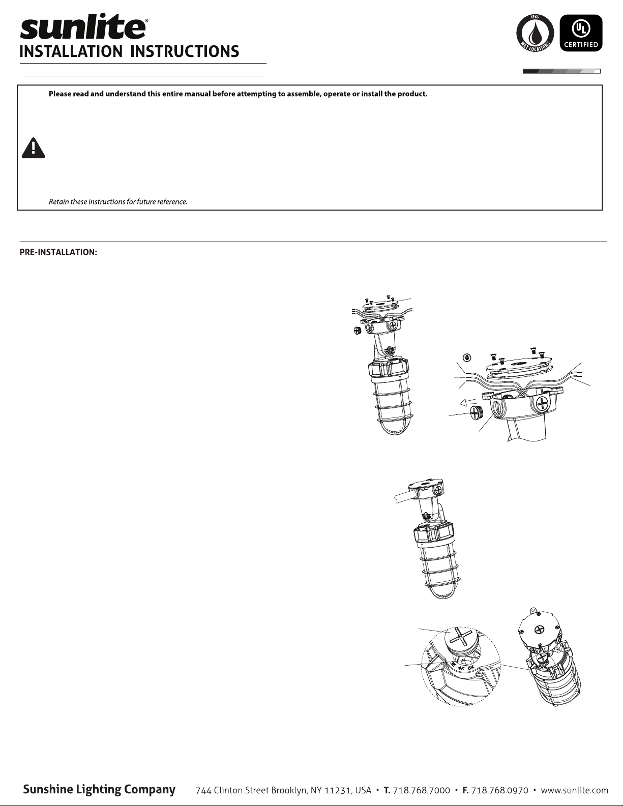
1. Unscrew the driver box cover, as shown in (Fig. 1)
2. Open the cover, there is a hanging rope at the lower left coner to prevent
falling off.
3. Unscrew the 1/2” NPT nut, install suitable conduit to the conduit opening,
pull the wire through the conduit hole and connect it to the terminal block
(Fig. 2) Wire connected to terminal block should be Aluminum or Copper
Conductors. See label at the terminal block for wiring.
4. Lock the driver box cover with screws. (Fig 3).
5. After installation, please ensure all the wiring is accordance with local
connection standard.
1. CCT and dimming function is optional for the fixture, and choose not to use
the function if it’s not required.
2. Wiring instruction for fixture with CCT function (Fig. 4).
a. Unscrew the gasketed cap from the fixture as shown in the images below.
b. adjust the CCT to descried setting.
c. Screw on gasketed cap.
3. Wiring instruction for fixture with dimming function.
a. Unscrew the driver box cover, as shown in (Fig. 1);
b. Wring according to purple and pink dimming as shown in (Fig.2)
Installation
Driver box cover
Figure 1
Figure 2
Figure 3
Green/Yellow Purple: Dim +
Pink: Dim -
Blue/White: ACN
Brown/Black ACL
Threading Hole
NPT Nut
Gasketed CAP
Selector Switch
Figure 4
NOTE: All the conduit openings must be closed by conduit or NPT nut, When ever installing the NPT nut or
conduit duiring installation or maintenance, please ensure silicone gel is added around the NPT nut.
1. Make marks on the wall and drill holes on the marks (Fig. 5), then
Use a hammer to put the expansion screws into the holes (Fig 6).
The holes on the bracket should be aligned with the expansion
screws (Fig 7).
2. Tighten the nut of the screws. (Fig 8).
3. Wiring according to the instructions on the first and second pages.
4. After installation, please wire in accordance with local wiring
standard and make sure to take good waterproof measures at the
joint of conduit. Users can adjust degree to left or right from
vertical downward direction by adjusting the screw on the bracket.
(Fig 9).
1. Use a chalk or sharp tool to mark signs on the top of the
ceiling then drill holes on the signs by electric drill (Fig
10).
2. Use a hammer to put the expansion screws into the holes
(Fig 11), the holes on the bracket should be aligned with
the expansion screws, then push the fixture to one sied
(Fig.11)
3. Tighten the nut of the screws. (Fig 12).Wiring according
to the instructions on the first and second pages.
4. After installation, please wire in accordance with local
wiring standard and make sure to take good waterproof
measures at the joint of conduit.
1. Unscrew the gasketed cap from the fixture (Fig 13).
2. Pass the wire in the threaded pipe through the hole and
connect to the wire of the terminal accordingly (Fig 14).
3. After the wiring is completed, put the threaded pipe into
the hole. Turn it clockwise to tighten it (Fig 14).
4. Lock the driver box cover with screws (Fig.15).
5. After installation, please wire in accordance with local
wiring standard and make sure to take good waterproof
measures at the joint of conduit.
CEILING MOUNT INSTALLATION
BRACKET WALL MOUNTING
THREADED PIPE MOUNTING
Figure 13 Figure 14 Figure 15
Gasketed CAP
Driver box cover
Pipe
112mm
10mm
Figure 5 Figure 6 Figure 7
Bracket
91
64
2-Ø10
Figure 10 Figure 11 Figure12
Figure 8 Figure 9

Other Sunlite Outdoor Light manuals

Sunlite 87994 -SU LFX-LBF-S-MW-SCT User manual

Sunlite

Sunlite 87994 -SU LFX-LBF-S-MW-SCT User manual

Sunlite 49148-SU User manual

Sunlite

Sunlite 49148-SU User manual

Popular Outdoor Light manuals by other brands

Gemmy 38262 Assembly instructions

Gemmy

Gemmy 38262 Assembly instructions

LSC Smart Connect 5426000150 quick start guide

LSC

LSC Smart Connect 5426000150 quick start guide

Nature Power Lifetime Series instruction manual

Nature Power

Nature Power Lifetime Series instruction manual

BGS technic 70051 instruction manual

BGS technic

BGS technic 70051 instruction manual

HOLOPHANE W Series Installation and maintenance manual

HOLOPHANE

HOLOPHANE W Series Installation and maintenance manual

LIGMAN BE-20051-LC installation manual

LIGMAN

LIGMAN BE-20051-LC installation manual

LIGMAN TA-31893 installation manual

LIGMAN

LIGMAN TA-31893 installation manual

Cree XSP Series installation instructions

Cree

Cree XSP Series installation instructions

BEGA 70 238 Instructions for use

BEGA

BEGA 70 238 Instructions for use

ANSMANN IL 300R Operation manual

ANSMANN

ANSMANN IL 300R Operation manual

IMMAX 08496L quick start guide

IMMAX

IMMAX 08496L quick start guide

Ares Marco Assembly instructions

Ares

Ares Marco Assembly instructions

LIGMAN PW49-GP153 installation manual

LIGMAN

LIGMAN PW49-GP153 installation manual

Quoizel SNNL8409K installation guide

Quoizel

Quoizel SNNL8409K installation guide

Monzana DBBL002 instructions

Monzana

Monzana DBBL002 instructions

LIGMAN FOR-10152 installation manual

LIGMAN

LIGMAN FOR-10152 installation manual

HOFFLIGHTS BULGARIA installation manual

HOFFLIGHTS

HOFFLIGHTS BULGARIA installation manual

LIGMAN ABA-20002-LC installation manual

LIGMAN

LIGMAN ABA-20002-LC installation manual

manuals.online logo
manuals.online logoBrands
  • About & Mission
  • Contact us
  • Privacy Policy
  • Terms and Conditions

Copyright 2025 Manuals.Online. All Rights Reserved.