Sunn Fun ROUND POOL User manual

ROUND
POOL
ASSEMBLY
INSTRUCTIONS
Part# 420363-16
Phone: (732) 574-1500 • Fax: (732) 574-1551
DANGER
DO NOT DIVE OR JUMP
into your pool. Your pool is
approximately 4' deep. It is
not designed for diving
or jumping. If you dive or jump
into your pool you run the risk
of permanent injury or death.
Alert all visitors
and family of
this and point
out all warning
labels supplied.
ADULT SUPERVISION REQUIRED
GENERAL
Installation of this above ground pool is not extremely hard
or confusing, but it is a big job. The secret to installing a
pool so that it will give you years of pleasure is to take the
time to follow instructions and do things right the first time.
Your pool warranty is void if these instructions are not
followed 100%. Read all instructions including accessories
such as filters, pumps, skimmers, decks, etc. prior to
starting. Before you start, check to see that you have the
correct number of parts. Use your parts list which is broken
down by carton. The manufacturer reserves the right to
revise, change, or modify construction of its pools.
NOTE: If a power drill is used during installation,
it should be a variable speed drill used on low
setting. Torque should not exceed 39 inch pounds.
FAILURE TO COMPLY COULD RESULT IN SCREWS STRIPPING OUT.
Sunn Fun
Pools

CONTRACT INSTALLATIONS
The manufacturer is in no way affiliated with any professional pool installer. Therefore the manufacturer can assume no
responsibility for errors in installation by the home owner or said professional installer. If you have your POOL installed
by others, please supervise them to be sure they comply with the proper installation techniques shown. Their past expe-
rience or short cuts may not cover the latest improvements in our POOLS. Do not allow any short cuts of any nature.
LOCAL CODES
• Local building code may require obtaining a building permit and or an electrical permit. The installer shall follow the
regulations on set backs, barriers, devices and other conditions.
• Any after market or home built deck should be built to the local building code requirements, including load capacity and
fencing requirements.
• All electrical outlet connections should be a minimum of 5 feet from the outside perimeter of the wall of the pool. From
5-10 feet there should be either a fixed connection (outlet box) or twist lock connection with a GFCI. Connect power
cords to a 3-wire grounding-type outlet only.
• Severe electrical shock could result if you install your pump or filter on a deck. They could fall into the water, causing
severe shock or electrocution. Do not install on a deck or other surface at, above or slightly below the top ledge of the pool.
BARRIER REQUIREMENTS
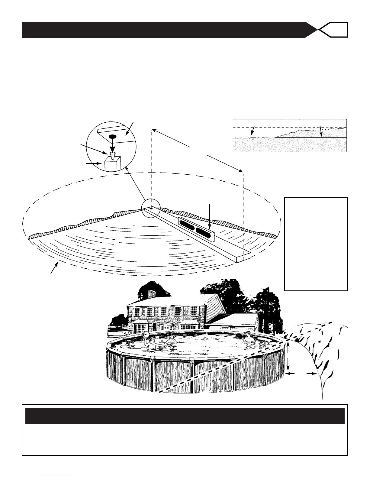
• If the distance from the top of the assembled pool is less than 48" vertically from the surrounding grade, a fence or
barrier is needed to surround the pool with a minimum height of 48".
• A barrier is necessary to provide protection against potential drowning and near drowning and is not a substitute for
constant supervision of children. A barrier is a fence, wall, or a combination thereof which completely surrounds the
swimming pool and obstructs access to the swimming pool. Barriers must comply with local and national building codes
and the US Consumer Product Safety Commission.
• These are minimum fencing and barrier requirements. Check your local building codes for other requirements they
may request. Optional fencing kits are available, Please contact your local dealer.
• If pool covers are used for safety barriers they should comply with ASTM F 1346 "Standard Performance Specification
for Safety Covers and Labeling Requirements for All Covers for Swimming Pools, Spas and Hot Tubs."
SPECIAL CARE
Even though this manufacturer's pools are designed to meet or exceed industry recommended safety factors, special
attention must be paid to some installation procedures that the installer performs and controls.
••
Levelness Spend the time to assure that the entire pool framework is level within 1". Unlevel pools place
extreme pressures on the pool walls.
••
Wall seam This area is where the wall joins together. Damage to any part of this area reduces the safety factors
and can result in a weak pool. Use extreme care following instructions.
••
Earth mound This keeps the liner from creeping out from under the pool wall. Follow instructions to the letter
– don't short-cut or substitute materials. Improperly installed pools can rupture, allowing thousands
of gallons of water to rush out causing extensive property damage and injury to anyone in its path.
• This manufacturers pools are not designed to be buried. Outside ground forces can collapse pool wall. Certain
conditions may exist, like the levelness of the pool area that require the pool to be recessed. You must maintain a
finished pool height of 36” above ground level. If your pool is 48” deep, you may recess the pool by 12” (48”-36”=12”).
Consult your local pool professional and building codes as to the use of earth retaining walls to recess your pool deeper
than this recommended amount. Make sure that the pool remains full of water for at least 7 days before backfilling the
pool recess. Place a layer of plastic film against the pool before backfilling to protect the pool from corrosion agents that
may be found in the backfill materials.
• The pool owner has the sole responsibility for providing adequate lighting for the pool area.
• All users must be able to see the shallow depth of the pool, and safety signs at all times.
• You must install a pool ladder(s) and/or steps for entry and exit from the pool.
• The use of artificial pool lighting is at the discretion of the pool owner.
• All electrical components shall be installed in accordance with Article 680 of the National Electrical code 1999 (NEC®)
“Swimming Pools, Fountains and Similar Installations” or its latest approved edition.
2

3
SOME FRIENDS
TO HELP OUT
Hammer
Knife
Tape
Rake
4” Nail
Pliers
Cloth Tape
Center
Stake
2 x 4
Sifted Earth
or Pre
Washed
Sand
Broom
Patio Blocks
Carpenters
Level
Shovel
Screwdriver
Hoe
INTRODUCTION
The installation of an average size pool (12' - 30' diameter) will usually require three
people to help set it up. Listed is an assortment of tools and materials which you will
need for preparing the ground, checking the levelness, and setting up the pool.
SELECTING POOL LOCATION
The selection and preparation of the pool site is your responsibility. The manufacturer
can only suggest the proper techniques, indicate the important considerations and
emphasize the precautions, and cannot be held responsible for damages to your pool
that may result from failure to carefully follow all pool site specifications.
1. The surface on which your pool will stand must be ABSOLUTELY LEVEL AND
SOLID. This condition should extend one (1) foot beyond the actual pool area all
around. The best surface is bare solid earth free from stones, roots, and other
sharp objects.
2. Allow plenty of play area around the pool. Fit the location into your
landscaping plans.
3. The pool site must be accessible to electrical and water supply and should allow
for disposal of great quantities of water when pool is drained.
4. When installing your pool on a SOLID LEVEL SURFACE, it is imperative that you
protect your pool and liner from chemicals and other foreign
matter contained in the surface. Protect your pool and liner by inserting between
them and the surface any material that is not made from a tar derivative or con-
tains sharp twigs, etc. We suggest the use of a plastic ground shield to be used
between the surface and the pool liner (See
step 2). Do not install your pool on peat moss, tar paper, gravel or
chemically treated soil not approved for pool use. Any or all of these
surfaces can ruin your pool and liner and will void your warranty.
5. Do not set up your pool under trees or under overhead wires.
6. DO NOT set up your pool near any existing structure such as your house garage,
etc., as this condition will induce diving or jumping into your pool which could
result in permanent injury or death.
7. Do not set up your pool on or near any septic system or underground utilities.
8. Choose your pool location convenient for:
a. Connecting electrical wires of your accessories (filter, heater, lights) to
your electrical outlets conforming to electrical codes.
b. Draining large amounts of water.
• During night time pool use, artificial lighting shall be used to illuminate all safety
signs, ladders, steps, deck surfaces and walks.
• The installer shall follow written instructions provided for operation of the circulation
system.
• Decks shell meet local codes and comply with ANSI/NSPI-8 1996 “Model Barrier
Code for Residential Swimming Pools, Spas and Hot Tubs” or the latest approved
edition.
• Underwater lights having front access shall be installed and removed only with use
of tools.
• The installer of the vinyl liner shall affix on the original or replacement liner, or on the
pool structure, all safety signs in accordance with the manufacturer’s instructions.
The safety signs shall be placed above the water line.
All components such as the filtration system, pumps and heater shall be
positioned so as to prevent their being used as a means of access to the
pool by young children.

4
INSTALLATION • ASSEMBLY STEPS
READ CAREFULLY BEFORE STARTING POOL ASSEMBLY
CONSTRUCTION CLOSE-UPS
Use the illustrations below as a guide for the assembly of your pool
Fig. A Fig. B
6”
DELMAR
ELAN • OMNI
LEXINGTON
POOLS
6”
PRINCETON
QUANTUM
ZENITH • ST. CROIX
POOLS
OPTIONAL
Fig. C
DELUXE POOLS
with Box Vertical

5
INSTALLATION • ASSEMBLY STEPS
READ CAREFULLY BEFORE STARTING POOL ASSEMBLY
CONSTRUCTION CLOSE-UPS
Use the illustrations below as a guide for the assembly of your pool
Fig. D Fig. F
6” EXTRUDED
ALUMINUM POOLS
with Box Vertical 9” POOLS
Fig. E
7” XL POOLS
with Column
Vertical

6
INSTALLATION • ASSEMBLY STEPS
READ CAREFULLY BEFORE STARTING POOL ASSEMBLY
CONSTRUCTION CLOSE-UPS
Use the illustrations below as a guide for the assembly of your pool
Fig. H
DELUXE POOLS
with Column Vertical
& Wrap Around Covers
Fig. I
SUPREME POOLS
with
Wrap Around Covers
Fig. G
7” XL POOLS
with Column Vertical
& Wrap Around Covers

Your pool must be installed on a solid level surface. Drive a stake into the ground at the center of
your pool location. Use a length of string tied to the center stake, see clearance chart for your size
pool, and mark the area using a can of spray paint or flour. With the use of the leveling device shown
and a shovel, start leveling the ground, removing all grass and sharp objects such as sticks and
stones.
Level area to the lowest spot within the clearance radius. DO NOT FILL IN LOW SPOTS. Give
special attention to the outer part of the circle as this is where the bottom track and pool wall will rest
and must be absolutely level.
7
PREPARING THE GROUND 1
CARPENTER’S LEVEL
DO NOT FILL IN DIG AWAY HERE
CLEARANCE RADIUS
CLEARANCE RADIUS
LEVEL AREA
WARNING - LEVELING THE GROUND
THIS IS THE MOST IMPORTANT PART OF YOUR PREPARATION OF POOL SITE.
YOU MUST GIVE CAREFUL ATTENTION TO THIS PHASE.
REMEMBER — YOUR POOL MUST BE INSTALLED ON SOLID LEVEL SURFACE.
CLEARANCE
RADIUS=1/2
POOL DIAMETER + 6"
12' Pool = 6' 6"
15' Pool = 8'
18' Pool = 9' 6"
21' Pool = 11'
24' Pool = 12' 6"
27' Pool = 14'
30’ Pool = 15’ 6”
The assembled pool
must have a vertical
distance of 3' from the
top of the pool to the
adjoining grade and
the adjoining grade
must remain level for
a distance of 4' away
from the pool. Refer to
the drawing at right.
PREVIOUS GRADE
3 FT.
4 FT.
CENTER STAKE
NAIL
2”x 4”

Remove wall from carton.
NOTE: the UP arrow on wall.
Determine starting point as the
filter inlet and outlet holes are at
the beginning of the wall. Starting
at the center of a bottom plate
insert the bottom edge of the
wall into the groove
on the bottom rail.
Ensure that the center line of the closure
holes in the the wall align with the center
of the plate. Make sure that the cutouts
for filter inlet and outlet are on the top por-
tion of the wall and will not be hidden behind
a vertical. If the wall ends do not meet, adjust
the bottom rail in or out of the bottom plates. The
spacing in all bottom plates should be equal.
8
BOTTOM RAILS 2
PRE WASHED SAND OR
SIFTED EARTH RECOMMENDED
REQUIREMENT CHART
12 ft. 1.4 Tons 1.1 Yards
15 ft. 1.9 Tons 1.5 Yards
18 ft. 2.6 Tons 2.1 Yards
21 ft. 3.4 Tons 2.7 Yards
24 ft. 4.4 Tons 3.5 Yards
27 ft. 5.4 Tons 4.3 Yards
30 ft. 6.5 Tons 5.2 Yards
BOTTOM RAIL
CENTER STAKE
BOTTOM RAIL
VERTICAL BOTTOM PLATE
BOTTOM PLATE
PATIO BLOCK 1/16”
OPTIONAL
GROUND SHIELD
Ground Shield and Wall Guard are optional.
Spread a ground shield or plastic sheeting over prepared ground
(not included). Ground Shield and Wall Guard are available from your
local pool supply dealer or polyethylene sheeting can be purchased
from a local hardware supply. This will protect your pool liner and
metal parts against chemical reactions from the ground soil.
INSERT WALL INTO BOTTOM RAILS 3
Mark out pool radius (1/2 pool diameter) using the center stake as reference. Form a circle by
sliding bottom rail groove up, into the bottom plates 1/16" from the stop.
To prevent stones or other foreign material from damaging the liner it is recomended to build
a 2” to 3” base of sand inside the entire pool.
Bring the required amount of clean and washed masonry sand into the pool area at this time. Refer
to chart above for the required amount. Place the patio blocks under each bottom plate at ground
level.
Check the levelness from the center stake to each bottom plate.
4’ x 4’ Plywood
SKIMMER INLET
SKIMMER OUTLET

9
CLOSING THE WALL 4
Insert the 1/4" - 20x3/4" truss head
screws from inside the pool through the
preattached inside closure bar, through
inside and outside wall ends, and through
outside closure bar.
The 1/4" serrated flange nuts are secured
to the screws on the outside of the wall. All
the holes must match and be secured
together with the screws and nuts provided.
Tighten each screw and nut to 85 inch
pounds of torque. If no torque wrench is
available, tighten each nut until snug. Then
tighten each nut one (1/2) half additional
turn. If nut appears to be lose after tighten-
ing, please check if the screw is stripped or
broken. It must be replaced.
Overtightening the nuts could cause the screws to fracture which could result in pool failure.
Failure to tighten the nuts sufficiently could also result in pool failure.
This is one of the most important structural assembly aspects you will perform.
Be absolutely sure you have assembled the wall as shown above for your pool.
Manufacturer can not assume the responsibility of the performance of this product if the
instructions of closing the wall are not followed exactly.
Pool Wall
4 CLOSURE
BARS
1/4" x 20 x 3/4"
TRUSS HEAD
SCREW
INSIDE
OF POOL
1/4" x 20
SERRATED
FLANGE NUT
A
DANGER
YOU MUST ASSEMBLE THE POOL WALL
AS PER INSTRUCTIONS
USE ALL THE 1/4"-20x3/4" TRUSS HEAD
SCREWS AND 1/4"-20 SERRATED FLANGE
NUTS TO CLOSE POOL WALL.
DO NOT LEAVE ANY OPEN HOLES
TIGHTEN EACH SCREW TO 85 INCH POUNDS.
B
During this assembly procedure,
make sure that one washer is on
the inside of the pool, and one
washer in on the outside of the
pool sandwiching the two wall
ends between them. Also ensure
that the recesses of the walls and
washers all face the same direction.
Align the holes in the wall ends.
From the inside of the pool, insert a 3/8 Truss Head screw
through the washer, through the holes on the inside and
outside wall ends, and through the second washer.
Fasten with 3/8 serrated flange nut on the outside of the
pool having the flange of the nut face the washer. Only hand
tighten the nuts at this point. Continue for each hole in the wall
ends.
DO NOT LEAVE ANY OPEN HOLES.
Tighten all screws and nuts to 85 inch pounds. If no torque
wrench is available, tighten each nut until snug. Then tighten
each nut one half (1/2) additional turn.
If nut appears to be lose after tightening, please check if the
screw is stripped or broken. If it is, it must be replaced.
DANGER
YOU MUST ASSEMBLE THE
POOL WALL
AS PER INSTRUCTIONS
USE ALL THE 3/8-16x3/4"
TRUSS HEAD SCREWS,
WASHERS AND 3/8-16
SERRATED FLANGE NUTS
TO CLOSE POOL WALL.
DO NOT LEAVE ANY
OPEN HOLES
TIGHTEN EACH SCREW
TO 85 INCH POUNDS.
View from
the top
3/8" TRUSS
HEAD SCREW
WASHER
WASHER
3/8 FLANGE
NUT
Pool Wall
Pool Wall
Recessed
Posi-Lock System

Wall guard is optional.
Tape wall guard (plastic sheeting) to pool wall 12" up from
ground and smooth out on ground 12" from wall. This will
protect your pools metal parts from chemical reactions with
the soil used in the earth mound.
Several commercial products can also be used in place of
earth mound. Consult your professional pool dealer.
10
RECHECKING YOUR WORK 6
EARTH MOUND 7
Using the center stake make sure your
pool is completely in true round by measuring
from the center of the stake to inside of pool
wall in all directions, making sure these
measurements are equal.
Remove center stake from pool area after
measurements and adjustments, if necessary,
are made.
POOL WALL
VIEWED FROM
ABOVE
RADIUS
CENTER STAKE
Build earth mound on top of wall guard using screened
damp earth or pre-washed sand. Shape and compact earth
mound to run 8" up from ground and 8" away from the wall.
Do not use any material that will compress under
pressure for the earth mound is an important part
of the pool installation. It prevents the wall from
lifting up and the liner from sneaking underneath
the pool wall. Spread the remaining sand equally
across the bottom of the pool. This will give you
a 2“ to 3” sand base.
Manufacturer cannot assume
responsibility of the performance
of this product if the earth mound
is omitted or not properly installed.
PROTECT YOUR LINER 5
CLOTH TAPE
OR DUCT TAPE
VIEW FROM
INSIDE OF POOL
WALL
SEAM
3 LAYERS
OF TAPE
SKIMMER
INLET FITTING
EARTH
MOUND
8”
8”
OPTIONAL
WALL
GUARD
12”
12”
DANGER
DO NOT USE ANY MATERIAL THAT
WILL COMPRESS UNDER PRESSURE
FOR THE EARTH MOUND.
SEE INSTRUCTIONS TO LEFT.
SKIMMER
RETURN FITTING
Once the wall is closed and screws and nuts are
tightened securely, cover the screw heads on the
inside of the pool with 3 layers of cloth tape all the
way from top to bottom of wall. If the filter inlet and
outlet are not used, cover over the pre-scored areas
on the inside of the pool wall with 1 layer of tape.
If your Pool Wall has the
Recessed Posi-Lock System an
additional layer of tape should be
added to the inside part of the
extended end of the wall.
Cloth tape or duct tape is
available through your local
pool dealer or hardware
store.
3 LAYERS
OF TAPE INSIDE OF
POOL VIEW
INSIDE OF
POOL VIEW
WALL
SEAM
EXTENDED
END OF WALL

11
THRU-THE-WALL SKIMMER 8
IMPORTANT!! BEFORE CONTINUING WITH THIS STEP
YOU MUST KNOW WHICH TYPE OF THROUGH THE WALL SKIMMER
YOU WILL BE USING WITH YOUR POOL
Your pool wall has cutouts to accomodate both standard size skimmers and deluxe wide mouth
skimmers. If you have a wide mouth skimmer, you will be required to remove the entire cutout as
shown in figure 1. To remove the section, you can use either tin snips or a hammer and knife as
shown in figure 3. If you have a standard size skimmer, only remove the inside section of the cutout,
and place duct tape around the remaining scored sections as shown in figure 2.
If the through wall filter inlet and outlet holes are to be used, remove metal cutouts by breaking
perforations using a knife and hammer as shown. Refer to skimmer manufacturer's instructions
for remainder of skimmer assembly. Make sure skimmer does not leak as this will corrode the
pool wall and cause a split in the wall that is not covered under the pool warranty.
It is recommended to coat the exposed metal on both sides with a clear lacquer or nail
polish to help resist rust and corrosion.
LARGE SKIMMER
CUT OUT ENTIRE AREA
SMALL SKIMMER
CUT INSIDE
AREA
ONLY
1
2
3
On inside of wall, tape over
holes and slots that will not be
used with duct tape or any
other cloth tape.

CAUTION
YOUR POOL IS DESIGNED TO PROVIDE AN AMPLE SAFETY MARGIN
WHEN IT STANDS ON LEVEL GROUND. FOR THIS PURPOSE A SLOPE
IN EXCESS OF 2 INCHES IN ANY DIRECTION WALL TO WALL IS
CONSIDERED OFF LEVEL YOUR POOL WARRANTY ONLY APPLIES TO
POOLS INSTALLED ON LEVEL GROUND AS DEFINED ABOVE.
ONCE YOU HAVE STARTED TO FILL THE POOL, DO NOT TRY TO PULL
THE LINER FORCEFULLY. THE WEIGHT OF EVEN ONE INCH OF WATER
WILL MAKE IT IMPOSSIBLE TO MOVE THE LINER WITHOUT DAMAGING IT.
12
LINER INSTALLATION 9
INCORRECT
CORRECT
POOL
LINER
AIR
SPACE
POOL
LINER
LINER
STANDARD OVERHANG LINER
1. Clear all sticks and sharp objects from an area near the pool, that is
as large as the pool itself. Remove the liner from its carton and unfold
and open the liner. Refold the liner so that it can easily be carried to
the pool and unfold from the outside of the pool. Check the
levelness of the sand in the pool and make sure that no sharp
objects are still in the pool.
2. Place the liner into the pool while holding onto the top of the
wall section of the liner. Overhang the top wall of the liner over
the pool wall approximately 4” and hold it by temporarily placing
the plastic edging over the liner and the wall. Continue in this
manner around the entire pool.
3. Gently pull on the liner and use a soft bristle broom to remove as many
wrinkles as possible on the bottom of the pool. Adjust the overhang of the
liner as needed as you go trying to keep it as equal as possible around the pool.
4. Be sure that the seam of the liner where the wall meets the floor of the liner is evenly centered in the pool.
Start filling the pool slowly with water. Continue pulling gently and working the liner with a broom, and
readjusting the overhang as necessary.
5. Some wrinkling of the liner may be evident and in no way affects the structural strength of your pool.
Once the water is filled to a point that the liner is pressed firmly against the wall install the
thru-the-wall skimmer following its instructions. Then you can fill the entire pool as quickly as
desired. The excess liner material overhanging the wall can either be trimmed later when the pool is
filled, or double folded now to the inside of the pool between the liner and the wall. Permanently install
the plastic edging around the entire pool, not leaving any gaps.
VINYL LINER
TOP RAIL
PLASTIC EDGING
OUTSIDE VIEW
OF POOL WALL
POOL
WALL
EARTH
MOUND

13
EZ HOOK LINER INSTALLATION
ATTENTION: An 8 inch cove must be placed all around the inside of the pool
1. Clear all sticks and sharp objects from an area near the pool,
that is as large as the pool itself. Remove the liner from its
carton and unfold and open the liner. Refold the liner so that
it can easily be carried to the pool and unfold from the outside
of the pool. Check the levelness of the sand in the pool and
make sure that no sharp objects are still in the pool.
2. Place the liner into the pool while holding onto the top of the
wall section of the liner.
3. Place the EZ Hook of the liner onto the top of the wall around the
entire pool. Temporarily place a few of the top rails over the liner
edging to support and sturdy the wall. Continue in this manner
around the entire pool.
4. Gently pull on the liner and use a soft bristle broom to remove
as many wrinkles as possible on the bottom of the pool.
5. Start filling the pool slowly with water. Continue pulling gently
and working the liner with a broom as needed.
6. Some wrinkling of the liner may be evident and in no way
affects the structural strength of your pool. Once the water
is filled to a point that the liner is pressed firmly against the
wall install the thru-the-wall skimmer following its instructions.
Then you can fill the entire pool as quickly as desired.
EZ HOOK
VINYL LINER
TOP RAIL
POOL WALL
OUTSIDE VIEW
OF POOL WALL
COVE
8”
8”
OPTIONAL
WALL
GUARD
12”
12”
BEADED LINER INSTALLATION
1. Clear all sticks and sharp objects from an area near the pool, that is as large
as the pool itself. Remove the liner from its carton and unfold and open the
liner. Refold the liner so that it can easily be carried to the pool and unfold
from the outside of the pool. Check the levelness of the sand in the pool
and make sure that no sharp objects are still in the pool.
2. Install the bead receiver onto the top of the pool wall. Temporarily place
a few of the top rails over the bead receiver to support and sturdy the wall.
3. Place the liner into the pool while holding onto the top of the wall section of
the liner.
4. Snap the bead of the liner into the bead receiver around the entire pool.
5. Gently pull on the liner and use a soft bristle broom to remove as many wrinkles as possible on the
bottom of the pool.
6. Start filling the pool slowly with water. Continue pulling gently and working the liner with a broom as
needed.
7. Some wrinkling of the liner may be evident and in no way affects the structural strength of your pool.
Once the water is filled to a point that the liner is pressed firmly against the wall install the thru-the-wall
skimmer following its instructions. Them you can fill the entire pool as quickly as desired.

14
VERTICALS, TOP PLATES AND RAILS 11
PRE-ASSEMBLY OF TOP PLATES* 10
No. 12 x 1/2”
Sheet Metal
Screw
If fencing or decking is to be installed, refer to the deck and fence instructions before installing
verticals. The holes indented in the face of the verticals must be on top.
If your pool is equipped with feature tape, it is best to apply it to the verticals at this time.
* NOTE: CAGE NUTS NOT NEEDED ON ALL POOLS - CHECK YOUR PACKING LIST
Before the top plates are installed it is necessary
to attach the cage nuts* in their appropriate
locations as shown in the figures at right.
Using a pliers, squeeze together the spring
sides of the cage
nuts and insert them
into the top
plate from
underneath.
CAGE NUT
TOP PLATE
PLIERS PLIERS
TOP PLATE CAGE NUT
TOP PLATE WITH CAGE NUT
1/4” CAGE NUT
Attention:
If your pool
has the 2 piece
resin vertical,
insert the flat
piece into the
vertical before
installation, as
shown.
VERTICAL

15
No. 12 x 1/2”
Sheet Metal
Screw
Insert two rails into a plate, in
the same manner and using the
same spacing as you have done
on the bottom rail and plate assembly. Push the rails
and plate assembly onto the plastic edging leaving the
far end in the air.
MAKE SURE THAT THE TOP PLATE IS CENTERED
DIRECTLY ON TOP OF THE BOTTOM PLATE.
Attach the vertical to the top and bottom plate using
the No.12x1/2" Sheet Metal Screws.
Insert the exposed end of a top rail into another
top plate with a top rail inserted into the opposite side.
Push the top plate with rails onto the edging again
leaving the far end of the rail in the air. Continue in
this manner all the way around the pool.
PLASTIC
EDGING
RAIL
TOP PLATE

16
INSTALLING LEDGES
AND PLACEMENT OF WARNING LABELS 12
No. 12 x 1/2”
Sheet Metal
Screw
Your pool is equipped with (3) three special warning ledges.
The (1) one ledge with a large warning on top is to be installed by the entry point
into the pool and is not to be obstructed by any object such as your ladder.
The (2) two ledges with the warning on the inside are to be placed opposite the
entry point into the pool with the warning facing the entry point.
THESE WARNINGS ARE NOT TO BE REMOVED
UNDER ANY CIRCUMSTANCES
NOTE: Your pools top ledge was not designed to be a walk around.
Caution everyone who uses your pool NOT TO WALK OR SIT ON THE LEDGE!
If your pool is equipped with feature tape it is best to apply it to the ledges at this time.
B
E
A
D
A
CBC
D
CDEEDC
E
BB
AA
Place ledges over the wall with each end
resting on a top plate. Using the above chart
as a guide align the set of holes in the top
plate as shown in the above drawing for your
size pool with the holes in the ledge and
insert the No.12x1/2" Sheet Metal Screw
through the ledge and into the top plate.
The actual screw holes that are used does
not affect the integrity of the pool. You may
use the set of holes that line up best!
The ledge screws should not be tightened
until all the ledges are in place and the
pool has been filled with water.
Attention: You must use the 5/16” x 3/4” OD Stainless
Steel Washers with each Sheet Metal Screw to secure the
top ledges to the top plates. Failure to use the washers
may result in damaged ledges.
Place ledges over the wall with each
end resting on a top plate. Align the
set of holes in the top plate as
shown in the instructions for your
size pool with the holes in the ledge
and insert the No.12x1/2" Sheet
Metal Screw through the washer
and the ledge and into the top plate.
INSTALLING LEDGES ON BAR HARBOR
& RIO VISTA MODEL POOLS ONLY
B
CC
D
E
DE
B
123
SCREW HOLE LOCATION GUIDE
12 ft. 15 ft. 18 ft. 21 ft. 24 ft. 27 ft. 30 ft.
ROUND ROUND ROUND ROUND ROUND ROUND ROUND
(4" Ledge/ 4" Vertical) B & D B & E B & E C & E C & E
(6" Ext. Ledge/ A & D A & D A & D A & D A & E A & D A & E
6" Old Extruded Vertical) A & E A & D A & E
FIG. A (6" Ledge/ 6" Vertical) E & C E & C E & C E & B E & B E & B E & B
FIG. B (6" Ledge/ 6" Vertical) E & C E & C E & C E & B E & B E & B E & B
FIG. C, D, E, G, H & I (
6” Ext. & 7" Ledge/ 6" Box Vertical) A & D A & D A & D A & E A & E A & E A & E
FIG. F (9" Ledge/ 8" Box Vertical) A & C A & C A & C A & D A & D A & D A & D
Refer to the "Construction Close-ups" at the
beginning of these Instructions as indicated below:
1
1
1
3
2
2

17
INSTALLING TOP COVERS 13
FOLLOW THE INSTRUCTIONS BELOW
FOR THE COVERS FOR YOUR PARTICULAR POOL
4", 6" & 7" DELUXE TOP COVERS
These covers don’t require cage nuts or top cover screws.
For pools with the new 1-piece deluxe top covers,
simply snap the cover into place, aligning the tab
on the bottom of the cover with the slot in the top
plate of pool (fig.A only.)
For 2-piece covers, insert bottom section into
top (fig. 1) so that it becomes one unit (fig. 2).
Then snap cover into place aligning tab on
bottom of cover with slot in the top plate of pool
(fig. 3) and secure with a #10 x 1" screw (fig. 4).
A
4
3
#10X1” SELF
TAPPING SCREW
IMPORTANT: Make sure that the inside edge of the top
cover is securely positioned over the edge of the ledges
2
1

18
6" & 7" TWO-PIECE FULL CONTOURED COVER
Slide inside cover (the cover which will be closest to the inside of the pool) into position and
place outside cover onto top of inside cover aligning the holes together with cage nut attached to
the top plate and secure using the 1/4”-20 x 3/4” screw provided. The two (2) edges of the covers
should be parallel. Before tightening the screws, press the two covers firmly together.
Line up the hole in bottom of cover with the hole in the vertical and fasten securely using the
No. 10 x 1” self tapping sheet metal screw provided.
INSIDE COVER
OUTSIDE FULL
CONTOURED COVER
OUTSIDE
FULL CONTOURED
COVER
1/4”-20 X 3/4”
STAINLESS STEEL SCREW
If your pool vertical does not have a hole, simply use the cover
as a template and drill through the vertical using a 9/64"
diameter drill bit, being careful not to damage the pool wall.
#10X1” SELF
TAPPING SCREW
1/4”-14x1” SELF
TAPPING SCREW
COVERS FOR 9" LEDGE POOLS NOTE: CAGE NUTS AND TOP COVER
SCREWS NOT NEEDED FOR THIS STYLE.
Using a #10 x 1"
sheet metal screw,
attach the bottom
cover to the
vertical using
the hole shown
at right.
TOP COVER
COVER BOTTOM
LEDGE
It is very
important
that the ledge be
fitted inside the
tab in the
bottom cover as
shown below.
Make sure that the
ledge remains in
this position.
CORRECT INCORRECT
LEDGE
LEDGE
COVER
BOTTOM COVER
BOTTOM
Hook the underside inside part of the top
cover under the ledge as shown. Then lower the
top cover until it rests evenly on the ledge. Place
a ¼"-14 x 1" self-tapping screw through the slot
in the bottom cover and screw into the hole in the
top cover. Be careful not to overtighten!

19
7" AND 9” TWO-PIECE WRAP AROUND COVER
AND PEDESTAL
Slide the inside cover (the cover which will be closest to the inside of the pool) into position
and align the hole in the cover with the cage nut attached to the top plate. Secure using the
1/4”-20 x 3/4” screw provided. Slide the outside cover onto the inside cover. Make sure the inside
cover is in the slot of the outside cover. Align the holes on the side of the bottom wrap with the
holes on the top of the vertical. Secure the cover using the #12 x 1/2” screws provided. The two
(2) edges of the covers should be parallel. Before tightening the screws, press the two covers
firmly together.
WRAP AROUND
PEDESTAL
Place the pedestal onto the
bottom of the vertical and align the
holes on the side of the wrap with
the holes on the bottom of the
vertical. Secure the pedestal using
the #12 x 1/2” screws provided.
INSIDE COVER
1/4”-20 X 3/4”
STAINLESS STEEL SCREW
#12X1/2” SCREW
1 ON EACH SIDE
#12X1/2” SCREW
1 ON EACH SIDE
If your pool vertical does not have holes, simply use
the cover or the pedestal as a template and drill through
the vertical using a 9/64" diameter drill bit, being careful
not to damage the pool wall.
9” WRAP
AROUND
COVER
7” WRAP
AROUND
COVER

7" XL TWO-PIECE WRAP AROUND COVER
AND PEDESTAL
1 - Insert the logo into the cover.
2 - Slide the outside cover into position and align the hole in the
cover with the cage nut attached to the top plate. Secure using
the 1/4”-20 x 3/4” screw provided.
3 - Insert the back of the top cover onto the back of ledges. and
securely snap the top cover into the hole in the front of the out
side cover.
4 - Align the holes on the side of the bottom wrap with the holes
on the top of the vertical. Secure the cover using the #12 x 1/2”
screws provided.
20
WRAP AROUND PEDESTAL
1 - Insert the logo into the pedestal.
2 - Place the pedestal onto the bottom of the vertical and align the holes on the side of the wrap
with the holes on the bottom of the vertical.
3 - Secure the pedestal using the #12 x 1/2” screws provided.
1/4”-20 X 3/4”
STAINLESS STEEL
SCREW
#12X1/2” SCREW
1 ON EACH SIDE
#12X1/2” SCREW
1 ON EACH SIDE
7” XL
WRAP
AROUND
COVER
OUTSIDE
COVER
TOP
COVER
1
2
3
4
1
23
LOGO
If your pool vertical does not have holes, simply use
the cover or the pedestal as a template and drill through
the vertical using a 9/64" diameter drill bit, being careful
not to damage the pool wall.
Table of contents
Other Sunn Fun Swimming Pool manuals
Popular Swimming Pool manuals by other brands

American Standard
American Standard 2732 installation instructions

Waterman
Waterman Waterfun 3000005CH Assembly and operating instructions

Intex
Intex EASY SET 128101NP owner's manual

Steinbach
Steinbach Speed Up instruction manual

Outside Living Industries
Outside Living Industries ubbink 410-H120 cm Note of assembly

Outside Living Industries
Outside Living Industries ubbink Ocea 355x550 - H120 cm Note of assembly