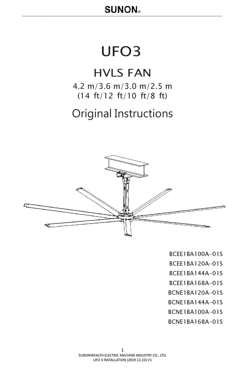
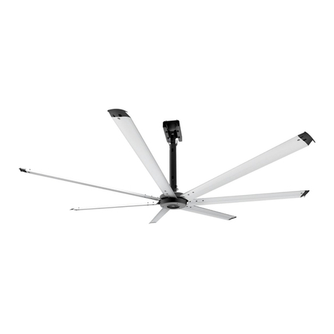
SUNON 3 Series User manual

POWERFUL HVLS FAN
SERIES 3
Installation Manual

C
WA
R
OB
S
1
2
3
4
5
6
7
8
9
1
1
1
1
1
1
POW
E
auti
o
R
NING - T
O
S
ERVE THE
F
.Installati
accorda
n
.Do not d
drilling i
n
.Use this
question
.Mountin
g
suspensi
suitably
q
.Do not o
and qual
.Before s
e
from bei
securely
.SUNON
p
responsi
mountin
g
complie
s
.While tu
r
fan to a
d
problem
s
examina
t
contact
c
.When s
e
disconn
e
remount
0. Do not
b
insert fo
r
1. This app
with red
u
knowled
g
the appli
2. SUNON
F
caused
b
3. If unusu
a
fan and
c
4. Powerful
disconn
e
turning
o
5. Please u
s
custome
E
RFULHVLSFAN
o
n &
S
O
REDUCE T
F
OLLOWING
on work a
n
n
ce with all
amage exis
n
to a wall
o
unit only
s, contact
t
g
of the s
u
on system
q
ualified p
e
perate any
f
ified techni
e
rvicing or
c
ng switche
d
fasten a pr
p
rovides in
bility of th
g
system,
t
s
with all fe
d
r
ning on po
w
d
amaged/d
s
by yours
e
t
ion and/o
c
ustomer s
e
e
rvice or r
e
e
ction of
a
ed as previ
o
b
end the ai
r
eign objec
t
liance can
b
u
ced physi
c
g
e if they
h
ance in a s
a
F
ans produ
c
b
y imprope
r
a
l oscillatin
c
ontact the
HVLS Fa
n
e
cting pow
e
o
n power t
o
s
e this unit
r service if
y
SERIES3Install
S
afet
H
E RISK OF
:
n
d electric
a
applicable
c
ting wiring
o
r ceiling.
in the ma
n
he manufa
c
u
spension
shall be pe
r
e
rsons.
f
an with a d
cian for ex
a
c
leaning un
i
d
on accide
o
minent w
a
stallation
g
e building
hat the bui
d
eral, state
,
w
er to the f
a
angerous p
e
lf. Please S
r repair. I
f
e
rvice.
e
placement
a
safety de
o
usly instal
r
foils when
t
s between
b
e used by
c
c
al, sensor
y
h
ave been
g
a
fe way an
d
c
t warranty
w
r
installatio
n
g moveme
n
manufactu
r
n
controlle
e
r, it still
r
o
the fan, it
only the
m
y
ou have q
u
ation Manual
t
y
ELECTRIC
S
a
l wiring m
codes and
s
and other
h
n
ner inten
d
c
turer.
system an
d
r
formed by
amaged co
r
a
mination
a
it, turn off
a
ntally. Whe
a
rning devi
c
g
uide for
m
owner an
d
i
lding struc
, and local
c
a
n, please
u
p
ower sourc
END the fa
n
f
there is
a
t
of a fan
e
vice, the
s
led.
installing,
rotating ai
r
c
hildren ag
e
y
or mental
g
iven super
v
d
understa
n
will not co
v
n
or use.
n
t is obser
v
r
er, its serv
i
r is equip
r
emembers
also keeps
m
anners sp
e
u
estions.
S
HOCK OR I
ust be do
n
s
tandards.
h
idden utili
t
d
ed by the
d
replace
m
the manuf
a
r
d or plug.
P
a
nd/or rep
a
a
ll the pow
e
n the circui
c
e, such as
m
ounting f
a
installer t
ture is sou
c
odes.
u
se it with c
e. DO NOT
n
back to a
u
a
ny questi
o
componen
s
afety devi
servicing,
o
r
foils.
e
d from 8 y
e
capabilitie
s
v
ision or in
d the haza
r
v
er equipm
e
v
ed, immed
i
i
ce agent, o
ped with
a
the previ
o
previous o
p
e
cified by t
h
NJURY TO
P
e by quali
f
t
ies/device
s
manufactu
ent of par
t
a
cturer, its
P
lease cont
a
a
ir.
e
r switches
t
t breaker c
a
a tag, to th
e
a
ns; howev
e
o ensure t
h
n
d and tha
t
a
ution. DO
a
ttempt to
u
thorized s
o
n with ins
t requires
c
e is to b
o
r cleaning
e
ars and a
b
s
or lack o
f
s
truction c
o
r
ds involve
d
e
nt damage
i
ately stop
u
r suitably q
a
memory
o
us operati
p
eration m
o
h
e compan
y
P
ERSONS,
f
ied perso
n
s
when cutt
i
u
rer. If you
r
ts of the
s
service age
a
ct manufa
c
t
o prevent
p
a
nnot be l
o
e service p
a
e
r, it is th
e
he safety
o
t
the instal
NOT conne
resolve ele
c
s
ervice cent
s
tallation,
p
the remo
v
b
e reinstall
e
the fan.
D
b
ove and pe
f
experienc
e
o
ncerning
u
d
.
or failure t
using the c
ualified pe
r
function.
i
on mode.
o
de.
y
. Please c
o
1
n
(s) in
i
ng or
have
s
afety
nt, or
c
turer
p
ower
o
cked,
a
nel.
e
sole
o
f the
lation
ct the
c
trical
er for
p
lease
v
al or
e
d or
o not
rsons
e
and
u
se of
hat is
eiling
r
sons.
After
Once
o
ntact

Th
Ple
a
ma
n
In
o
the
POW
E
ank you
a
se read thi
n
ual in safe
o
rder to pro
purchase
d
E
RFULHVLSFAN
for pur
c
s manual c
a
place.
tect your ri
g
d
ate, dealer
’
SERIES3Install
c
hasing
a
refully bef
o
g
hts and in
’
s name, et
c
ation Manual
SUNON
o
re use, us
e
terests, pl
e
c
. on the g
u
product
e
the produ
ase make
s
u
arantee.
s!
ct accordin
ure that th
e
gly and ke
e
e
deals rec
o
2
e
p the
o
rds

T
a
POW
E
a
ble
Page
4
5
6
7
7
Page
8
9
9
10
Page
11
Page
12
17
18
19
Page
20
20
21
22
23
E
RFULHVLSFAN
of C
o
Introduct
Fan Outli
Product
S
Installati
o
The Placem
The Placem
Pre-Insta
Inside th
e
Tools Re
q
Fan Diag
r
Pre-Insta
Installati
o
I-beam
Installing
Installati
o
Fan Con
n
Warning
Power Re
q
Recomme
n
Wiring Di
RF Remo
t
Informati
Troubles
h
General
T
Maintena
Powerful
Warranty
SERIES3Install
o
nte
n
ion
ne
S
pecificati
o
n Precau
t
ent & Clearan
c
ent & Clearan
c
llation
e
box
q
uired fo
r
r
am
llation C
h
o
n Overvi
e
the Fan
o
n Metho
d
n
ection
q
uirements
n
ded Wire Spe
c
agram
t
e Contro
l
on
h
ooting
T
roublesh
nce
HVLS Fan
ation Manual
n
ts
ons
tions
c
e between Fa
c
e between Fa
r
Installati
h
ecklist
e
w
d
cification
l
ooting
Series 3
n and Obstru
c
n and HVAC
D
on
Model Li
s
c
tions
D
iffuser
s
t
3

Int
r
Tha
styl
i
We
nea
F
a
8
1
0
1
2
1
4
POW
E
r
oduction
nks for cho
o
i
sh choice. I
t
assure you
t
r future.
a
n Ou
t
D
ft /2.5 m
0
ft /3.0 m
2
ft /3.6 m
4
ft /4.2 m
E
RFULHVLSFAN
o
sing our p
r
t
’s energy
-
t
his applian
t
line
A
1.1 ft
/350 m
m
SERIES3Install
r
oducts, Po
w
-
saving, eco
c
e will mak
e
B
m
0.6
5
/200
ation Manual
w
erful HVLS
-friendly d
e
e
your spac
e
5
ft
mm /
8
Fan is an ef
f
e
sign brings
e
cozier and
H1
2.8 ft
8
40 mm
f
icient, eco
n
excellent ai
r
occupant c
o
H2
3.3 ft
/1000 m
m
n
omical and
rflow to spa
o
mfort in t
h
H
3
m
0.11
/35
m
4
ce.
h
e
3
ft
m
m

Int
r
P
r
Po
w
Inp
u
2
Po
w
Inp
u
2
Po
w
Inp
u
2
Po
w
Inp
u
2
POW
E
r
oduction
r
oduc
t
w
erful HVLS
ut Voltage
(V
AC
)
00-240
w
erful HVLS
ut Voltage
(V
AC
)
00-240
w
erful HVLS
ut Voltage
(V
AC
)
00-240
w
erful HVLS
ut Voltage
(V
AC
)
00-240
E
RFULHVLSFAN
t
Spec
Fan Series
Input
Frequency
(Hz)
50/60
Fan Series
Input
Frequency
(Hz)
50/60
Fan Series
Input
Frequency
(Hz)
50/60
Fan Series
Input
Frequency
(Hz)
50/60
SERIES3Install
ificati
3-8 ft (2.5
Maxi
m
Rated P
(W
)
33
5
3-10 ft (3
m
Maxi
m
Rated P
(W
)
23
2
3-12 ft (3.
6
Maxi
m
Rated P
(W
)
17
6
3-14 ft (4.
2
Maxi
m
Rated P
(W
)
17
1
ation Manual
ons
m)
m
um
P
ower
)
M
Rat
e
5
m
)
m
um
P
ower
)
M
Rat
e
2
6
m)
m
um
P
ower
)
M
Rat
e
6
2
m)
m
um
P
ower
)
M
Rat
e
1
M
aximum
e
d Current
(A)
2.04
M
aximum
e
d Current
(A)
1.44
M
aximum
e
d Current
(A)
1.12
M
aximum
e
d Current
(A)
1.1
Maximum RP
M
(RPM)
150
Maximum RP
M
(RPM)
100
Maximum RP
M
(RPM)
70
Maximum RP
M
(RPM)
56
M Noi
s
(dB(
A
<4
0
M Noi
s
(dB(
A
<4
0
M Noi
s
(dB(
A
<4
0
M Noi
s
(dB(
A
<4
0
5
s
e
A
))
0
s
e
A
))
0
s
e
A
))
0
s
e
A
))
0

Int
r
I
n
1
2
3
4
5
6
7
8
9
1
1
1
1
1
1
1
1
1
1
2
POW
E
r
oduction
n
stall
a
.This HVL
S
platform
.Please s
w
shock or
.All wirin
g
the local
personn
e
.An earth
and the
p
.The pow
e
.The han
g
.Do not d
a
.To avoid
wire exp
o
.Do not b
e
0. The HVL
S
installati
o
property
1. Please e
n
before in
2. All fan p
a
must be
structure
3. The dist
a
and no o
b
4. The fan
m
5. Multiple
f
the fan d
6. The fan
s
HVAC eq
u
the fan a
n
7. If the fan
must be
a
is mount
e
2.5x the
8. Pleases
combusti
9. The fan
i
bigger th
of the H
V
2
0.
Proper s
y
occupant
E
RFULHVLSFAN
a
tion
P
S
fan need
a
and at leas
t
w
itch off all
t
lighting sh
o
g
constructi
o
electrical
e
l.
leakage cir
c
p
ower switc
h
e
r switch m
u
g
er must be
a
mage elect
fire or othe
r
o
sed outsid
e
e
nd the airf
o
S
fan model
o
n manual
a
damage.
n
sure that
t
stallation.
a
rts must b
e
free of ob
s
componen
t
a
nce should
b
structions
m
ust be inst
f
ans must
b
iameter.
s
hould not b
u
ipment. Ai
r
n
d outside
t
is mounte
d
a
t a distanc
e
e
d below an
measure of
see the m
bles.
i
nlet or oth
e
an 1 times t
V
LS fan.
y
stems orie
n
comfort. Pl
SERIES3Install
P
reca
u
a
proper de
v
t
two install
a
t
he power s
o
ck.
o
n must co
m
law, then
c
uit breaker
h
.
u
st be fitted
securely m
o
rical wiring
r
hazards,
m
e
the fan ap
p
o
ils when in
s
covered b
y
a
nd all natio
t
his applica
t
e
≥2 ft (0.
6
s
tructions s
u
t
s.
be at least
3
in this area.
a
lled so tha
t
b
e spaced at
e located n
e
r
supply out
l
he swept ar
at the sam
e
e
that is at l
e
HVAC diffu
s
the fan’s di
a
anufacturer
e
r return ai
he diameter
tation will
p
ease refer t
o
ation Manual
u
tions
v
ice which c
a
a
tion perso
n
upply befor
m
ply with th
e
must be i
n
(<30 mA) s
with a fuse
o
unted to th
and other h
m
ake sure th
a
p
earance or
stalling the
y
the install
a
nal/local el
e
t
ion is equi
6
m) from
a
uch as ligh
t
3
.3 ft (1 m)
f
t
it is at lea
s
t
a center-t
o
e
ar to air su
lets/inlets c
r
ea of the fa
n
e
level or hi
g
e
ast 1.5x th
e
s
er, the win
g
a
meter.
r
’s require
m
r point tha
t
r
of the ceili
n
p
rovide an e
n
o
the illustr
a
a
n support i
n
s.
e installatio
e
national el
n
stalled by
h
ould be in
s
(≥20 A).
e ceiling or
idden utiliti
e
a
t the wires
other parts
fan.
a
tion instru
c
e
ctrical cod
e
pped with
A
a
ll obstructi
o
t
s, cables,
s
f
rom the to
p
s
t 10 ft (3.0
5
o
-center dis
p
ply outlets
an be confi
g
n
.
g
her than a
n
e
measure o
f
g
lets must
b
m
ents for
t
t
produces
n
g fan. This
s
n
hancemen
t
a
tion below.
ts weight s
u
n to avoid t
h
ectrical cod
e
profession
a
s
talled betw
e
beam.
e
s/devices
w
are comple
t
.
c
tions must
e
s to avoid
p
A
C single
p
o
ns. The fa
n
s
prinklers,
o
p
of the win
g
5
m) above
t
tance that i
s
or exhausti
g
ured to deli
n
HVAC diff
u
f
the fan’s d
i
b
e at a dista
n
t
he minim
u
n
egative pr
e
s
ystem will
r
to the Indo
o
u
ch as aeria
l
he risk of e
l
e
s, standar
d
a
l technicia
e
en the app
w
hen install
a
t
ely inside,
n
comply wit
p
ersonal inj
u
p
hase 200-
2
n
installatio
n
o
r other bu
glet to the
c
t
he finished
s no less th
i
ng inlets of
i
ver air awa
y
u
ser, the wi
n
iameter. If t
h
n
ce that is a
t
u
m clearan
c
e
ssure sho
u
r
educe the
a
or Air Quali
t
6
l
work
l
ectric
d
s and
ns or
liance
a
tion.
n
o any
h this
u
ry or
2
40 V
n
area
ilding
c
eiling
floor.
an 3x
other
y
from
n
glets
h
e fan
t
least
c
e to
u
ld be
a
irflow
t
y and

Th
A-
B-
C-
D-
E-
Th
POW
E
e Place
m
The tip of
obstacles.
The Ceilin
g
The tip of
obstacles.
Spacing b
e
Space fro
m
e Place
m
The HVLS
The HVLS
E
RFULHVLSFAN
m
ent &
C
airfoil need
g
fan need
the airfoil
n
e
tween fan
s
m
wall at le
a
m
ent &
C
fan positio
fan positio
SERIES3Install
C
learanc
e
at least 2 f
t
at least 10
n
eed at lea
s
s
at least 3
x
a
st 1.5x di
a
C
learanc
e
n need to
a
n need to
b
ation Manual
e
betwe
e
f
t (0.6 m) a
w
ft (3.05 m)
s
t 3.3ft (1
m
x
diameter
o
a
meter awa
y
e
betwe
e
a
bove the H
V
b
elow the H
V
e
n Fan a
w
ay from lig
away from
m
) away fro
m
o
f the fans
a
y
from the
w
e
n Fan a
V
AC outlet
A
V
AC outlet
nd Obst
ht or any e
q
floor.
m
beam / c
e
a
part.
w
all.
nd HVA
C
A
: The dist
a
center of
and HVA
C
need to
a
diameter
.
B: The dist
a
the cent
e
fan and
H
need to
a
diamete
r
ruction
s
q
uipment a
e
iling and
n
C
Diffus
e
a
nce betwe
e
the ceiling
C
equipme
n
a
t least 1.5
x
.
a
nce betwe
e
r of the ce
H
VAC equi
p
at least 2.5
r
.
7
s
n
d no
n
o
e
r
e
n the
fan
n
t
x
en
iling
p
ment
x

Pre
In
Mai
E
Har
d
Fix
e
B
r
Guy
M
1
M
Air
f
POW
E
-Installat
side t
n Box
Yoke*1
xtension Tub
e
dware and
e
d Angle Mou
n
r
acket Shim*2
Wire Bracket
*
1
0 50L 4 Bolt
K
8 55L 3 Bolt
K
f
oil Box
E
RFULHVLSFAN
ion
he b
o
M
e
*1Exte
n
Bolt Kits
n
t I-bea
m
*
4
*
2 Turn Bu
K
itM1
0
K
itM6
SERIES3Install
o
x
Fixed Angle
M
ound Bracket
*
n
sion Tube Sh
i
m
Shim
4
I-
ckle*4 Be
0
35L 4 Bolt Ki
t
16L 4 Bolt Kit
ation Manual
*
1
i
eld*2
S
beam Clamp
*
am Clamp Set
t
M1
0
M6
Motor*1
S
afety Cable*1
*
2 Wi
n
*4 Ferr
i
Cl
a
0
70L 3 Bolt Ki
t
35L 7 Bolt Kit
R
e
Wi
r
n
glet*7
te Bead
a
mp*1
t
M
8
M
6
e
mote Contro
l
r
e Rope Clam
p
Extension
T
Clamp *
2
Earth Wir
e
8 15L 6 Bolt
K
6
35L 21 Bolt
K
Airfoils
8
*1
p
*20
T
ube
2
*1
it
K
it
*7

Pr
e
T
o
Me
F
a
POW
E
e
-Installat
o
ols
R
chanical I
Standard
w
Standard
A
Hydraulic
Galvanize
length ac
c
Torque w
r
inspectio
n
Electronic
a
n Di
a
E
RFULHVLSFAN
ion
R
equir
e
nstallatio
w
rench/so
c
A
llen wren
c
cutter
d wire Ø4
m
c
ording to
t
r
ench 50~3
n
purpose)
level
a
gram
SERIES3Install
e
d fo
r
n
c
ket set
c
h set
m
m (Trim t
h
t
he situatio
n
00 kgf.cm
(
ation Manual
r
Inst
a
E
h
e wire
n
)
(
For
a
llatio
n
lectrical I
n
Phillips
Flat he
a
Multim
e
Pair if
#
n
n
stallatio
n
screwdrive
r
a
d screwdri
v
e
ter
14 to #24
A
n
r
v
er
A
WG stripp
e
9
e
rs

Pre
P
r
POW
E
-Installat
r
e-Ins
t
Equi
p
The
dire
c
met
h
The
m
The
m
the f
a
Havi
n
For
t
met
e
betw
For
t
obje
c
(Plea
” Pa
g
The
c
the
d
betw
Whe
n
from
& Cl
e
The
y
(Plea
The
conv
e
For
p
The
a
E
RFULHVLSFAN
ion
t
allati
p
ped with
a
fan can o
n
c
tly to a sin
g
h
ods not in
c
m
ounting s
t
m
ounting s
a
n.
n
g been fa
m
t
he fan ins
t
e
rs) above
t
een Fan an
d
t
he fan in
s
c
ts/buildin
g
se refer to
“
g
e 7)
c
enter-to-
c
d
iameter o
f
een Fan an
d
n
installing
HVAC syst
e
e
arance bet
w
y
oke kit siz
se refer to
“
power sup
p
e
rter, and t
p
ower requi
a
irfoil shou
SERIES3Install
on C
h
a
ppropriate
n
ly be mou
g
le stringer
c
luded in th
t
ructure ap
ystem mus
t
m
iliar with t
t
allation, th
t
he ground
d
Obstructi
o
s
tallation,
g
structure
“
The Place
m
enter dista
n
f
the fans.
d
Obstructi
o
the fan, m
a
e
ms or larg
w
een Fan a
e
should m
“
I-beam” P
a
p
ly unit co
m
he wires p
a
rements, p
l
l
d not be
m
ation Manual
h
eckli
s
mounting
k
nted to th
e
r
, truss shel
is manual,
proved by
s
t be able t
o
he functio
n
h
e fan blad
e
. (Please r
e
ons ” Page
the distan
c
should be
a
m
ent & Clea
r
n
ce betwee
n
(Please re
f
ons ” Page
ake sure t
h
e garage d
o
nd HVAC D
atch the I-
b
a
ge 11)
m
plies wit
h
a
ss through
l
ease refer
t
m
ix up with
o
s
t
k
it for roof
e
I-beam.
f or light s
t
p
lease con
s
s
tructural e
n
o
withstand
n
s of the sa
f
e
s should
b
e
fer to “Th
e
7)
c
e betwee
n
a
t least 2 fe
r
ance betw
e
n
two
f
ans
s
f
er to “Th
e
7)
h
e fan is n
o
o
ors. (Pleas
e
iffuser ” Pa
g
b
eam.
h
the speci
f
the fan in
s
t
o voltage
s
o
ther airfoi
pitch.
DO NOT
m
t
eel shelf. F
s
ult a struct
n
gineers.
the torque
f
ety cable.。
b
e at least
e
Placemen
t
n
the blad
e
et (0.6 met
e
en Fan an
d
s
hould be a
t
Placemen
t
o
t affected
b
e
refer to “
T
g
e 7)
f
ication of
t
tallation p
o
s
ticker on t
h
l boxes.
m
ount the
f
or installat
i
ural engin
e
generated
。
10 feet (3
.
t & Cleara
n
es and ot
h
ers).
d
Obstructi
o
t least 3 ti
m
t
& Cleara
n
b
y high wi
n
T
he Placem
e
t
he freque
n
o
sition.
h
e fan.
10
f
an
i
on
e
er.
by
05
n
ce
h
er
o
ns
m
es
n
ce
n
ds
e
nt
n
cy

In
I-
Th
e
us
e
thi
c
14
-
th
e
bu
i
POW
E
stallation
beam
e
yoke to I
-
e
d within t
h
c
kness of 1
-
20 mm (t)
,
e
fabricated
i
lding is ap
p
E
RFULHVLSFAN
Overvie
w
-
beam for t
h
h
e width of
4 mm (t), t
h
,
the yoke n
I-beam, pl
p
roved for
f
SERIES3Install
w
h
is HVLS fa
n
100-300
m
h
e yoke onl
eed 2 wash
ease consu
f
an installa
t
ation Manual
n
is attache
m
m (B) and
t
l
y need to
u
ers. We do
lt with stru
c
t
ion.
S
a
*
2
d in our pr
o
t
hickness o
f
u
se 1 yoke
w
NOT sugge
c
tural engi
n
ecure the y
ttached M1
Recommen
d
4 N.m (24
0
o
duct. The
y
f
20 mm I-
b
w
asher. Th
e
st to install
n
eer to ma
k
o
ke to the I
0x50L bolt
d
ed Tighte
n
0
Kgf.cm).
y
oke only c
b
eam. With
e
thickness
the HVLS F
k
e sure you
r
I
-beam wit
h
kit.
n
ing Torqu
e
11
an be
i
n the
of
an on
r
h
e
:

Ins
t
In
POW
E
t
alling th
e
stalla
t
E
RFULHVLSFAN
e
Fan
t
ion
M
SERIES3Install
M
etho
d
ation Manual
d
1-1 Atta
c
bra
c
hori
4 s
e
bra
c
*Recomm
24 N.m(2
4
2-1 Atta
c
brac
k
angl
e
the
m
M10
x
posi
t
*Recomm
24 N.m(2
4
3-1 Inse
r
the
u
mou
n
with
exte
n
bolt
*Recomm
24 N.m(2
4
c
h the fixe
d
c
ket to the
y
zontally, a
n
ts of fixed
a
c
ket M10x3
ended Tig
h
4
0 Kgf.cm)
c
h the fixed
k
et shims t
o
e
mount br
a
m
by Extensi
x
70L 3 bolt
t
ion as pict
u
e
nded Tigh
4
0 Kgf.cm)
r
t the exten
u
pper scre
w
n
t bracket,
the remain
i
n
sion tube
M
k
it.
e
nded Tigh
4
0 Kgf.cm)
d
angle mo
u
y
oke
n
d tighten
w
angle mou
n
5L 4 bolt k
i
h
tening Tor
q
d
angle mo
u
o
the fixed
a
cket, and f
i
on Tube
t
kit on the
u
re shows.
tening Tor
q
sion tube i
n
w
on fixed a
and tighte
n
ing 2 sets
o
M
10x 70L
3
tening Tor
q
12
u
nt
w
ith
n
t
i
t.
q
ue:
u
nt
ixed
t
op
q
ue:
n
to
ngle
n
o
f
3
q
ue:

Ins
t
POW
E
t
alling th
e
E
RFULHVLSFAN
e
Fan
SERIES3Installation Manual
4-1 Inse
r
clam
mak
e
pict
u
and
t
exte
n
6 bo
l
*Recomm
12 N.m(1
2
5-1 Inse
r
exte
n
take
wire
to ti
g
3 se
t
*Recomm
12 N.m(1
2
6-1 Rout
e
arou
n
lock
6-2 The
e
must b
e
make s
u
inside t
tighten
*Recomm
12 N.m (1
r
t the exten
p into the
e
e
sure the c
re shows i
s
t
ighten wit
h
n
sion tube
c
l
t kit.
e
nded Tigh
2
0 kgf.cm)
r
t the moto
r
n
sion tube
c
out the ear
t
bracket as
g
hten with
m
s of M8x 5
5
e
nded Tigh
2
0 Kgf.cm)
e
safety ca
b
n
d the I-be
the wire ro
p
e
nd of the
s
e
tighten as
u
re the U-s
h
e wire rop
to the shor
e
nded Tigh
20 Kgf.cm)
sion tube
e
xtension t
u
c
hamfer as
s
downwar
d
h
6 sets of
c
lamp M8x
tening Tor
q
r
tube in th
e
c
lamp, the
n
t
h wire and
picture sh
o
m
otor tube
w
5L 3 bolt ki
tening Tor
q
b
le and wra
am, secure
p
e clamp.
s
afety cabl
e
picture sh
o
haped Rin
g
p
e clamp is
r
t side.
tening Tor
q
)
.
13
u
be,
,
15L
q
ue:
e
n
guy
ws
w
ith
t.
q
ue:
p it
ly
e
o
ws,
q
ue:

Ins
t
POW
E
t
alling th
e
E
RFULHVLSFAN
e
Fan
SERIES3Installation Manual
7-1 Thro
neut
r
clam
7-2 Con
n
Neut
main
(Please refe
r
L:Live
w
N:Neut
r
E:Earth
8-1 Secu
shie
d
shiel
faste
and
w
not
d
Notes:F
a
sets of e
x
kit while
tube shi
e
*Recomm
5 N.m(5
9-1 Prep
a
when
techn
wire ,
the si
9-2 Looki
ceilin
g
each
c
reco
m
45-d
e
9-3 The
a
shoul
from
ugh Earth,
L
r
al wires in
t
p, and wra
p
n
ecting the
ral wires wi
s power.
to “Wiring Di
a
w
ire
r
al wire
wire
r
e the exte
n
d
with exte
n
d
M6x16L
4
n the all th
e
w
ires. Be c
a
d
amage the
a
sten one s
x
tension tu
b
installing o
e
ld.
e
nded Tigh
0 Kgf.cm)
a
re 4 guy wi
installatio
n
ician needs
a
nd tailor i
t
t
uation)
ng up from
g
fan, the a
c
able and I
-
m
mended t
o
e
grees.
a
ngle of the
d
be 45 de
g
horizontal
s
Live and
t
o ferrite b
e
p
a circle.
Earth, Live
i
th motor a
n
a
gram” Page 1
n
sion tube
n
sion tube
4
bolt kit a
f
e
safety ca
b
a
reful and d
wiring.
ide first wi
t
be shied bl
o
o
n extensio
n
tening Tor
q
res with Ø
4
n
. (The
to prepare
t
according
m
the botto
m
a
ngle betwe
-
beam is
o
be
guy wires
g
rees angl
e
s
urface.
14
e
ad
and
n
d
7)
f
ter
b
les
o
t
h 4
o
t
n
q
ue:
mm
guy
to
m
of
en

Ins
t
POW
E
t
alling th
e
E
RFULHVLSFAN
e
Fan
SERIES3Installation Manual
10-1 Prep
a
cla
m
this
gro
u
effi
c
10-2 The
t
the
acc
o
*Recomm
e
5 N.m(50
11-1 Att
a
I-be
the
p
step
11-2 Pas
s
ring
cla
m
*Recomm
e
12 N.m(1
12-1 Sec
u
of t
u
bra
c
set,
inst
r
Adj
u
sure
bala
com
bolt
turn
*Recomm
e
5 N.m(50
a
re and sec
u
m
p tightly, y
process ah
e
u
nd to spee
d
c
iency.
t
echnician n
guy wire an
d
o
rding to th
e
e
nded Tight
e
Kgf.cm)
a
ch the bea
m
am and sec
u
p
roper posi
t
9.
s
the guy wi
and secure
m
p.
e
nded Tight
e
20 Kgf.cm)
u
rely tighte
n
u
rnbuckle w
i
ket and the
refer to the
r
uction as pi
u
st the turn
b
the ceiling
nce. Repeat
plete 4 sets
kit to secur
e
buckle.
e
nded Tight
e
Kgf.cm)
u
re the bea
m
y
ou can finis
e
ad on the
d
up the
n
eeds to pre
d tailor it
e
situation.
e
ning Torq
u
m
clamps to
u
rely fasten
t
ion based
o
re through
t
with wire r
o
e
ning Torq
u
n
the two si
d
ith guy wire
beam clam
p
fasten
i
cture show
s
buckle to m
fan reach t
h
this step t
o
of wire rop
e the
e
ning Torq
u
15
m
h
pare
u
e:
the
to
o
n
t
he
o
pe
u
e:
d
es
p
s
.
ake
h
e
o
e
u
e:

Ins
t
POW
E
t
alling th
e
E
RFULHVLSFAN
e
Fan
SERIES3Install
ation Manual
13-1 Inse
airf
o
of
w
as p
*Recomm
e
5 N.m(5
14-1 Inse
airf
o
21
s
bolt
*Recomm
e
5 N.m(5
rt the wing
l
o
il and tigh
t
w
inglets M6
x
icture sho
w
e
nded Tigh
0 Kgf.cm)
rt the airfo
i
o
il holder a
n
s
ets of airfo
kit as pict
u
e
nded Tigh
0 Kgf.cm)
let into the
t
en with 7
s
x
35L 7 bolt
w
s.
tening Tor
q
i
l into the
n
d tighten
w
o
il M6x35L
2
u
re shows.
tening Tor
q
16
s
ets
kit
q
ue:
w
ith
2
1
q
ue:

Ins
t
F
W
a
Po
w
Thi
s
on
t
inst
Ai
Wi
r
Re
c
The
2.0
m
POW
E
t
alling th
e
an C
o
a
rning
To avoid
t
electrical
c
should b
e
To avoid
t
properly
b
Powerful
H
by impro
p
Powerful
H
w
er Req
s
appliance
t
his HVLS f
a
t
allation.
rfoil Dimen
8 ft (2.5
m
10 ft (3.0
m
12 ft (3.6
m
14 ft (4.2
m
r
ing Col
o
North Amer
i
Europe
Taiwan
Other
c
omme
n
e
minimum
s
m
m2/ 3 co
E
RFULHVLSFAN
e
Fan
o
nnec
t
t
he risk of
e
c
ondition a
n
e
implemen
t
t
he risk of
e
b
efore the
f
H
VLS Fan w
a
p
er installat
H
VLS Fan in
uireme
n
connecting
a
n, avoid a
n
sion
m
)
m
)
m
)
m
)
o
r Code
s
Ea
i
ca
G
G
G
n
ded Wi
r
s
pecificatio
re.
SERIES3Install
t
ion
e
lectric sho
c
n
d all elect
r
t
ed by a qu
a
e
lectric sho
c
an is turn
o
a
rranty will
ion.
stallation s
h
ts
to AC sing
n
y voltage t
r
I
n
200-2
4
200-2
4
200-2
4
200-2
4
s
rth Wire (E o
r
GREEN
G
REEN YELL
O
G
REEN YELL
O
G
REEN YELL
O
r
e Speci
f
n for the p
o
ation Manual
c
k, please
m
r
icity suppl
y
a
lified elec
t
c
k, please
m
o
n.
not cover t
h
h
ould follo
w
le phase 2
0
ransform i
n
n
put Condit
4
0 V~ 50/
6
4
0 V~ 50/
6
4
0 V~ 50/
6
4
0 V~ 50/
6
r PE) Li
OW
OW
OW
f
ication
o
wer wire is
m
ake sure t
y
should be
t
rician.
m
ake sure t
h
e equipme
w
national
e
0
0-240 V. P
n
case of d
a
ion
0 Hz 1Ø
0 Hz 1Ø
0 Hz 1Ø
0 Hz 1Ø
v
e Wire (L o
r
BLACK
BROWN
BROWN
BROWN
PVC cover
e
hat the wiri
disconnect
e
hat all wire
s
nt damage
lectrical co
d
l
ease see t
h
nger/dama
R
L1) Neu
e
d, single P
V
i
ng is in go
o
ed. Above
w
s are insul
a
or failure c
a
d
e and sta
n
h
e voltage s
t
a
ge during
R
ated Curre
2.14 A
1.32 A
1.12 A
1.18 A
tral Wire(N
o
WHITE
BLUE
BLUE
BLUE
V
C insulate
d
17
o
d
w
iring
a
ted
a
used
n
dard.
t
icker
n
t
o
r L2)
d
wire

Ins
t
W
Not
POW
E
t
alling th
e
iring
D
es:A set o
For exa
E
RFULHVLSFAN
e
Fan
D
iagr
a
f terminals
mple:cri
m
SERIES3Install
a
m
can be con
m
ped conne
c
ation Manual
n
nected to t
c
tor or oth
e
he cable fo
e
r similar d
e
r
fixed wiri
n
e
vices.
n
g.
18

Ins
t
R
F
B
a
-
-
O
p
1.
2.
3.
POW
E
t
alling th
e
F
Rem
a
ttery In
s
Remove th
e
Remove th
e
p
eration
Make su
r
Press “0”
Once yo
u
DO NOT
t
E
RFULHVLSFAN
e
Fan
ote C
o
BUTT
O
1-6
0
Remote
C
-Onl
y
-Ma
k
and
-Aft
e
min
-Ple
a
If you fai
process
5
Please re
the drive
s
tallatio
n
e
battery c
o
e
batteries
w
Precau
t
r
e the fan b
to turn off
u
press any
b
t
ouch the f
a
SERIES3Install
o
ntro
l
O
N
Pr
e
u
p
fr
o
hi
g
gi
v
Pr
e
s
h
Pr
e
gi
v
Pr
e
p
r
di
(
D
C
ontrol Pair
y
needed f
o
k
e sure the
w
turn on th
e
r turn on t
h
ute.
a
se follow t
h
l to pairing
,
5
minutes l
a
peat remot
e
is change
d
n
o
ver and in
s
w
hen not u
s
ions
l
ades are s
t
the fan, D
O
b
uttons, th
e
a
n and bla
d
ation Manual
l
e
ss each bu
p
the air vol
u
o
m low to
h
ghest volu
m
v
e a short
b
e
ss the but
t
h
ort beep a
f
e
ss the but
t
v
e 2 beeps
e
ss this tw
o
r
ocess. Afte
rection of t
D
ownward a
r
ing
o
r first time
w
iring of ce
e
power.
h
e power, i
t
h
e pairing s
, please tur
a
ter.
e control p
a
d
.
s
tall two A
A
sed a long
t
t
andstill be
f
O
NOT touc
h
e
fan will re
d
es during
t
FU
N
tton to tur
n
u
me. The n
u
h
igh in num
m
e). Press
e
b
eep, you a
c
t
on to turn
f
ter the fan
t
on to swit
c
after the f
a
o
button at
r pairing p
r
he fan will
b
irflow).
setup.
iling fan in
s
t
must ente
teps as bel
o
n off the p
o
a
ring proce
A
A batteries
.
t
ime. Pleas
e
f
ore you tu
r
h
the fan a
n
ceive the fi
n
t
he proced
u
N
CTION
n
on the fan
u
mber stan
d
erical orde
r
ach button
c
tivate the
f
off the fan,
receive suc
c
h the fan d
a
n receive s
u
s
ame time
t
r
ocess is co
b
e initialize
s
talled by a
b
r
the pairin
g
o
w.
o
wer and re
ss if the Re
.
e
recycle th
e
r
n on the fa
n
d blade un
n
al order a
n
u
re.
then you c
a
ds for air v
o
r
( 1 lowest
and the fa
n
f
an succes
s
it will give
c
cessfully.
irection, it
w
uccessfully
.
t
o enter pa
i
mpleted,
e
d to ventil
a
b
ove instru
c
g process i
n
e
start abov
e
mote Cont
r
e used batt
a
n every ti
m
n
til its stan
d
n
d spin dire
19
a
n set
o
lume
to 6
n
will
s
fully.
a
w
ill
.
i
ring
a
tion
c
tions
n
one
e
r
ol or
eries
m
e.
d
still.
c
tion.
Table of contents
Other SUNON Fan manuals