10. LED indicators; Red = power in, Green = power out, Amber 1 = Remote switch shutdown,
Amber 2 = over current shutdown and Amber 3 = Low Water Cut-Off.
11. Weather resistant cast aluminum enclosure with hinged door.
12. Rising clamp screw terminal blocks – no fork terminals required.
13. User selectable pre-adjusted input voltage configuration and power source selection.
14. Remote switch interface – float switch or remote shutdown –Normally Open or Normally
Closed user selectable.
15. Sensor-less Low Water Cut-Off circuit
2.2 Application
The only application the PCA-60-M1 controllers are designed for is the interface between a solar
module array and a DC motor as well as various peripheral pump system signal devices.
No other applications or DC power sources are recommended or warranted unless written
approval is provided by the SunPumps factory.
3.0 Installation and Operation
The following sections are outlined in a step-by-step format to guide you through the installation and
configuration of an SCS series pump and PCA series controller. The procedure for installing the SCS
submersible pump is the same as a standard AC submersible pump. Any licensed pump contractor will be
familiar with the proper installation procedures. The installation and operation should be in accordance
with local regulations, accepted codes of good practice and common sense. This pump should be installed
by a licensed professional pump installer.
Before installing any pump system, read all product manuals and review all system components to
become familiar with the physical and electrical layout. Check all equipment for any product damage.
Refer to applicable figure(s) as a guide during the installation. Controller door must be closed during
normal operation.
Warning
Reverse polarity on a panel system capable of producing over 10 amps will result in
non-warranted product damage. Please check polarity before connecting power to the
controller.
3.1 Location
As the majority of system installations vary greatly, only general comments can be made as to location.
Prior to installing the system, it is suggested to make a system layout plan. During the system layout, take
into consideration any potential shading of the solar electric modules, wire runs, wire size, conduit runs,
trenching, controller accessibility, tank location, pump head etc.. Shading even a small portion of the array
can reduce the output of the entire array and thus reduce or completely stop the output of the pump. There
is no substitute for a good plan!
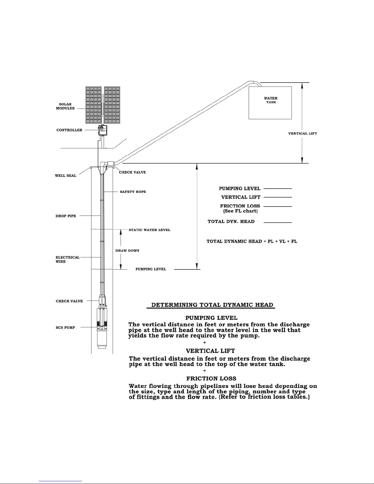
The PC-series controller can either be mounted indoors or outdoors. Locate all system equipment as close
as possible to each other. Generally the controller is mounted on the north side of a pole which has solar
electric modules mounted on top of it. The controller must be mounted in a vertical position for proper
cooling and to keep the electronics dry. The pole should be located close to the well (bore hole). This
general physical layout is conducive to clean installation aesthetically and electrically.