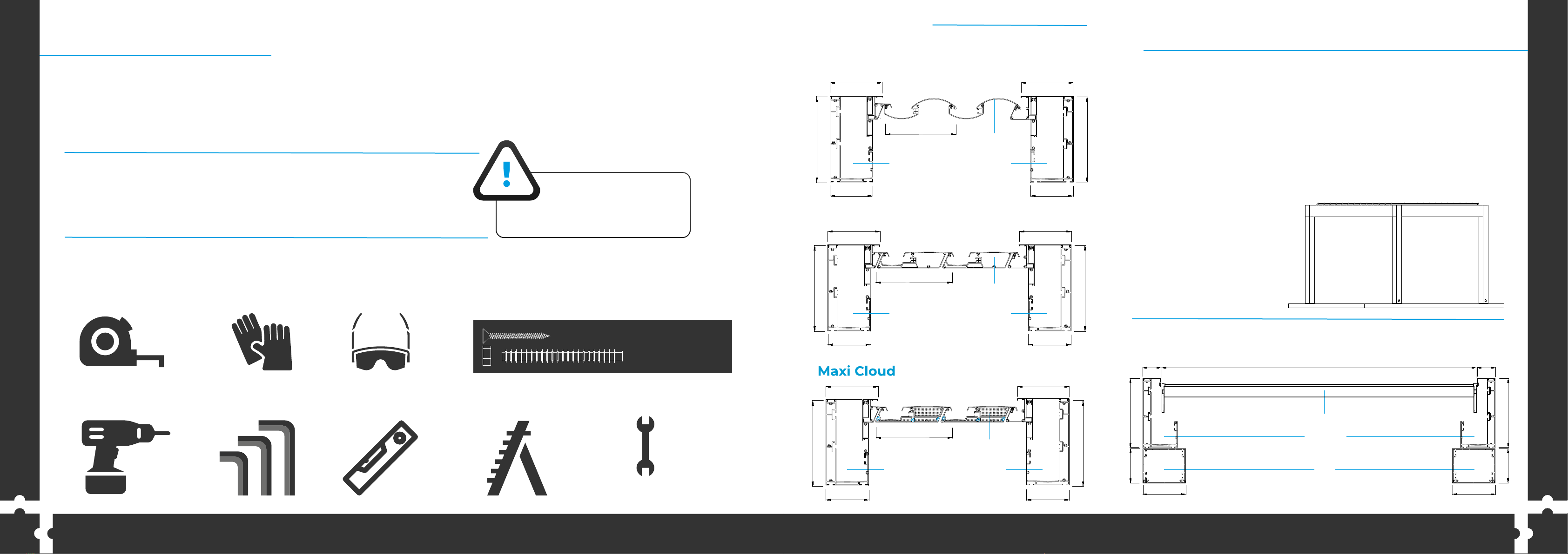
Product Section View
Information:
Below the page, you can check the A-A cross-section
of the SKYCLOUD system and below that B-B cross-section.
This section view includes every detail of the connection
of the parts. You can check every supporting
part against impact and leak (like water or air)
A-A
B-B
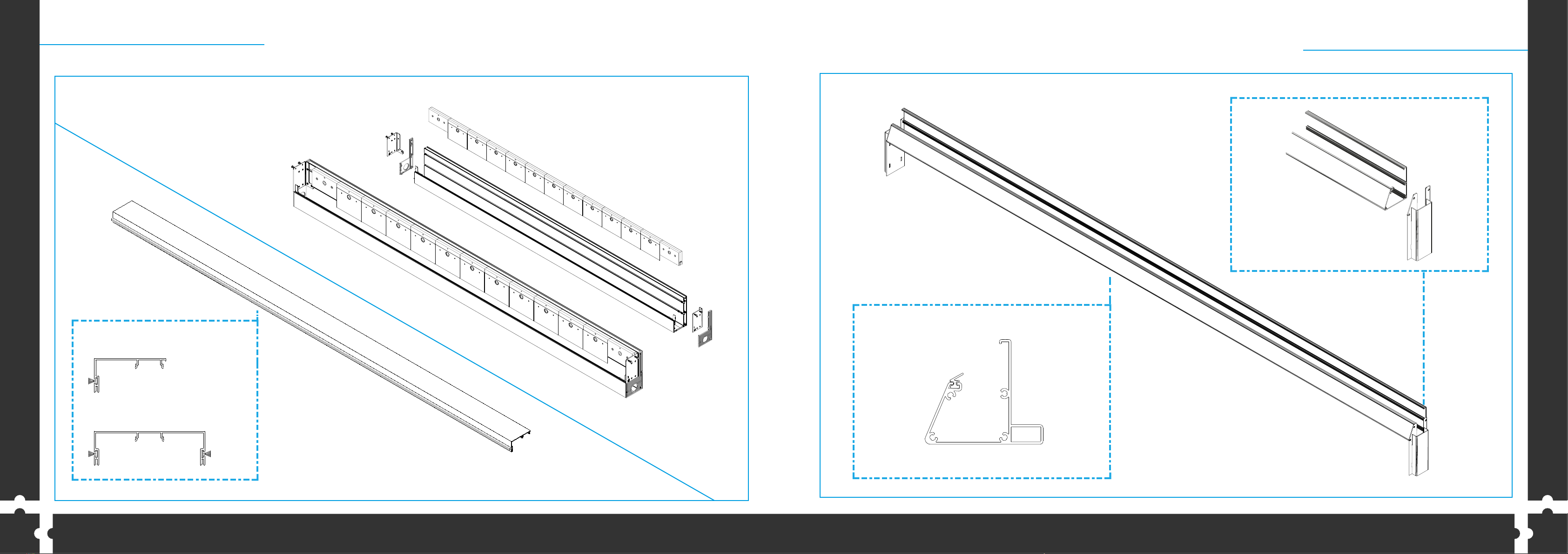
FRONT GUTTER
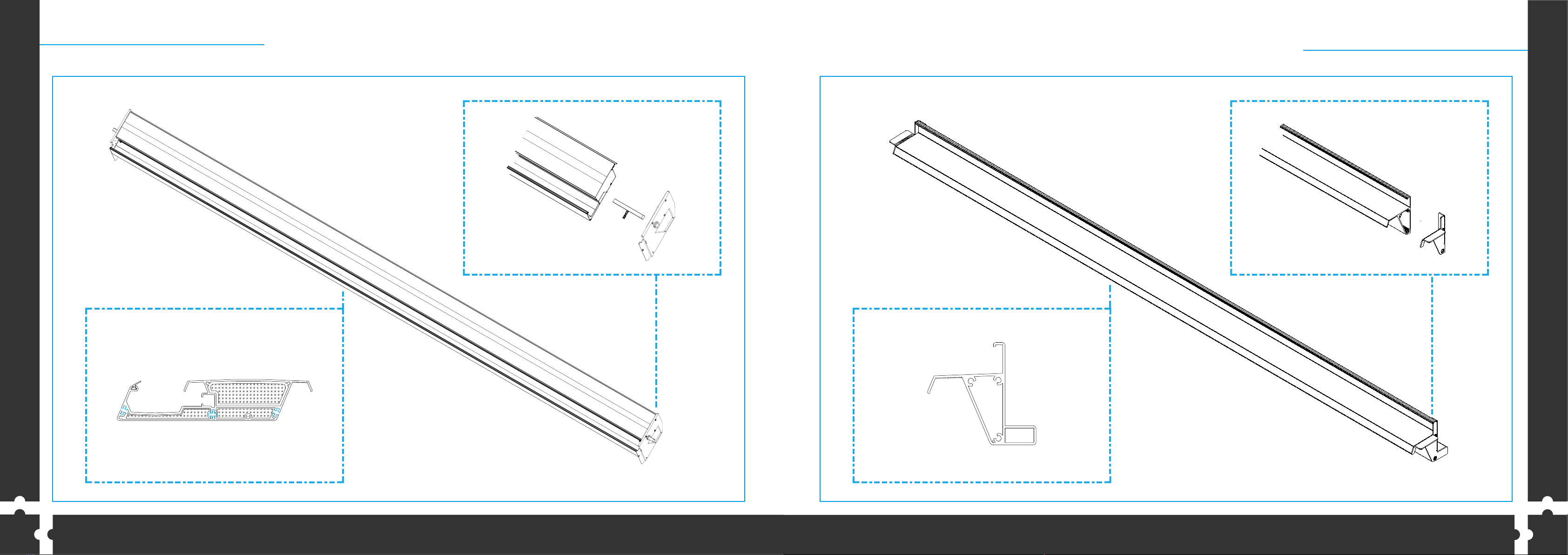
PANEL
BACK GUTTER PILLAR
RAIL PROFILES
PANEL
267
267
133 133
162 162
267
267
133 133
162 162
240
222
Eco Cloud
Active Cloud
165165
267
267
133
133
7070 Project-dependent
FRONT GUTTER
PANEL
BACK GUTTER
FRONT GUTTER
PANEL
BACK GUTTER
2
Thank you for purchasing Sunset Pergola Product.
These instructions include helpful hints and important information needed to safely assemble and properly
main- tain the Product. Please read these instructions completely before you begin and follow the steps
in the order they are presented.
1. Make sure you have all the necessary parts.
2. Lay the parts out in separate staging areas.
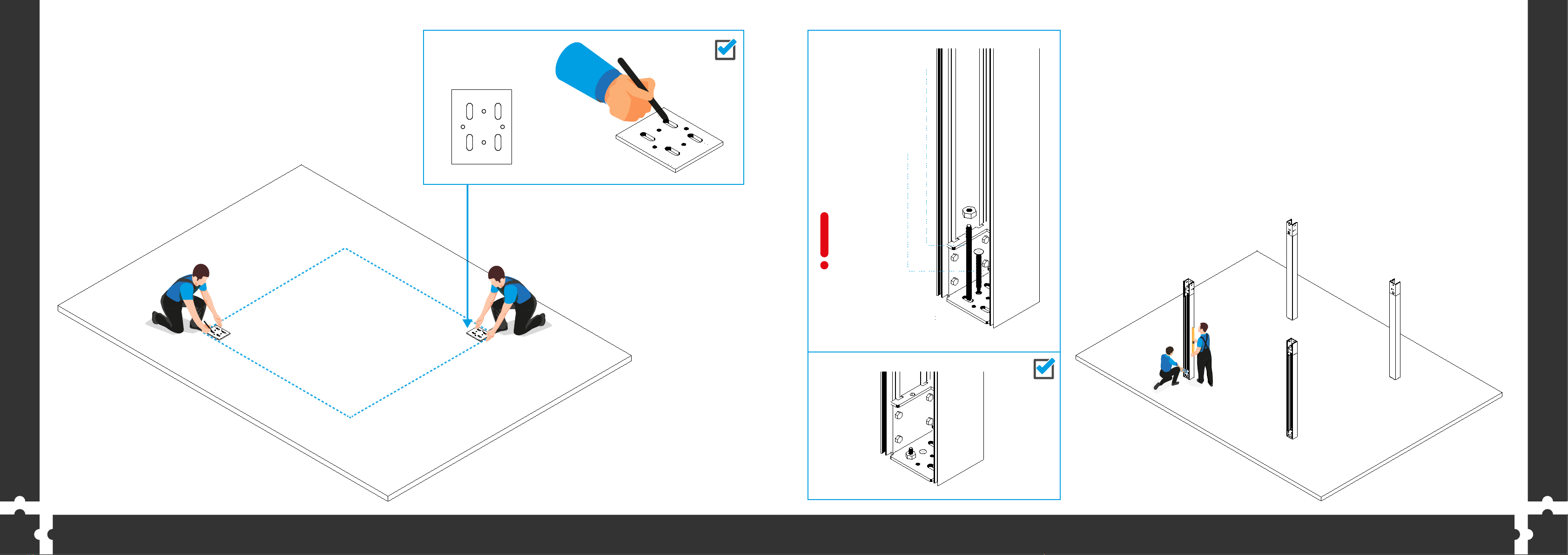
3. Select a Location.
4. Prepare a Foundation. (if necessary)
5. Make sure you have the proper tools:
•Tape Measure •Work Gloves •Safety goggles
•Drill •Hex Key •Spirit Level •2 Small Step Ladders •Wrench
•Concrete Screw - Buldex
Threaded Rod & Somun
7.5 x 120 / 7.5 x 150 / 7.5 x 180
10 x 90 ( for soft grounds )
ATTENTION:
DO NOT ATTEMPT
TO ASSEMBLE ALONE!
Introduction
1
267
267
133 133
162 162
240
13 mm
3 mm
4 mm
5 mm