Thank you for purchasing Sunset Pergola Product.
Introduction
İ
These instructions include helpful hints and important information needed to safely assemble and properly
main- tain the Product. Please read these instructions completely before you
begin and follow the steps in the order they are presented.
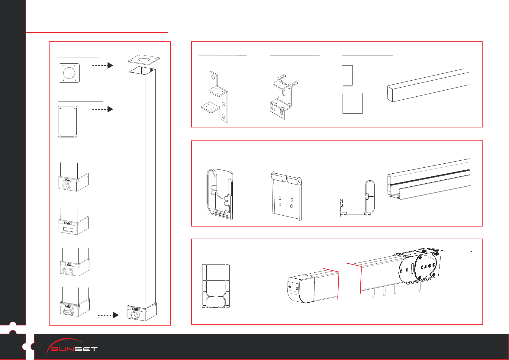
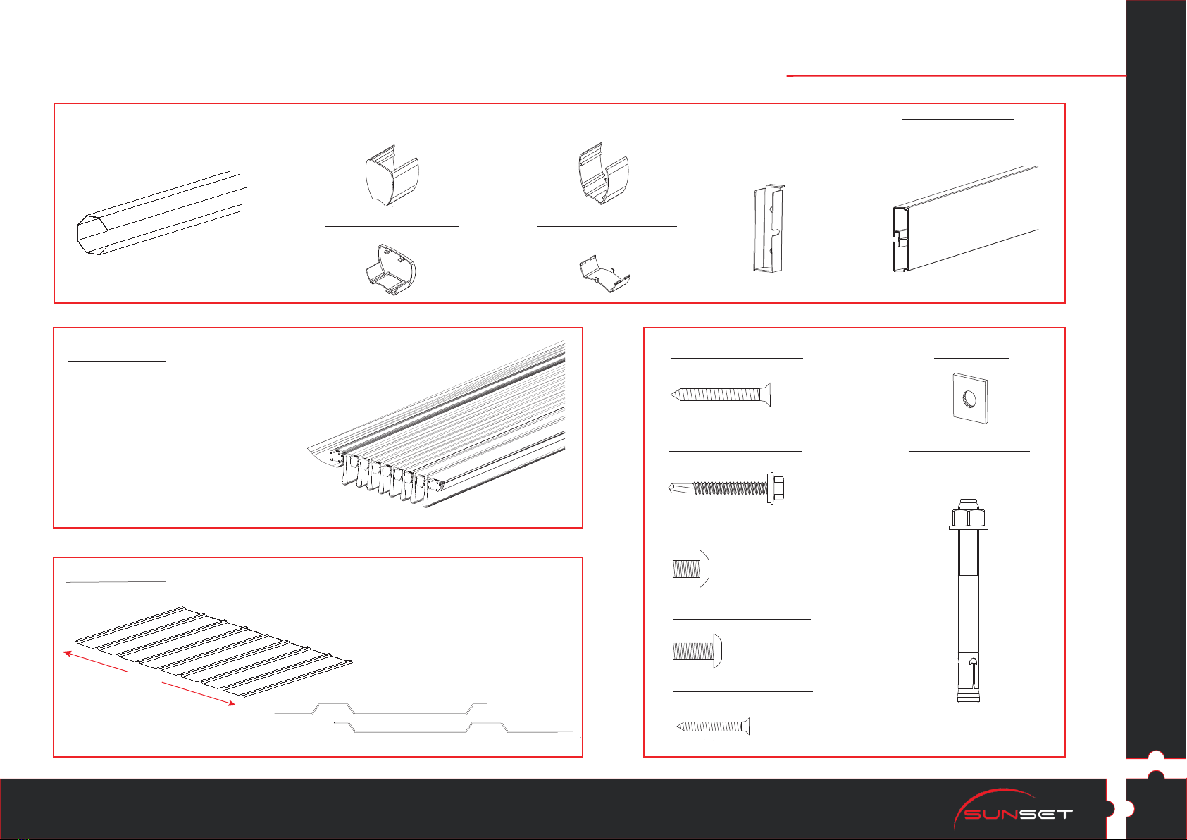
1. Make sure you have all the necessary parts.
2. Lay the parts out in separate staging areas.
3. Select a Location.
4. Prepare a Foundation.
5. Make sure you have the proper tools:
• Tape Measure
• Work Gloves
• Safety goggles
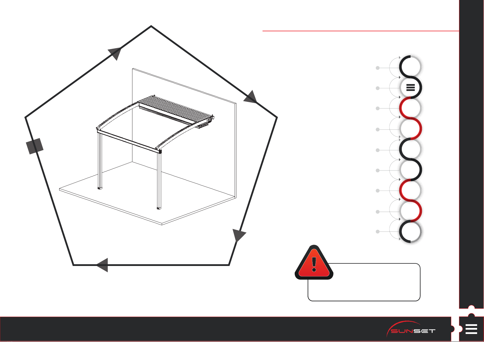
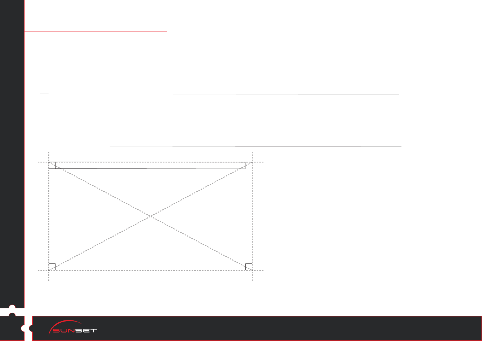
Projection
Width / Frontside
Wall / Backside
Diagonal 1
Diagonal 2
• Screwdriver
• Spirit Level
• 2 Small Step Ladders
On the left, you can see a plan
view of your field where you're gonna
set up your Pergola. This plan includes
only front pillars and backside parts
(Steel Rectangular Profile, Wall-Connectors).
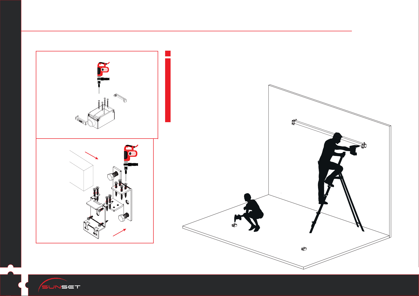
Carefully install ground level and wall
connection parts. Check projection,
width measure twice and
Diagonal 1 must be equal to Diagonal 2.
* Based on Gold Product type for detail models, Diamond
product type for general views.