Sunshine Solar Rutland 914i User manual

Rutland 914i Windcharger Installation & Operation
Doc No:SM-137 Iss. E 11.03.19 1 Marlec Eng Co Ltd
Rutland 914iWindcharger
(12 or 24 V )
Owners Manual
Installation and Operation
Doc No: SM-137 Iss. E 11.03.19
www.sunshinesolar.co.uk

Rutland 914i Windcharger Installation & Operation
Doc No:SM-137 Iss. E 11.03.19 2 Marlec Eng Co Ltd
This page is intentionally blank

Rutland 914i Windcharger Installation & Operation
Doc No:SM-137 Iss. E 11.03.19 3 Marlec Eng Co Ltd
Contents Page:
Introduction 4
Summary of Features and Uses 4
Profile and Dimensions 4
General Guidelines and Warnings 5
Check You Have Received 6
Other Items 7
Exploded View of the Rutland 914i 7
Assembly & Installation
Twelve Step Quick Start Guide 8
Tower Preparation 9
Blade Assembly 9
Tail and Nose Assembly 10
Electrical Connection & Fitting to the Tower 11
Up & Running
Four Point Checklist 11
Typical Wiring Diagrams for the Rutland 914i Windcharger 12
Siting the Windcharger
General Considerations 13
Mounting The Windcharger
On Board Systems 14
Land Based Systems 15
Further System Requirements
Batteries 16
Cable Specifications 16
Specification & Performance
Guideline Performance Curve 17
Maintenance & Troubleshooting
Inspection & Maintenance 18
Troubleshooting 19
Installation Instructions (abbreviated) - French 21
Installation Instructions (abbreviated) - Spanish 24
Installation Instructions (abbreviated) - German 27
Installation Instructions (abbreviated) - Italian 30
For Your Records 33
Limited Warranty 34

Rutland 914i Windcharger Installation & Operation
Doc No:SM-137 Iss. E 11.03.19 4 Marlec Eng Co Ltd
Introduction
Congratulations and thank you for purchasing your Rutland 914i Windcharger. The
utmost of care goes into the manufacture of all our products in our ISO9001
approved factory. To ensure you get the very best out of the Rutland 914i we
recommend that you read this manual and familiarise yourself with its contents
before installing and operating the Windcharger system.
Summary of Features and Uses
Aerodynamically improved to maintain good wind flow and stability.
Maximum power point tracking technology yields up to 30% more power than the
Rutland 913.
Low wind speed start up maximises power generation in more typical low winds.
High grade construction materials for durability, U.V. stability and weather
resistance.
Provides a D.C. power supply to charge 12 or 24 V battery banks.
Designed for use on board sailing yachts, short term and supervised installations
on motor caravans and static caravans where low power is needed.
Note: Other Rutland Windcharger models are designed for permanent installations
on land - contact Marlec or visit www.marlec.co.uk to find out more.
Rutland 914i Profile & Dimensions
Fig 1

Rutland 914i Windcharger Installation & Operation
Doc No:SM-137 Iss. E 11.03.19 5 Marlec Eng Co Ltd
General Guidelines & Warnings
Mounting pole outside diameter MUST NOT exceed 48.5mm for at least the top
0.5m. Larger section poles must not be used as this will reduce the tower to blade
clearance. In high wind conditions this could cause damage to the Windcharger by
allowing the blade to come into contact with the mounting pole. A broken blade will
cause turbine imbalance with consequent damage.
When turning, the Windcharger is capable of generating voltages in excess of the
nominal voltage. The turbine must never be allowed to rotate unless it is
electrically connected to a regulator or batteries. Connecting an open circuit
running turbine to the electrical system can cause serious damage to system
components owing to excessive voltage. Caution must be exercised at all times to
avoid electric shock.
Stopping the turbine – this may be necessary to undertake battery maintenance. If
possible stopping the turbine should be done in low wind speed conditions. The
turbine can be slowed by rotating or orienting the tail fin upwind, this will slow the
turbine sufficiently for it to be safely secured to the pole with rope. Avoid leaving
the turbine tied up for any period of time, we recommend that the turbine either be
covered to give protection from the weather or removed and stored in a dry
location. We recommend the use of Marlec charge regulator that includes a
shutdown switch.
Choose a calm day to install the equipment and consider other safety aspects. No
attempt to repair the system should be made until the wind generators restrained
from turning.
The Windcharger is fitted with ceramic magnets, which can be damaged by heavy
handling. The main generator assembly should be treated with care during transit
and assembly.
It is essential to observe the correct polarity when connecting the Windcharger and
all other components into an electrical circuit. Reverse connection will damage the
Windcharger and incorrect installation will invalidate the warranty.

Rutland 914i Windcharger Installation & Operation
Doc No:SM-137 Iss. E 11.03.19 6 Marlec Eng Co Ltd
The Rutland 914i Windcharger is suitable for use on board sailing boats. When
storm winds are forecast the turbine can be restrained to minimise wear and
tear. In particularly when boats are in dry dock the shutdown switch of the
selected charge regulator should be in the off to prevent the turbine from
turning at full speed.
If in doubt, refer to your dealer, a competent electrical engineer or the
manufacturer.
Check You Have Received - See Rutland 914i Exploded View
24 x No.10x25mm special self-tapping screws for aerofoil blades
1 x No.4 x 13mm self tapping screw for tail bracket covers
2 x M6 x 16mm Hex. Head screws for tail fin
2 x M6 nylock nuts for tail fin
1 x main generator assembly
6 x aerofoil blades
1 x tail fin
2 x tail bracket covers
1 x nose cone + 3 x nylon fixing screws
1 x 2-way terminal block
2 x M10 Hex Head Screws
2 x tab washers
In the event of loss or damage, consult your dealer or the manufacturer.

Rutland 914i Windcharger Installation & Operation
Doc No:SM-137 Iss. E 11.03.19 7 Marlec Eng Co Ltd
Other Items
What You Will Need - Tools
Suitable wire stripper
Small terminal screwdriver
Large flat blade screwdriver
Crosshead screwdriver
10mm Spanner or Socket
17mm Spanner or Socket
Other Items You May Have Selected
HRSi or HRDi Charge Regulator
Optional HRDi Remote Display
2 Core cable according to the Cable Specification table in this manual
Rutland 914i Marine Mounting Kit and Stays Kit ( CA-12/02 & CA-12/32 )
Short section of stainless steel tube to adapt into your own mounting design.
Other Items You Will Need
Mounting pole
Cable
Batteries
Battery terminals
Connector blocks (as determined
by your total system)
Exploded View of The Rutland 914i
Nose Cone
With 3
Screws
Six Blades with
24 Screws
Nacelle Dome
Generator Hub
Post Adaptor
Tail fin

Rutland 914i Windcharger Installation & Operation
Doc No:SM-137 Iss. E 11.03.19 8 Marlec Eng Co Ltd
Assembly and Installation
Twelve Step Quick Start Guide
1. Choose an open site to expose the Windcharger to a clear flow of wind and avoiding
obstructions. On board mount the Windcharger at least 2.4 metres above the deck and on
land at least 4-6m high. Read the full section on Siting.
2. Choose a mounting pole with an internal diameter of 41.0mm and external diameter of
no greater than 48.5 mm for the top 0.6m minimum to (i) prevent accidental damage and
(ii) meet warranty conditions.
3. Mount a charge regulator, from the Marlec range, to a suitable vertical surface and close
to the battery. Follow instructions supplied with the charge regulator.
4. Drill the mounting pole, if required, in preparation to accept and secure the
Windcharger. See Assembly and Installation section.
5. Choose suitable two core cable to connect from the Windcharger to the regulator. Up to
20m this should be of at least 2.5mm² cross sectional area. A short section of 4mm² cross
sectional area is required to link the regulator to the battery. For other distances see the
table in Cable Specifications.
6. Position the mounting pole ( this may be done on the ground before raising the pole ) so
that the selected cable can be threaded along it.
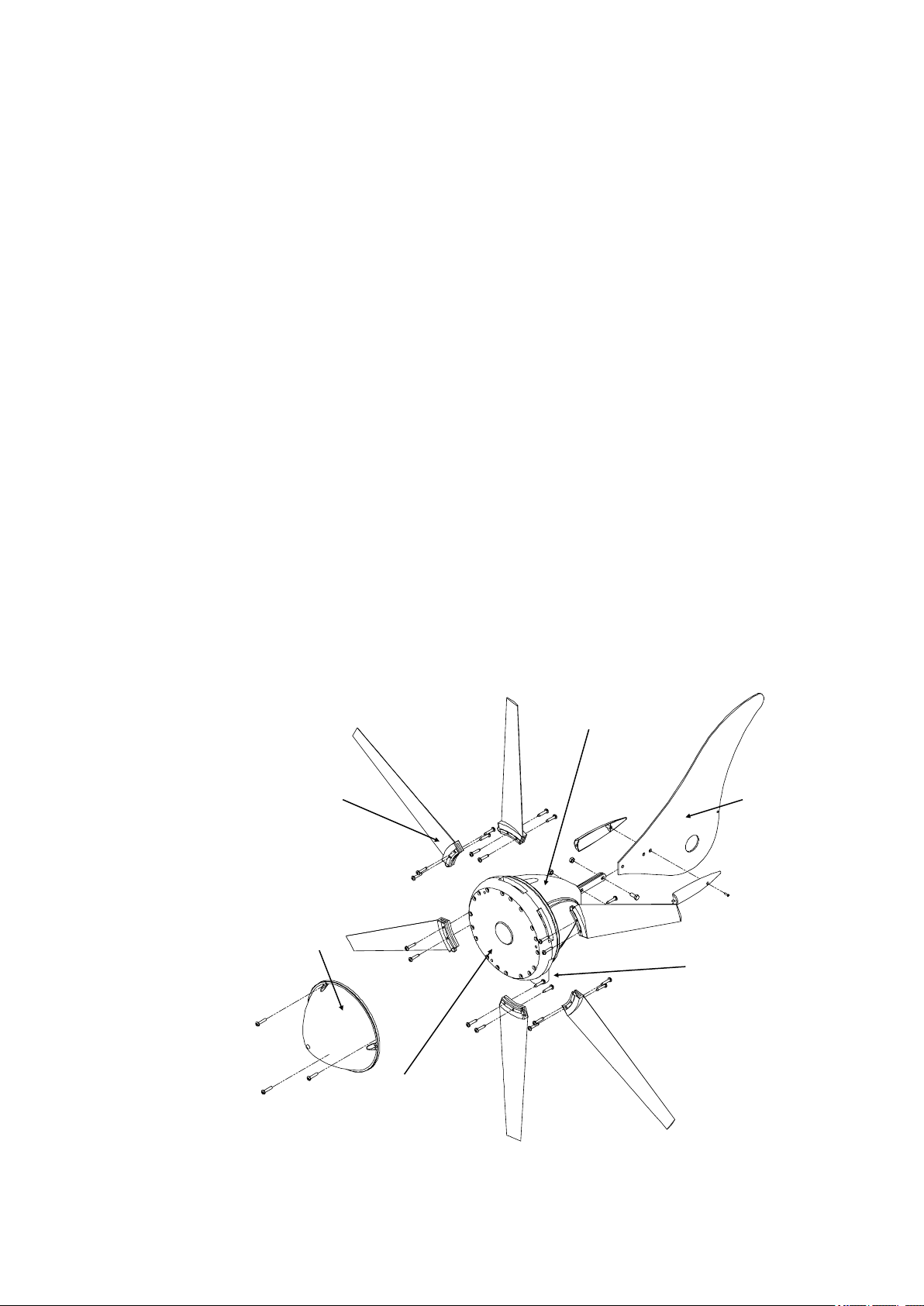
7. Fit the blades, tail and nose to the Windcharger using fasteners provided. It is
essential that 4 screws are fitted per blade.
8. Join the cable threaded through the pole to the Windcharger output cable using the
connector block provided. Wrap with insulating tape. Alternatively use a latching plug and
socket. We recommend looping back the cable and securing with a cable tie to provide
strain relief to the joint.
9. Carefully push the cables down the pole whilst sliding the post adaptor down the pole.
Line up the holes and secure in place with the hex head screws and tab washers
provided. The tab washer long part should be shaped to curve around the pole and the
short tab wrapped flat onto one hex head flat to prevent the hex head from loosening in
service. Do not allow the turbine to spin freely.
10.Locate the charge regulator close to the batteryand carefully follow ALL the regulator
guidelines and installation sequences for connecting the Windcharger through to the
battery.
11.Ensure that the battery connections are permanent as the Windcharger should NEVER
be operated without a connection to the battery.
12.Raise and secure the Windcharger. It can now be allowed to rotate. Follow the
“ Up and Running- Four Points Final Checklist” featured later. Also the
“ General Guidelines and Warnings” section expands on the above points.

Rutland 914i Windcharger Installation & Operation
Doc No:SM-137 Iss. E 11.03.19 9 Marlec Eng Co Ltd
Blade Assembly (Fig.3)
1.Place the generator assembly on a flat surface
hub-side down. Position blade as shown. The
blades will only fit one way around.
2. Insert the protrusion at the trailing edge of the
blade root fixing first into the socket to align with
the corresponding recess in the blade socket.
The blade can then be inserted with a lever
action. A soft faced mallet may be used to tap
the end of the blade to assist in fully locating the
blade.
3. First fit each blade with two special self-tapping screws provided to the rear of
each blade by inserting each in turn through the cut out in the nacelle, rotating the
generator each time until the holes align. Fit the remaining blade screws from the
front of the generator hub. Check tightness of all screws but do not over-tighten.
Caution- It is essential that all 4 screws are fitted!
Tower Preparation (Fig.2)
Select a suitable pole from the suggested
guidelines in Mounting the Windcharger.
Note that the post adapter fitted to the 914i
is designed to fit inside a standard 41mm
(1⅝”) internal diameter tube.
The adapter is provided with a flat on one
side to clear the weld seam on seamed pipe.
Alternatively the blades, tail and nose dome can be fitted after mounting the
generator assembly to the tower.
Fig. 3
2. Mark and centre-punch two positions diametrically opposite, at 90° to the pipe
seam if necessary, 20mm from top of the tube
Note: Use metric measurements for this operation
3. Drill two holes 10.5mm in diameter on centre-punch positions.
Note :Use metric measurements for this operation
Note: When using Rutland 914i Mounting Kit , items 2 and 3 can be ignored as
Marlec supplied poles are pre-drilled.
Assembly and Installation Detailed Instructions
Fig.2

Rutland 914i Windcharger Installation & Operation
Doc No:SM-137 Iss. E 11.03.19 10 Marlec Eng Co Ltd
4. Fit the plastic nose dome in position on the front of the generator hub and
secure in place with the three nylon screws provided.
5. You may now mount the Rutland 914i to the tower if you have not already done
so.
Fitting The Tail and Nose Assembly (Fig.4)
Tail Brackets
Tail Bracket Covers
Tail Fin
Nacelle Fig.4
1. Slide the tail fin between the two tail brackets lining up all drilled holes.
2. Locate the two screws provided through the appropriate holes and secure
with nuts.
3. Locate the tail bracket covers into the nacelle grommet whilst positioning the
processes for the fixing screw into the appropriate drilled hole in the tail.
4. Secure with the self tapping screw provided.

Rutland 914i Windcharger Installation & Operation
Doc No:SM-137 Iss. E 11.03.19 11 Marlec Eng Co Ltd
Electrical Connection and Fitting to The Tower
1. Run the cable selected (see Table 1) down the inside of the pole.
2. Select one of the 2 basic wiring systems on page 12 and follow the manual
provided with the voltage controller.
3. Connect the Windcharger flying leads to the cable protruding from the tower using
the connector block supplied, taking care to observe polarity. Connect the
Windcharger + to cable + and Windcharger – to cable –
Red is + Positive
Black is - Negative
4. Wrap the connection with insulation tape to secure/protect from environment.
Alternatively join the cables using a latching-type plug and socket.
5. Locate the Windcharger post adaptor into the tower whilst gently easing the cable
from the tower base to ensure the cable is not trapped.
6. Secure the Windcharger to the tower using the hex head screws and tab washers
provided. Bend and press the short tab of the washer against a flat on each screw
head to prevent screws from working loose in service. Bend the long tab of the
washer so that it follows the circumference of the pole, tap lightly with a mallet to
maintain the curve. Refer to figure 2.
Up and Running
Four Point Final Checklist
Before raising and securing the wind generator:
1. Check the tightness of the blade & tail fixing screws and generator mounting
screws.
2. Check free rotation of the hub and yaw axis.
3. Check that the cable is not trapped.
4. Check that all electrical connections are secure and safe.
The Windcharger can now be raised into position.
Take care to avoid all moving parts when raising and lowering the Windcharger.
When raised, secure the structure firmly in an upright position.
Caution-The performance of your Windcharger will be impaired if the pole is not vertical.

Rutland 914i Windcharger Installation & Operation
Doc No:SM-137 Iss. E 11.03.19 12 Marlec Eng Co Ltd
HRSi Charge
Regulator
12/24 V
HRDi Charge
Regulator
12/24 V
Solar Panel
Maximum
160 Watts
Solar Panel
Maximum
160 Watts
Typical Wiring Diagrams For The Rutland 914i Windcharger
Typical Wiring Scheme For A Single Battery Bank
Typical Wiring Scheme For Single or Dual Battery Banks
Second battery
optional

Rutland 914i Windcharger Installation & Operation
Doc No:SM-137 Iss. E 11.03.19 13 Marlec Eng Co Ltd
Siting The Windcharger
General Considerations
The location and height of the mounting pole or tower for your wind turbine will be the
major factor in the overall performance of your system. The smooth flow of wind
over land and water is often interrupted by a multitude of
obstructions causing wind sheer and turbulence.
Wind shear describes the interference between the fast moving upper air and the
slow moving air close to the ground and the resulting decrease in average wind
speed as one gets closer to the ground.
Turbulence is caused by the wind passing over obstructions such as moored boats,
trees, and buildings.
Both wind sheer and turbulence diminish with height and can be overcome simply by
putting the turbine sufficiently high above them as shown in Fig 4a. Wind speed
decreases and turbulence increases where obstructions exist. Consider also that
downwind obstructions can be as detrimental to performance as upwind obstructions.
It is therefore essential that the wind generator should be located in an area as free
as possible from disturbed wind flow.
WIND DIRECTION
AREA OF TURBULENCE
20H2H
2H
H
Fig. 4a

Rutland 914i Windcharger Installation & Operation
Doc No:SM-137 Iss. E 11.03.19 14 Marlec Eng Co Ltd
On Board Systems
The wind generator should be mounted in a safe
position, a minimum of 2.3 metres (7.6 feet) above the
deck and away from other obstacles which could
interfere with the blades or tail assembly (Fig. 5).
The Rutland 914i Mounting & Stays Kits (Part No.
CA-12/02 & CA-12/32) are available for deck mounting,
or short sections of stainless steel tube of 1200mm (47”)
and 600mm (23”) pre-drilled are also available for your
own fabrication.
The Rutland 914i is designed to fit inside an
aluminium or stainless steel tube with an internal
diameter of 41mm (1⅝”). IMPORTANT: The external
diameter MUST NOT exceed 48.5mm (1⅞), see
Warning in Introduction.
Suitable tubes: Stainless Steel 13/4”16 SWG and
Aluminium 17/8” 10 SWG
We suggest the following mountings according to
preference and site conditions:-
Push pit (Fig.6)
A suitable pole mounted to the deck with deck plates
and solid guys is the most popular method of mounting
the Windcharger on yachts, eg. Rutland 913 Mounting &
Stays Kit.
Mizzen (Fig.7)
Mizzen mounting is suitable on larger yachts, taking
advantage of greater wind flow the higher the wind
turbine is mounted.
River Boats (Fig.8)
A pivot pole is ideal for riverboats as the Windcharger
can easily be raised and lowered.
Fig. 5
Fig. 6
Fig. 7
Fig. 8
Mounting The Windcharger

Rutland 914i Windcharger Installation & Operation
Doc No:SM-137 Iss. E 11.03.19 15 Marlec Eng Co Ltd
Land Based Systems
The Rutland 914i is suitable for use at supervised land
based temporary and leisure applications. The
Furlmatic Windcharger model is designed and
recommended for off-grid land locations.
The Rutland 914i is designed to fit inside
aluminium, stainless or steel tube with an internal
diameter of 41mm. (1⅝”). IMPORTANT: The external
diameter MUST NOT exceed 48.5mm (1⅞), see
Warning in Introduction.
A suitable mounting pole can be erected using a 6.5
metre (21 feet) galvanised (medium) tube. The tube
must be supported by a minimum of four guy lines.
The attachment points for the guy lines to the tower
should be securely fixed to the tower.
The guy wires should be a minimum of 4mm
(0.16”) in diameter.
The shackles should be a minimum of 5mm (0.20”)
in diameter.
Rigging screws should be a minimum of 5mm
(0.20”) in diameter.
All items should be galvanised or stainless steel for
protection against corrosion.
Where guy lines are looped, the loop must
incorporate a thimble and be fitted with a
minimum of three rope grips.
All ground fixings must be made suitable
according to the terrain.
We suggest pivot type towers as these allow for easier
installation and lowering for access to the wind
generator. Two forms of pivot tower are suggested in
Figs 9 & 10.
A base-hinged 6.4m tall Land Tower Kit (Part No:
CA-12/08) and Rigging Kit (Part No:CA-12/07) are
available from Marlec.
Fig. 10
Centre pivoted pole
Base pivoted with gin pole
Fig. 9

Rutland 914i Windcharger Installation & Operation
Doc No:SM-137 Iss. E 11.03.19 16 Marlec Eng Co Ltd
Batteries
Leisure/Deep Cycle batteries are specifically
designed for good performance in terms of charge/
discharge cycles. Batteries are the most important
part of your battery charging system and should be
sized according to your load requirements and
provide at least 3 days reserve capacity. This will
reduce cycling, prolong the life of the battery and
ensure system reliability during periods of low wind.
Permanent connections should always be made to
the battery terminals. Never use crocodile clips or
similar devices.
We strongly recommend that one of the voltage
regulators available from Marlec is fitted to
prevent batteries becoming overcharged in strong
winds and is essential with gel/sealed batteries.
Batteries may be linked as shown in the figures 11
and 12. It is essential to observe polarity as
follows:
Red is + Positive
Black is - Negative
Cable Specification
Cable
Run
(m)
Cable Size
12V 24V
mm² AWG mm² AWG
0-20 2.5 13 1.5 15
21-30 4 11 2.5 13
31-45 6 9 4 11
46-80 10 7 6 9
Total = 12v
120Ah
1440Wh
In parallel to increase amp hours
In series to increase voltage
60Ah
12v
60Ah
12v
Total = 24v
60Ah
1440Wh
60Ah
12v
60Ah
12v
Further System Requirements
The cable used for connection of the
Windcharger to the batteries should be in
accordance with table 1. The use of a
smaller cable than recommended will
reduce the performance of the charging
system.
Cable and connectors are available from
your dealer or the manufacturer.
Fig 11
Fig 12

Rutland 914i Windcharger Installation & Operation
Doc No:SM-137 Iss. E 11.03.19 17 Marlec Eng Co Ltd
Specification and Performance
Guideline Performance Curve
Note : The curve shown below is for clear, non-turbulent wind conditions; this may
not be achieved in some installations. Refer to the section on Siting to optimise
performance at your site. Wind speeds are those flowing across the turbine of the
Windcharger and may not reflect those measured at mast top or those reported by
the Met. Office.
10
9
8
7
6
5
4
3
2
1
Charge into 24 V Battery (Amperes)

Rutland 914i Windcharger Installation & Operation
Doc No:SM-137 Iss. E 11.03.19 18 Marlec Eng Co Ltd
Maintenance and Troubleshooting
Inspection and Maintenance
The Rutland 914i requires no scheduled maintenance but an annual inspection
should be carried out to monitor the general condition of the system to ensure the
electrical and mechanical integrity and safety of the system.
WARNING! Before inspection, the turbine should either be lowered to the ground or
tied to prevent the generator from turning. To stop the generator from turning
proceed as follows:
1. Either rotate the switch to stall mode on the charge regulator if used OR turn the
wind generator out of the wind (180°) using the tail, a hole is provided in the tail fin
to assist in this. The generator will gradually slow down.
2. Tie a blade to the mounting pole to prevent it from rotating.
Whilst the generator is stationary, the following routine checks should be performed:
1. Check the blades for damage, eg chips or nicks. Replace any damaged blades.
The turbine should not be operated with damaged blades as this may cause
imbalance resulting in premature wear and possible failure. Check the blade
screws for tightness.
2. Check all other nuts, bolts and screws for tightness.
3. Check the yaw axis for free rotation.
4. Check tower assembly for condition.
5. Check the tension of the guy wires if applicable. The tension of guy wires
should be checked frequently during the first year.
6. The unit can be wiped with a mild detergent and rinsed with water to remove
dirt and debris.
Note: The Windcharger is designed for continuous running to achieve
maximum resistance to water ingress. Should you wish to take the unit
out of service for an extended period it is recommend that the unit be
removed from the mounting and stored in a dry location or covered.

Rutland 914i Windcharger Installation & Operation
Doc No:SM-137 Iss. E 11.03.19 19 Marlec Eng Co Ltd
Troubleshooting
In the unlikely event that your Rutland 914i should develop a defect, the turbine
should first be tied to prevent the blades from turning to perform the static tests
below. (Follow the procedure described in the Inspection and Maintenance
section) It will be necessary to let it run for the tests to check for power production.
Read the Electrical Connection and Up and Running sections and be satisfied
that your system complies.
Is there sufficient wind? The Rutland 914i needs 5 knots wind speed to start
charging. The wind speed across the turbine blades may be greatly reduced in a
marina or built-up area compared with the reading on a masthead anemometer
or weather reports.
Static Tests:
Is the battery in good condition? Check the voltage and electrolyte level of each
battery.
Check electrical continuity throughout the system, especially corrosion and
poor connections in cable joins and connector blocks.
Running Tests:
Check for power output from the windcharger, following this procedure:
1. Set a digital multimeter to DC Amps, scale of between 5 and 10 if possible.
Connect the meter positive (+) probe to the wind generator output positive cable
and the meter negative (-) to the regulator input positive. Provided there is
sufficient wind there should be a current reading. This establishes that power is
being delivered.
2. Using the same multimeter setting as above measure between the regulator to
battery + and the battery +. Provided there is sufficient wind there should be a
current reading. This establishes if power is passing through the regulator.
3. If both above are unsuccessful set the multimeter to DC Volts. Disconnect the
wind generator from the regulator and connect the meter + to the wind
generator + and the meter – to the wind generator -. Provided there is sufficient
wind there should be a variable voltage reading according to the speed of the
wind seen at the wind turbine. This will establish if the wind generator is able to
deliver power or not.
4. If tests 1 and 3 are successful but test 2 fails to produce results connect the wind
generator directly to the battery. Set the digital multimeter to DC Amps and
measure power between the wind generator + and the battery +. If a reading is
measured, providing there is sufficient wind, then the regulator is faulty.

Rutland 914i Windcharger Installation & Operation
Doc No:SM-137 Iss. E 11.03.19 20 Marlec Eng Co Ltd
5. If the wind turbine fails to deliver any current or open circuit V reading
undertake the further tests below.
6. Mechanical inspection. It may be necessary to remove the windcharger from
its pole for the following tests.
Check the brushes and slipring for wear or damage. To inspect the brushes,
remove the nacelle by removing the three fixing screws and slide the nacelle
backwards towards the tail fin. The brushes and slipring can be inspected by
removing the four self-tapping screws holding the brush holder assembly in place.
Remove any black deposits from slipring with emery paper. Heavy deposits and
reduced power indicate a possible reverse connection to the battery (see Page 11).
Check hub for free rotation with generator disconnected from battery.
If the hub does not rotate freely, check for a possible short circuit in the wiring. If no
wiring fault is found refer to your dealer or manufacturer.
If the above checks have identified a need for spare parts or failed to identify the
problem you should contact Marlec who can advise you of your nearest
distributor in their world wide network. In the first instance we recommend that you
contact the company from whom the product was originally purchased.
If in doubt, refer to your dealer or manufacturer.
Table of contents
Other Sunshine Solar Wind Turbine manuals