Sunshine Solar 914 User manual

Document No SM-412 Issue B 12.02.03
Rutland Windcharger 914 & FM910
Land Tower & Rigging Kit
Installation Instructions
www.sunshinesolar.co.uk

Document No SM-412 Issue B 12.02.03 1
CONTENTS
Page
INTRODUCTION……………………………………………………………2
CHECK YOU HAVE RECEIVED…………………………………………...3
WHAT YOU WILL NEED…………………………………………………..3
SITING……………………………………………………………………….4
FOUNDATIONS……………………………………………………………..5
Tower base…………………………………………………6
Guy Anchors……………………………………………….7
TOWER PREPARATION……………………………………………………8
ASSEMBLY…………………………………………………………………..9
ERECTION………………………………………………………………….10
APPENDIX A – TUBE DRILLING DETAIL………………………………11
APPENDIX B – SECTIONED TUBE KIT…………………………………12

Document No SM-412 Issue B 12.02.03 2
INTRODUCTION
This manual contains important information concerning your Rutland 914
/FM910 Windcharger tower and its installation.
It is strongly recommended that you read this manual and familiarise
yourself with its contents before installing and operating the Windcharger
system.
The complete kit is a base pivoted 6.5m high twin guyed tower, for easy
installation & erection by 2 people. The design complies with IEC1400-2.
The tower and rigging kits are available separately to allow the use of a
single length of tube (supplied by the user) with the rigging kit. The
customers own tower should be 40mm nominal medium (3.2 wall)
galvanised tube. Inside diameter 41.7mm, outside diameter 48.1mm.
Single length 6.5m.
WARNING!
It is recommended that erection of the tower is only attempted in light
winds.
Standard Health & Safety working practices and appropriate personal
protective equipment should be adopted during the following
procedures.
When using the WG914, mounting pole outside diameter MUST NOT
exceed 48.5mm. Larger section poles must not be used as this will
reduce the tower to blade clearance. In high wind conditions this could
cause damage to the windcharger by allowing the blade to come into
contact with the mounting pole.

Document No SM-412 Issue B 12.02.03 3
CHECK YOU HAVE RECEIVED
Rigging kit CA-12/07
Qty 2 - Tower Base brackets
Qty 2 - Base Foundation ‘U’ bolts, washers & nuts
Qty 4 - Guy Ground Anchors
Qty 2 - Guy Tower Brackets
Qty 2 - M8 x 65 Hex Head Bolts, Flat washers & Lock Nuts
Qty 1 - M10 x 70 Hex Head Bolt, Flat washer & Lock Nut
Qty 4 - 6.5m wire rope Guys with shackles fitted at looped end
Qty 4 - 4.5m wire rope Guys with shackles fitted at looped end
Qty 8 - Rigging Screws
Qty 4 - ‘D’ Shackles
Qty 8 - Thimbles
Qty 24 - Wire Rope Grips
Sectioned Tower kit CA-12/08
Qty 1 – Tube Top Section
Qty 1 – Tube Middle Section
Qty 1 – Tube Bottom Section
Qty 2 – Tube Joiners
WHAT YOU WILL NEED
Tape Measure
Spade
Concrete for foundations
13mm AF Spanner
17mm AF Spanner
8mm AF Spanner
Spirit Level
Other Items you will need if not using Sectioned Tower Kit
6.5m length of 40mm Medium (3.2 wall) galvanised tube.
Electric Drill
10.5mm Drill
8.5mm Drill

Document No SM-412 Issue B 12.02.03 4
SITING
General Considerations
The location and height of the mounting pole or tower for your wind
turbine will be the major factor in the overall performance of your
system.
The smooth flow of wind over land and water is often interrupted by a
multitude of obstructions causing wind sheer and turbulence.
Wind sheer describes the interference between the fast moving upper air
and the slow moving air close to the ground and the resulting decrease in
average wind speed as one gets closer to the ground.
Turbulence is caused by the wind passing over obstructions such as
moored boats, trees and buildings. Both wind sheer and turbulence
diminish with height and can be overcome simply by putting the machine
sufficiently high above them.
It is therefore essential that the wind generator should be located in an
area as free as possible from disturbed wind flow. Bear in mind that
downwind obstructions can be as detrimental to performance as upwind
obstructions (Fig.1).
Fi
g.1
WIND DIRECTION
AREA OF TURBULENCE
20H
2H
H
2H

Document No SM-412 Issue B 12.02.03 5
FOUNDATIONS
Note: The foundation dimensions given below are minimum based on normal
compacted cohesive soil, for other soil types the foundations should be designed
accordingly. If in doubt consult a civil engineer.
Mark out & dig holes for the tower base & four guy anchor points as shown in the
diagram below:
For added security, slope the sides of the holes outwards as shown in Fig 3
3.5m
Tower Base.
300mm x
300mm x
400mm dee
p.
Guy Anchors.
500mm x
500mm x
500mm deep.
Fig 2
Fig 3

Document No SM-412 Issue B 12.02.03 6
Tower base
Suspend the ‘U’ bolts centrally in the hole in the correct position & orientation. This
can be achieved using a suitable piece of wood which will span the hole, drill four
holes Ø12 using the tower base as a guide, insert the 2 base foundation ‘U’ bolts
through the holes & fit the 4 nuts ensuring that approx 30mm of thread protrudes
above the concrete. Foundation bolt spacing is 131 x 113mm.
Check for correct spacing of the foundation bolts by positioning tower base brackets
on the protruding threads & laying tower tube between the brackets prior to mixing
concrete.
Fig 4

Document No SM-412 Issue B 12.02.03 7
Guy Anchors
Select a suitable piece of wood which will span the hole, drill 1 hole Ø10.5 mm
through and secure the ground anchor to the wood at an angle of 45° using a suitable
bolt as shown in fig 5, suspend in the hole as shown ensuring they are in the correct
position & orientation.
Mix approx 0.5m³ of concrete & fill the five holes ensuring the concrete is well
packed down & air removed.
Ensure all inserts are correctly positioned & allow to harden for 2 days.
Note: The holes can be filled with concrete first and the foundation bolts & ground
anchors pushed in immediately afterwards if this is found to be easier.
Ground Level
45°
50mm
Fig 5

Document No SM-412 Issue B 12.02.03 8
TOWER PREPARATION
Using single 6.5m length of tube (not supplied) (Appendix A)
Drill tube as shown on drawing in Appendix A.
Insert 1 M8 x 65 bolt through the 8.5 hole at the lower guying position, fit &
tighten an M8 lock nut, orientate the nut & bolt so that the flats face the ends of
the tube.
Slide one of the guy plates over the top of the tube with the angled corners
pointing down, until it stops against the M8 nut & bolt.
Repeat the procedure for the upper guying point.
Using sectioned tower kit CA-12/08 (Appendix B)
See Appendix B for correct orientation of the tube sections.
Insert M8 x 65 bolts through the 8.5 holes in the top & middle sections of tube,
orientate the nut & bolt so that the flats face the ends of the tube.
Slide guy plates over the top of the top & middle sections of tube with the angled
corners pointing down, until they stop against the M8 nuts & bolts.
Join the 3 sections of tube using the joiners provided.
Fig 6

Document No SM-412 Issue B 12.02.03 9
ASSEMBLY
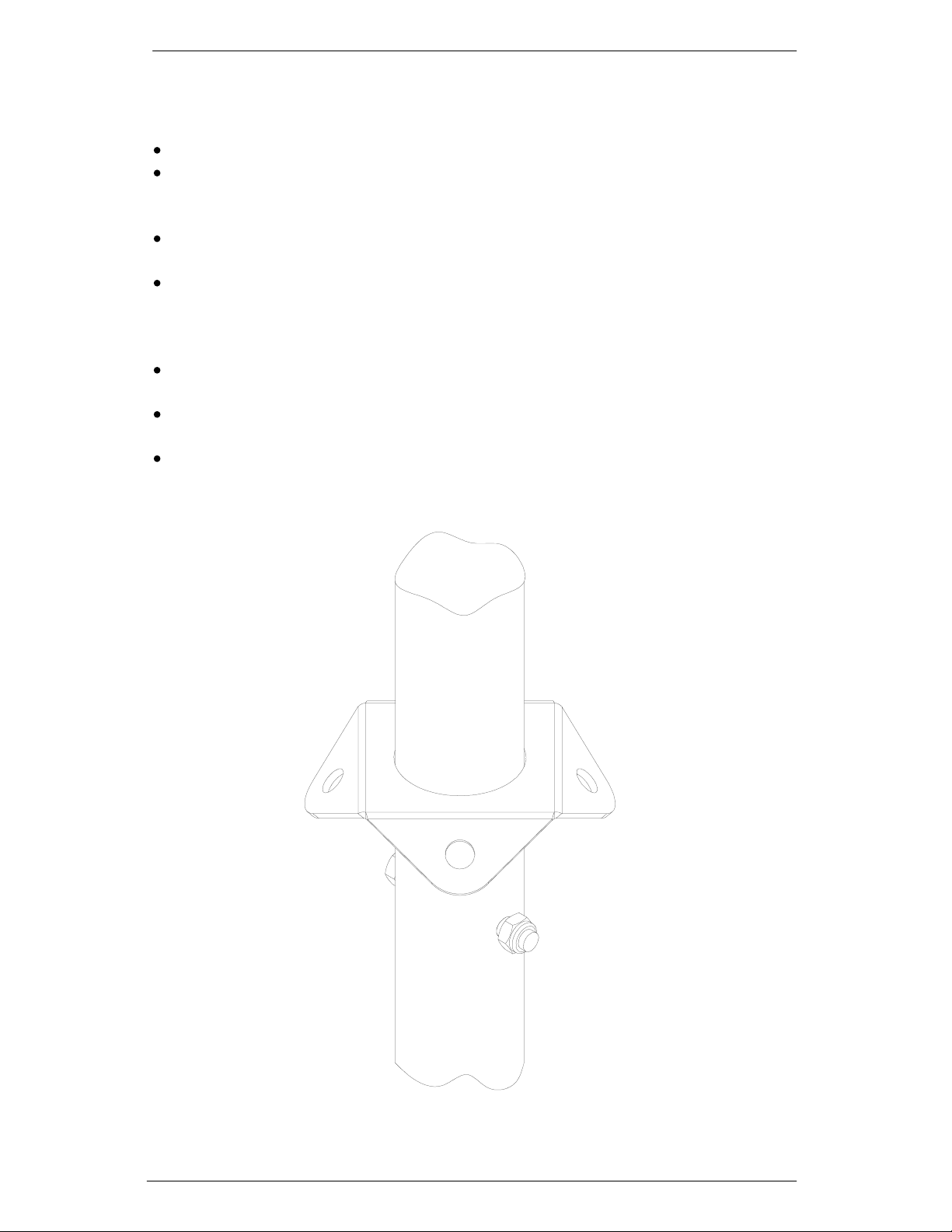
Place the Tower Base over the four threads protruding from the concrete foundation,
ensuring the pivot is orientated correctly. Fit the Nuts & washers & securely tighten.
Lay the tower tube in position on the ground with it’s bottom end in the tower base &
insert the M10 x 70 bolt, secure with the washer & nut ensuring the tube is free to
pivot.
Attach the guys to the guy plates with the shackles through the looped ends of the
guys, the 6.5m guys are fitted towards the top of the tube, the 4.5m guys towards the
bottom.
Fit the remaining 4 shackles to the guy ground anchors. Place the hooked ends of 2 of
the rigging screws through the shackles on the side anchor points. Open the rigging
screws to approx ¾ their maximum length.
Take the 2 upper side guys & pass the free ends through the looped ends of the
rigging screws & around the thimbles pulling the cables to remove the slack, secure in
position using 3 rope grips on each guy. Repeat the procedure with the fore & aft guys
by laying them alongside the side guys to achieve the same length.
Note: If the ground is uneven or not level, the guy lengths may differ.
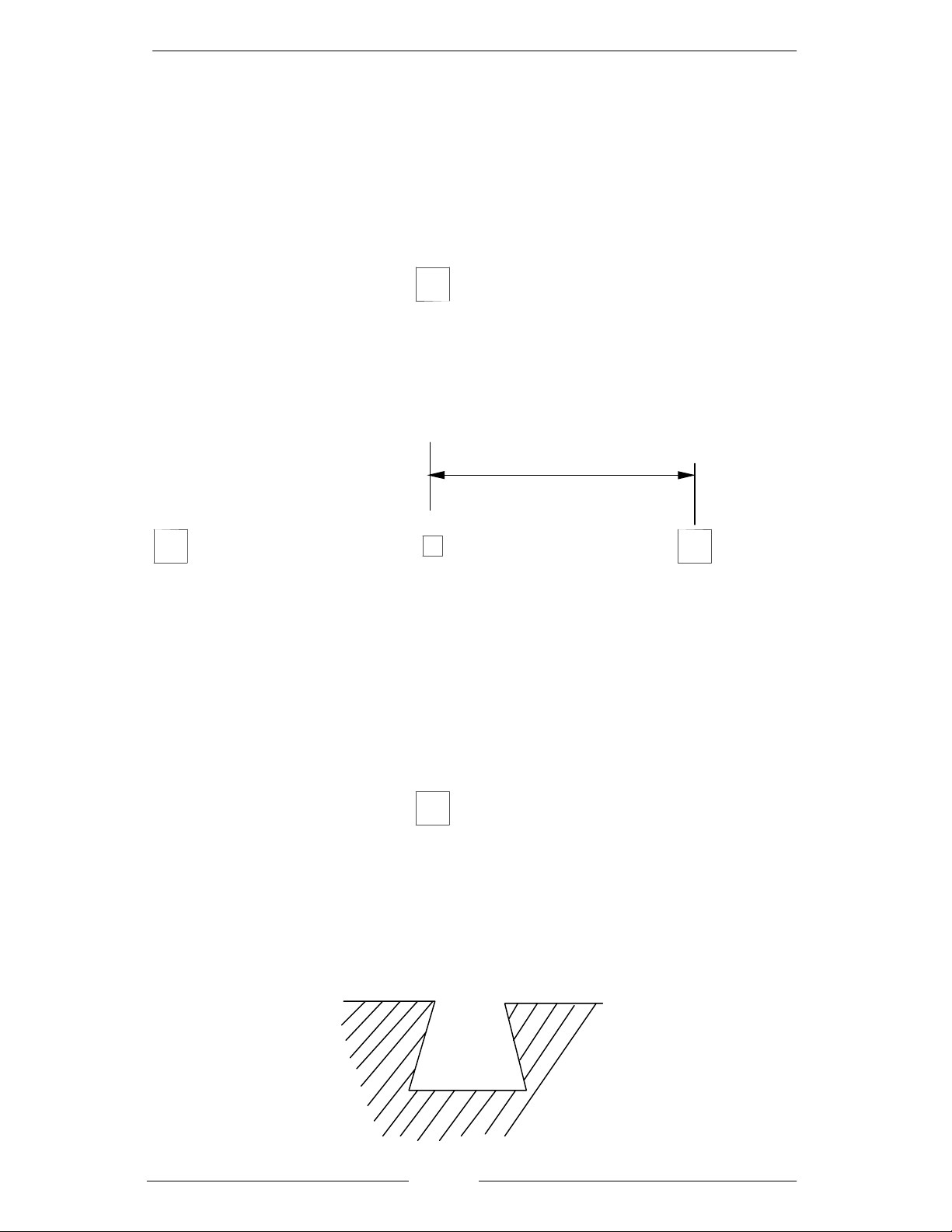
The first rope grip must be placed immediately against the thimble. The grips must be
placed so that they are separated by a minimum distance of 30mm. The ‘U’ bolt must
always be placed on the tail end of the rope ie non load bearing end.
Hook the rigging screw into the shackle on the anchor point for the rear guy, ie the
anchor point covered by the tower.
Fig 7

Document No SM-412 Issue B 12.02.03 10
ERECTION
Erection should only be attempted in light winds.
The tower should first be erected without the wind generator fitted.
Raise the tower to it’s working position by pivoting about it’s base fixing. Ensure the
rear rigging screw does not become detached from it’s anchor point. Attach the
free guy to it’s anchor point to secure the tower in it’s vertical position.
With the aid of a spirit level, adjust the rigging screws until the tower is vertical & the
guys are suitably tensioned.
Attach the 4 lower guys to their rigging screws by looping the free end through the
eye of the rigging screw and thimble & secure using 3 rope grips. Tension as for the
upper guys.
Ensure the tube is straight & vertical.
The tower can now be lowered by reversing the procedure for raising. It may be
necessary to slightly slacken the side guys during this procedure.
The wind generator cable can now be installed down the centre of the tower & the
wind generator fitted to the tower top. The tower can be raised in the same manner as
previously & guys tensioned ensuring the tower is straight & vertical.
After tensioning of the guys, the rope grip nuts should be checked for tightness, this
should be repeated after 24 hours. Further periodic checking & tightening of the nuts
is essential during service, more frequently during early stages of operation to ensure
long term reliability of the structure.

Document No SM-412 Issue B 12.02.03 11
Appendix A
Tube Drilling Detail

Document No SM-412 Issue B 12.02.03 12
Appendix B
Sectioned tube kit
This manual suits for next models
1
Table of contents
Other Sunshine Solar Wind Turbine manuals