SUNTAO SA MPI 5kW/15kWh User manual

All-In-One Energy Storage System User Manual
01

1.
Instructions Thank you very much for choosing the All-In-One Energy Storage Systemseries household energy storage
system developed and produced by our company. Please read and understand all contents of the Manual
carefully before installing and using the product. If you have any suggestions during the use, please do not
hesitate to give us feedback.
1.1
Range of Application The installation and user manual of All-In-One Energy Storage Systemseries is applicable to the installation
and use of the following products:
The product should be used in compliance with local standards, laws and regulations, because any non-
compliance with the use may lead to personal injuries and property loss.
The drawings provided in this Manual are used to explain the concepts related to the product, including
product information, installation guide, electrical connection, system debugging, safety information, common
problems and maintenance, etc.
The internal parameters of this product have been adjusted before delivery. No internal parameters can be
changed without permission. Any unauthorized changes to the settings will invalidate the warranty, and the
Company will not be liable for any loss resulting therefrom.
This Manual and other related documents are an integral part of the product and should be kept properly for
onsite installation personnel and related technical personnel to consult.
1.2
Meaning of Abbreviations
AC
Alternating Current
DC
Direct Current
PV
Photovoltaic
BMS
Battery Management System
PCS
Power Conversion System
RJ45
Registered Jack 45
SOC
State Of Charge
C
Charge C-rate
RS485
RS485 Communication Interface
CAN
Controller Area Network
No
Stacked
wall-mounted
1 SA MPI 5kW/15kWhVA MPI 5kW/5kWh2 SA MPI 5kW/20kWhVA MPI 5kW/10kWh
3
SA MPI 5kW/25kWh
4
SA MPI 5kW/30kWh02

1.3
Symbol Stipulations There may be following symbols herein, and their meanings are as follows.
Symbols Description
DANGER!
Indicate a hazard with a high level of risk which, if not avoided, will result in
death or serious injuries.
CAUTION
Indicate a hazard with a medium level of risk which, if not avoided, could
result in death or serious injuries.
ATTENTION
Indicate a hazard with a low level of risk which, if not avoided, could result in
minor or moderate injuries.
NOTICE
Warning information about device or environment safety. If not avoided,
equipment damage, data loss, performance degradation or other
unanticipated results may be resulted in. The "NOTICE" does not involve
any personal injuries.
2
Safety Precautions
2.1
Safety Symbols This product contains the following symbols, please pay attention to identifying.
Symbols Description
Observe enclosed documentation
Danger.
Risk of electric shock!
Danger of high voltages.
Danger to life due to high voltages in the Energy storage system
Hot surface
CE certification
Do not touch the product in 5mins after shutdown
Comply with RoHS standard
The Energy storage system should not be disposed together with the
household waste.
03

2.1
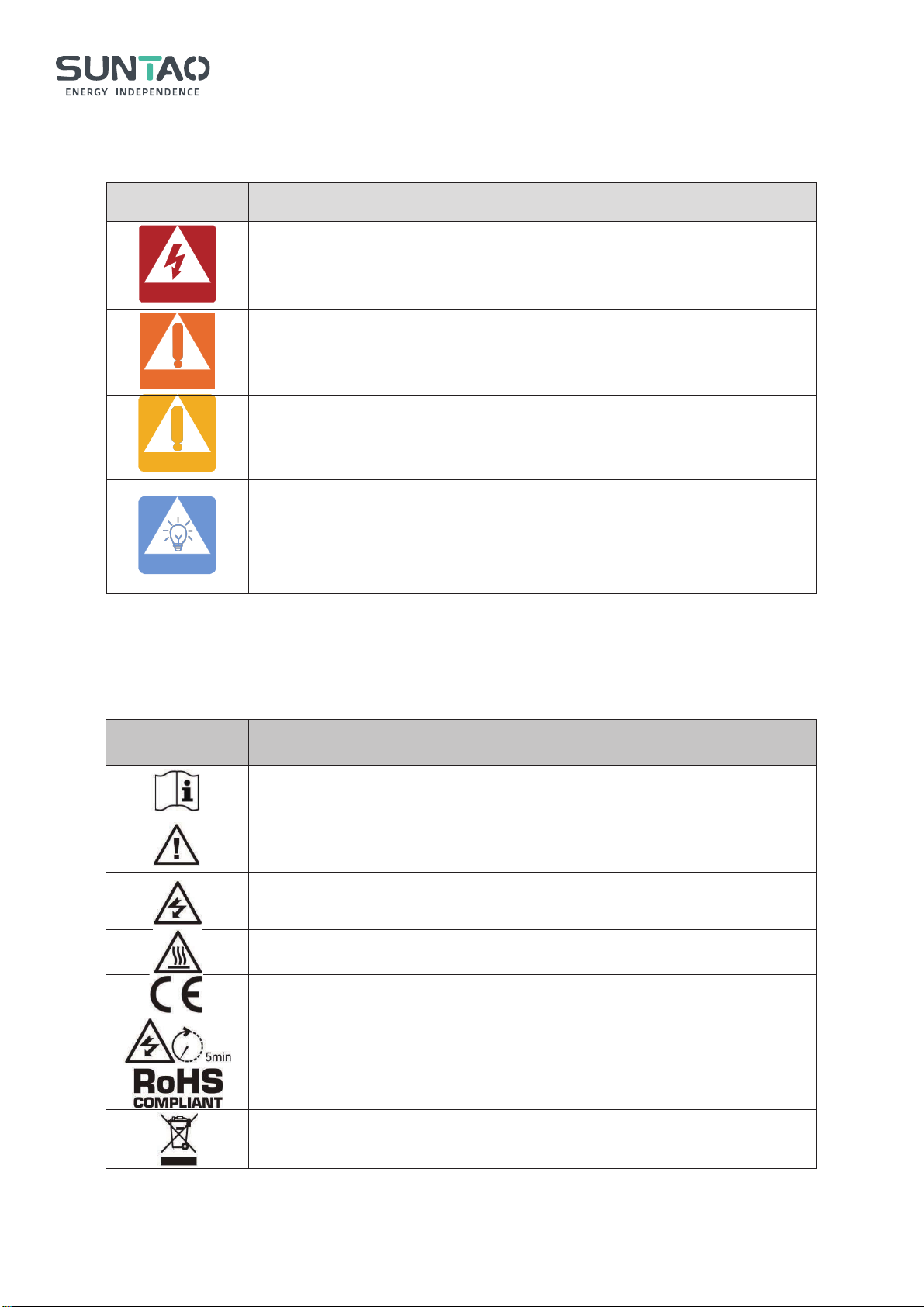
General Safety 2.1.1Important Notice Before installing, operating and maintaining the device, please read this Manual first and follow the symbols
on the device and all the safety precautions in this Manual.
The matters indicated with "DANGER", "CAUTION", "ATTENTION" and "NOTICE" in this Manual do not
represent all the safety matters to be observed, but are only the supplements to all the safety precautions. The
Company will not be liable for any violation of general safety operating requirements, or any violation of safety
standards for the design, production and use of the device. The device must be used in an environment that
meets the requirements of the design specifications. Otherwise, the device may fail, and the abnormal device
function or component damage, personal safety accident, and property loss arising from this are not covered
within the quality assurance scope of the device. When installing, operating, and maintaining the device, the
local laws, regulations, and codes shall be followed. The safety precautions in this Manual are only supplements
to local laws, regulations, and codes. The Company shall not be liable for any of the following circumstances.
The device is not run under the conditions of operating described in this Manual.
The installation and operating environment is beyond the requirements of relevant international or
national standards.
The product is disassembled or changed, or the software code is modified without authorization.
The operation instructions and safety warnings related with the product and in the documents are not
followed.
Damage of the device is caused by abnormal natural environment (force majeure, such as earthquake, fire,
and storm).
Transportation damage is caused during customer's own transportation.
The storage condition does not meet the requirements of the product related documents and causes
damage.
2.1.2General Requirements
DANGER!
Operating when the power is on is strictly prohibited during installation.
DANGER!
It is strictly prohibited to install, use, and operate any outdoor equipment or cables (including but
not limited to transporting equipment, operating equipment and cables, plugging and removing
signal ports connected to the outdoor, working at altitude, and outdoor installation) in severe
weather, such as thunder, rain, snow, and gale level 6.
04

DANGER!
In case of any fire, evacuate the building or equipment area and press the fire alarm bell or dial
the fire call. Under any circumstances, re-entry into a burning building is strictly prohibited.
CAUTION
Under no circumstances should the structure and installation sequence of the device be changed
without the manufacturer's permission.
CAUTION
The battery terminal components shall not be affected during transportation. And, the battery
terminal bolts shall not be lifted or transported.
ATTENTION
It is strictly prohibited to alter, damage or block the marks and nameplates on the device.
ATTENTION
The composition and working principle of the entire photovoltaic power generation system, as well
as the relevant standards of the country/region where the project is located shall be known fully.
NOTICE
After the device is installed, the empty packing materials, such as cartons, foam, plastics, and
cable ties, shall be removed from the device area.
2.1.3Personnel Safety
When operating the device, appropriate personal protective equipment shall be worn. If any fault that may
lead to personal injury or damage of the device is found, immediately terminate the operation, report to
the responsible person, and take effective protective measures.
Before using any tools, learn the correct method of using the tool to avoid injuries and damage of the
device.
When the device is running, the temperature of the case is high, which may cause burns. Therefore, do
not touch the case.
In order to ensure personal safety and normal use, reliable grounding should be carried out before use.
Do not open or damage the battery. The electrolyte released is harmful to skin and eyes, so avoid touch it.
Do not place irrelevant items on the top of the device or insert them into any part of the device.
Do not place flammable items around the device.
Never place the battery in the fire to avoid explosion and prevent the personal safety from being
endangered.
Do not place the battery module in water or other liquids.
05

Do not short-circuit the battery terminals, because short-circuiting of the battery may causecombustion.
The battery may pose a risk of causing electric shocks and large short-circuit currents. When using the
battery, the following precautions should be paid attention to:
a)
The metal objects, such as watch and rings, shall beremoved.
b)
Tools with insulated handles should be used.
c)
Rubber gloves and shoes should be worn.
d)
The charging power supply shall be disconnected before connecting or disconnecting terminals of
the battery.
e)
Check whether the battery is accidentally grounded. If the battery is accidentally grounded, remove
the power supply from the ground.
Do not clean the internal and external electrical components of the cabinet with water or detergent.
Do not stand, lean or sit on the device.
Do not damage any modules of the device.
2.2
Personnel Requirements
The personnel in charge of installation and maintenance must be strictly trained to understand all safety
precautions and master proper operation methods.
Only qualified professionals or trained personnel are allowed to install, operate and maintain the device.
The personnel who operate the device, including the operators, trained personnel and professionals,
must have special operation qualifications required by the local country, such as high voltage operation,
working high above the ground, and special equipment operation qualification.
The replacement of device or components (including software) must be carried out by professionals or
authorized personnel.
2.3
Electrical Safety 2.3.1General Requirements Before carrying out electrical connections, ensure that the device is not damaged, or an electric shock or fire may occur. Never install or remove any power cables when the power is on. The electric arcs or sparks may be generated at the moment when the power cable contacts with the conductor, which may cause fire or personal injuries.
DANGER!
DANGER!
06

All the electrical connections must meet the electrical standards of the country/region where the project is
located.
The cables prepared by users themselves shall comply with local laws and regulations.
Special insulating tools should be used in high-voltage operations.
Before connecting the power cord, ensure that the label identification on the power cord is correct.
Operations on the device are allowed only five minutes after the device is completely powered off.
The insulation layer of the cable may be aged or damaged when the cable is used in a high temperature
environment. Therefore, the distance between the cable and the heat source must be at least 30mm.
Cables of the same type should be bundled together. Whereas, the cables of different types should be
routed at least 30mm apart, and shall not be wrapped together or crossed.
2.3.2Grounding Requirements
When installing the device to be grounded, the protective grounding wire must be installed first; when
removing the device, the protective grounding wire must be removed at last.
It is forbidden to destroy the grounding conductor.
It is forbidden to operate the device without a grounding conductor installed.
The device shall be permanently connected to the protective grounding wire. Before operating the device,
electrical connection of the device shall be checked to ensure that the device is reliably grounded.
2.4
Installation Environment Requirements
This product is for indoor use only, and is strictly prohibited to be used in outdoorenvironment.
Do not install or use this product in an environment where the temperature is lower than -10 or higher
than 50
It should be installed in a dry and well-ventilated environment to ensure good heat dissipation
performance.
The product can be installed at a maximum altitude of 2,000m.
The installation position should be away from the fire source.
The product should be installed and used away from children and animals.
The installation position should be far away from water sources, such as faucets, sewer pipes, and
sprinklers, to avoid entering of water.
The device should be placed on a firm and flat supporting surface.
Do not place any inflammable or explosive items around the device.
When the device is running, do not block the ventilation vent or heat dissipation system to prevent fire
caused by high temperature.
07

The operation and service life of the energy storage is related to the operating temperature. The energy storage should be installed at a temperature equal to or better than the ambient temperature.
3
Product Introduction
3.1
Brief Introduction to Product All-In-One Energy Storage System is a new generation of household energy storage system with two output
specifications of 220V and 110V, which can meet the diversified needs of global users. The All-In-One Energy
Storage System energy storage system adopts a modular design, including power modules and battery
expansion modules, so it can be easily combined into a system of any capacity required by the user.
The lithium iron phosphate batteries with high performance and long service life are used in the energy
storage module. Meanwhile, the modular structure design is adopted. Each energy storage module is internally
integrated with the intelligent BMS system, which can be easily expanded and can be combined into 20Kwh
battery pack at most.
The brand new topological circuit design is adopted in the power module, which can realize the energy
exchange between photovoltaic, mains, battery and loads, and has the function of photovoltaic and mains
charging. The photovoltaic charging module adopts the latest optimized MPPT tracking technology, which can
quickly track the maximum power point of the photovoltaic array in any environment, and obtain the maximum
energy of the solar panel in real time. In addition, MPPT has a wide voltage range. The advanced control
algorithm is adopted in the mains charging module to realize the fully-digital double closed-loop control of
voltage and current, so the control precision is high and the volume is small. The AC voltage input range is wide,
and the input/output protection functions are complete, which can realize the stable and reliable charging and
protection of batteries. The inverter module is based on the full-digital intelligent design, adopts the advanced
SPWM technology, outputs pure sine wave, converts direct current into alternating current, and is applicable for
household appliances, power tools and other AC loads.
The typical topological diagram for application of the system is as follows:
CAUTION
08

3.2
System Specifications
Structure
Parameters
1+3
1+4
1+5
1+6
Type
SA MPI 5kW/15kWh
SA MPI 5kW/20kWh
SA MPI 5kW/25kWh
SA MPI 5kW/30kWh
Battery
3
4
5
6
Off-grid Inverter
Rated Output Power
SKW
Maximum Peak Power
l0KVA
Power Factor
1
Rated Output Voltage (Vac)
230Vac 120Vac
Frequency
S0Hz
60Hz
Auto Switch Period
<lSms
Maximum AC Charge Power
3150W
2100W
AC Charging Current Range
0~60A
0~40A
Input Voltage Range
90~280Vac
90~140Vac
09

Structure
Parameters
Type
VA MPI 5kW/5kWh VA MPI 5kW/10kWh
Battery
2
Off-grid Inverter
Rated Output Power
5KW
Maximum Peak Power
10KVA
Power Factor
1
Rated Output Voltage (Vac)
230Vac
120Vac
Frequency
50Hz
60Hz
Auto Switch Period
<l0ms
Rated Output Power
SKW
Maximum Output Current
30A
Output Frequency
S0Hz
60Hz
Overload Current
35A SSA
Solar Charge Type
MPPT
Maximum PV Array Power
SKW
PV Charging Current Range
0~80A
MPPT Voltage Range
120~450V
Battery
Capacity
15.36kWh
20.48kWh
25.60kWh
30.72kWh
Battery Voltage/Range
46.7-57V
Maximum Charging Power
5kw
Maximum Charging Purrent
60A
Maximum Discharging Power
5kw
Maximum Discharging Current
100A
Other Information
Dimension Lx DxH
600*540*740mm
600*540*920mm
600*540*1100mm
600*540*1280mm
Weight
161kg
204kg
247kg
290kg
Operation Humidity
5%~85%
Operating Temperature Range
-15°C ~ SS°C
Nominal Operation Altitude
< 2000m
Ingress Protection Rating
IP20
10

Maximum AC Charge Power
3150W
2100W
AC Charging Current Range
0~60A
0~40A
Input Voltage Range
90~280Vac
90~140Vac
Rated Output Power
5KW
Maximum Output Current
30A
S0A
Output Frequency
S0Hz
60Hz
Overload Current
35A
SSA
Solar Charge Type
MPPT
Maximum PV Array Power
SKW
PV Charging Current Range
0~80A
MPPT Voltage Range
120~450V
Battery
Capacity
5.12kWh
10.24kWh
Battery Voltage/Range
46-57V
Maximum Charging Power
5ooow
Maximum Charging Purrent
60A
Maximum Discharging Power
5ooow
Maximum Discharging Current
100A
Other Information
Dimension Lx DxH
600*185*1100mm
600*185*1600mm
Weight
80kg
125kg
Operation Humidity
5%~85%
Operating Temperature Range
-15°C ~ SS°C
Nominal Operation Altitude
< 2000m
Ingress Protection Rating
IP20
Noise
<60dB
3.3
Description of Energy Storage Capacity All-In-One Energy Storage System series energy storage system supports the capacity expansion with up to
four energy storage modules.
11

3.4
Appearance Description 3.4.1Dimentions Inverter dimensions(L*W*H):555*130*500mm
Battery dimensions(L*W*H):555*130*600mm
Base dimensions(L*W*H):635*130*80mm
3.4.2Power Conversion System Module The power of power conversion system is 5.0KW.
12

Picture of real products˖
13

3.4.3Energy Storage Battery Module Communication Interface Definition for RPT Lithium Battery
PIN foot
CAN-RJ45
PIN1
NC
PIN2
NC
PIN3
NC
PIN4
CANH
PIN5
CANL
PIN6
NC
PIN7
GND
PIN8
NC
PIN foot
RS485-RJ45
PIN1
RS485-B
PIN2
RS485-A
PIN3
GND
PIN4
NC
PIN5
NC
PIN6
GND
PIN7
RS485-A
PIN8
RS485-B
14

Inverter Protocol Selection
The default setting protocol for the battery is PYLON. If communicate with other inverters, the
corresponding inverter protocol needs to be selected, and the operation process is as follows:
1.Tools: computer, USB to 232 wiring harness, monitoring software
2.Operating steps:
A.Connect the computer and battery using a USB to 232 wire harness, plug the USB port into the USB port
of the computer, and connect the other end of the wiring harness to the battery RS232 interface.
B.Download the software compression package to the computer as follows:
C.Unzip the compressed package to the current folder as follows:
D.Open the extracted folder and select the application in the folder as follows:
E.Double click on the above icon to enter the monitoring interface as follows:
15

F.After entering the monitoring interface, click on the “Open” and then click on “Try Connect”. When battery
communication succeeded, the real-time information will be displayed on the left side of monitoring interface,
and the “Password”will display green.
G.After communication is normal, enter the password 123456 in the password status bar in the bottom right
corner. After entering it correctly, the status bar will display green.
H.Click "System Config" as follows
I.Click "Read" on the middle (inverter protocol) section on the right side of the display interface to check
16

whether the battery matches the inverter or not. If it does not match, click on the CAN protocol or 485 protocol,
and select the protocol that matches the inverter as follows:
J.After selecting the protocol, click the "Write" button. If the write fails, it indicates that the BMS does not
include this inverter protocol. It is necessary to upgrade the program and select the protocol again; If the write is
successful, please click “Read” again to see if the protocol is actually selected
4
Application Scenarios The lithium iron phosphate batteries with high performance and long service life are used in the energy
storage module. Meanwhile, the modular structure design is adopted. Each energy storage module is internally
integrated with the intelligent BMS system, which can be easily expanded and can be combined into 20Kwh
battery pack at most.
The battery storage can be combined with SRNE brand inverter to form an off-grid photovoltaic system,
which can solve the problem of electricity consumption in areas without electricity.
4.1
Application Scenarios 4.1.1Application Scenarios with Only Mains Power but No Photovoltaic When the mains is normal, it charges the battery and supplies power to the loads.
When the mains is disconnected or stops working, the battery supplies power to the load through the power
17

module.
4.1.2Application Scenarios with Only Photovoltaic but No Mains Power During the day, the photovoltaic directly supplies power to the loads while charging the battery.
At night, the battery supplies power to the loads through the power module.
4.1.3Complete Application Scenarios 18

During the day, the mains and photovoltaic simultaneously charge the battery and supply power to the loads.
At night, the mains supplies power to the loads, and continues to charge the battery, if the battery is not fully
charged.
If the mains is disconnected, the battery supplies power to the loads.
19

4.2
Load Working Mode Load working mode Inverter setting Description
PV priority mode
PV 1ST
switching to the Mains when the PV fails or the battery is lower
than the set value of parameter
Mains priority mode
(Default )
AC 1ST
Mains priority mode, switching to inverter only when the mains
fails.When the battery is full, the load power is supplied by the
hybrid of PV and the utility.
Battery priority mode
BT 1ST
switching to the mains only when the battery is under voltage or
lower than the set value of parameter
5
System Installation
5.1
Inspections before Installation Inspection of outer package Before opening outer package of the energy storage, check if there is any visible damage on the outer
package, such as holes, cracks or other signs of possible internal damage, and check the type of energy storage.
If there is any abnormality on the package or model of the energy storage is inconsistent, do not open it and
contact us as soon as possible.
Inspection of deliverables After opening outer package of the energy storage, check if the deliverable is complete and whether there is
any visible external damage. If any items are missing or damaged, please contact us.
NO.
Picture Item Quantity Specification Source
1
Inverter
1
5.0kW/48V,110V/220V
Inverter
Package
2
Base
1
680*184*80mm
Inverter
Package
20
This manual suits for next models
5
Table of contents
Popular Storage manuals by other brands

Synology
Synology FlashStation FS1018 Hardware installation guide

Buffalo
Buffalo MiniStation HD-PCTU3 user manual

Macpower & Tytech
Macpower & Tytech M9 - NDAS user manual

Rorke Data
Rorke Data Galaxy RAIDGHDX2-2130-16iSCSI Installation and hardware reference manual

Seagate
Seagate USB 2.0 120GB manual

Buffalo
Buffalo TS-RHTGL-R5 user manual

Seagate
Seagate SKYHAWKLITE ST2000VX007 product manual

KI
KI RUCKUS TOTE STORAGE Assembly instructions

Microdia
Microdia SDHC operating manual

Huawei
Huawei FusionModule1000A40 ICT Solution Initial Configuration Parameter Manual

Apacer Technology
Apacer Technology AH790 user manual

Keter
Keter DENALI 100 US GAL 380L user manual