SunWare FOX-260 User manual

FOX-260
Solar Charge Regulator
Solar Laderegler Solar Charge Regulator
Régulateur de charge solaire Regolatore di carica solarea
Installation
| DE | GB | FR | IT |
Internet: http://www.sunware.de
S O L AR T E C H N I K GmbH & Co KG
PHOT OVO LTAIK
MA D E IN G E R MA NY
Printed: 20November 12
Doc.No.: {BDAEB717-47E2-4597-885B-BD056658606A}

B1 B2
+
--
+
-
+
-
+
FOX-260
Taste
Escape/undo
Übersicht
0|
Verbraucher Anschluss (Output)
Batterie 1 Anschluss (Wohnbereich)
Anschluss für Solarmodule
Packungsinhalt: 1 x FOX-260
2 x Befestigungsschrauben
1 x Bedienungsanleitung
1 x Abdeckkappe (aufgesteckt)
1
Befestigungslöcher Display
Taste
Bestätigen
Tasten
Parameter
Einstellung
Tasten
Menue Navigation
[ ! ]
Wichtige Hinweise
1|
Bitte lesen Sie Inbetriebnahme des Ladereglers dieseVOR
Bedienungsanleitung sorgfältig durch!
Wichtige Hinweise:
Es dürfen nur Solarmodule als Spannungsquelle angeschlossen·
werden - keine Windgeneratoren oder andere Ladegeräte.
Die Leerlaufspannung Uoc des Solarsystems darf nicht
·50V
überschreiten, ansonsten kann der Regler dauerhaft beschädigt
werden (siehe Typenschild des Moduls).
Eine defekte oder vollständig entladene Batterie (U < 8,5 V)
·
kann aus Sicherheitsgründen mit dem FOX-260 nicht wieder
aufgeladen werden.
Alle Vorsichtsmaßnahmen für Arbeiten mit Batterien und Leistungs-
·
elektronik müssen eingehalten werden.
Alle Batterieleitungen zum Regler müssen entsprechend dem
·
verwendeten Leitungsquerschnitt abgesichert sein, diese
Komponenten gehören nicht zum Lieferumfang.
Der Regler darf nicht mit Wasser oder kondensierender Feuchtig-
·
keit in Kontakt kommen und ist vor direkter Sonneneinstrahlung
zu schützen.
An den FOX-260 dürfen keine Nickel-Cadmium-, Nickel-
·
Metallhydrid-, Litium-Ionen-, Lithium-Polymer-Akkus angeschossen
werden.
Der Regler darf nur in geschlossen Räumen verwendet werden.
·
2
DE |GB|FR|IT

FOX-260
Wir freuen uns, dass Sie sich für den FOX-260 mit modernster
Regeltechnik und beleuchtetem Display entschieden haben.
Den Regler kennzeichnet die einfache Bedienbarkeit und das elegante
Design. Die speziell entwickelten Ladekennlinien werden das
Maximum an Leistung aus Ihren Solarmodulen herausholen und
vollständig in der Batterie speichern. Wir wünschen Ihnen viel Freude
mit Ihrer Solaranlage.
Der FOX-260 ist ein Solarladeregler für Modulströme bis zu 20 A,
geeignet für AGM-, GEL- und Blei-Säure-Batterien. Verbraucher können
bis zu einem Stromverbrauch von maximal 20 A angeschlossen
werden. Der adaptive Tiefentladeschutz überwacht und schützt die
Batterie vor schädlicher Tiefentladung, alternativ kann die Nachtlicht-
funktion genutzt werden. Bei der Nachtlichtfunktion wird in der Zeit, in
der die Module keinen Ladestrom liefern (also wenn es dunkel ist), ein
Verbraucher eingeschaltet. Ideal zum Betreiben eines Orientierungs-
lichts oder kleiner Beleuchtung, um Einbrüche zu verhindern.
Die optimierte Ladekennlinie erzielt in Kombination mit der Hardware
PWM-Regelung eine deutlich schnellere und schonendere Ladung der
Batterie, gefährliche Gasung bzw. Überladung werden sicher
verhindert.
Der Regler erkennt beim Einschaltvorgang vollautomatisch, ob ein
12 V- oder 24 V-Batteriesystem angeschlossen ist. Die aktive
Rückstromsperre garantiert den Rückstromschutz und ermöglicht
einen extrem geringen Spannungsabfall zwischen Modul und Batterie.
Der Laderegler kann parallel zu anderen Ladegeräten betrieben
werden (wie Lichtmaschine, Generator, Brennstoffzelle).
An den Regler können Module beliebiger Hersteller angeschlossen
werden. Die Leerlaufspannung der Solarmodule bzw. des
Solarsystems bei Serienschaltung muss kleiner 50 V betragen.
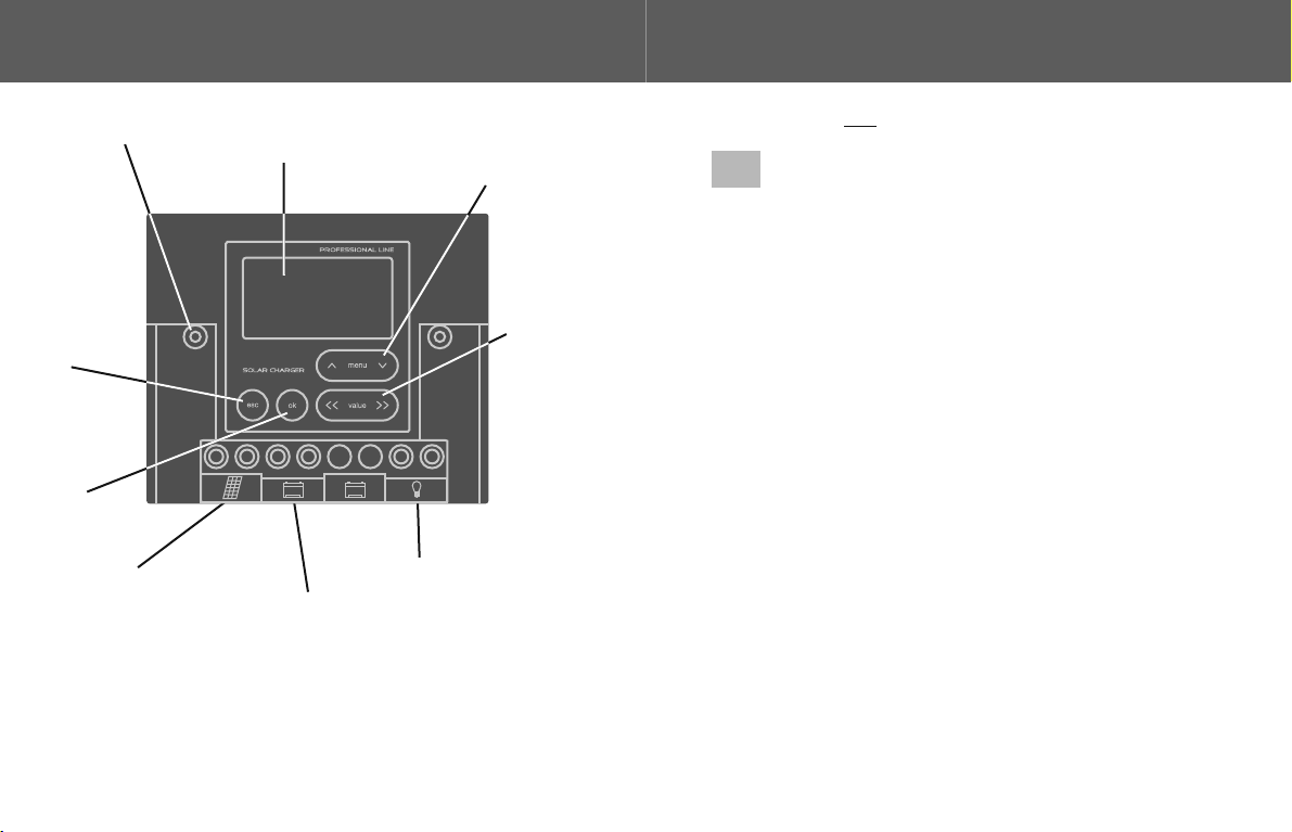
Beschreibung
2|
3
Beim FOX-260 sind die Klemmen B1(-) und Output über die Minus-
Leiterbahn direkt miteinander verbunden.
Die Batterieleitung muß unmittelbar an den Pluspolen der Batterien mit
einer Sicherung von 20A versehen werden.
Durch die Tastatur können verschiedene Darstellungen im Display
gewählt und diverse Grundparameter des Reglers verändert und
gespeichert werden.
Die aktuellen Batteriespannungen können zusätzlich auch als Grafik in
Balkenform dargestellt werden.
Beschreibung
2|
4
DE |GB|FR|IT

Anschluss
3|
Montage
Zur besseren Wärmeabfuhr muss der Regler auf einem senkrechten,
nicht oder nur schwer brennbaren Untergrund mit den beiden
beiliegenden Schrauben montiert werden.
Weiterhin muss der Bauraum ober- und unterhalb des Reglers für
mindestens eine Reglerhöhe freigehalten werden um den erforder-
lichen Kühlluftstrom zu gewährleisten.
Anschluss:
Achtung: Im Betrieb kann der Kühlkörper heiß werden. Klemmen
Sie in beliebiger Reihenfolge die Kabel wie unten gezeigt an.
Polarität beachten!
5
[ ! ]
B1 B2
+
--
+
-
+
-
+
+
-
+
-
+
-
1
Solarmodul Batterie 1 Verbraucher
Anschluss
3|
6
Sobald die Batterie 1 angeklemmt wird startet der Regler. Während der
Startphase führt der Regler einen Selbsttest durch und erkennt die
Systemspannung (beachten Sie das Display).
Überprüfen Sie zum Abschluss der Installation bitte noch einmal alle
elektrischen Verbindungen auf festen Sitz.
Achtung: Dieser Punkt ist unbedingt zu beachten, da sich
lose Klemmverbindungen unzulässig stark erwärmen
können und somit ein potentielles Sicherheitsrisiko
darstellen.
Während der Startphase zeigt der Regler im Display die Versions-Nr.
der Software und die als Systemspannung erkannte Batteriespannung
an.
Wollen Sie den Reset-Vorgang wiederholen, müssen Sie nur die
Leitung von "B1+" für mindestens 10sek. von der Klemme entfernen.
Der Strom für die Verbraucher an der Output Klemme wird immer von
Batterie 1 entnommen.
Wichtiger Hinweis:
Die Minuspole der Solarmodule dürfen nicht mit der Fahrzeug-
masse verbunden werden, ansonsten wird der Solar-Laderegler
überbrückt und somit unwirksam. In der Folge kann dies zu einer
unkontrollierten Überladung der Batterien führen!
DE |GB|FR|IT
[ ! ]
[ ! ]

Schließen Sie den FOX-260 an, können Sie komfortabel alle
Spannungen, Ströme, Ladezustände auf dem großen und beleuchteten
Display und teils als Grafik ablesen. Darüber hinaus können Sie
zahlreiche Parameter verändern wie z. B. Lade-Endspannungen,
maximale Entladetiefe und vieles mehr. Nachdem Sie den Luxus einmal
kennen gelernt haben, wollen Sie auf den FOX-260 nicht mehr
verzichten.
Die Bedienung des FOX-260 ist sehr einfach, da alle Menüs nach dem
gleichen Prinzip aufgebaut sind:
Mit den Pfeiltasten und werden die einzelnen Anzeigemasken
aufgerufen.
Bei den Anzeigemasken wird zwischen einer reinen undDatenausgabe
einer unterschieden:Parameteranzeige
1.) Datenausgaben:
Bei den Anzeigemasken für die Datenausgaben haben die Tasten
keine Funktion. Mit der -Taste wird direkt wieder
die Standardanzeige angezeigt.
2.) Parameteranzeige:
Bei den Anzeigemasken für die Parameteranzeige sind die Tasten
aktiviert. Sobald man oder betätigt, wird die
vorherige oder nächste mögliche Option für diesen Parameter
angezeigt. Erst mit Betätigen der Taste werden die Daten ge-
speichert. Während des Speichervorgangs wird im Display "saving..."
ausgegeben, am Ende der erfolgreichen Speicherung “saved".
7
FOX-260 Funktionen
4|
Mit der Taste wird die Eingabe rückgängig gemacht und die
ursprünglichen Daten werden wieder hergestellt (Undo-Funktion). Bei
nochmaligem Betätigen der -Taste springt die Anzeige dann zurück
in die Standardanzeige.
Werden für 15 Sekunden keine Eingaben in einer Parameteranzeige
getätigt, springt die Anzeige automatisch wieder zurück auf das
Standard-Display.
Wird eine Anzeige der Datenausgabe für länger als 20 min. angezeigt,
legt der Regler diese als Standard-Display fest. Zu dieser Anzeige
springt der Regler zurück, wenn die -Taste betätigt wurde.
FOX-260 Funktionen
4|
8
DE |GB|FR|IT

Display-Funktionen FOX-260
5|
Display-Anzeigen:Pos. Bedeutung:
9
0Batt. 1: akt. Spannung Batt. 1
I Charge: akt. Ladestrom
I Solar: akt. Modulstrom
I Out: akt. Verbrauchsstrom
" " Batterie, die momentan
->
geladen wird
-> Battery 1 = 12.9 V
ICharge = 0.0 A
ISolar = 0.0 A
IO = 0.0 Aut
0
1
-> Battery 1
0 % 50 % 100 %
""-> Batterie, die momentan
geladen wird
Balkendiagramm: Ladezustand
1
2
Nutzungsart der
Output-Klemme
Mode Output
AUTO LAMP ON OFF
<< >>
2
3
Kapazitätsnutzung
der Batterie 1
Capacity Usage
80 %
<< >>
3
Display-Funktionen FOX-260
5|
10
DE |GB|FR|IT
Display-Anzeigen:Pos. Bedeutung:
5
Kontrasteinstellung des
Displays
Contrast
50 %
<< >>
5
Battery 1 Type
AGM GEL ACID
<< >>
4
Batterietyp B 1
4

Display-Funktionen FOX-260
5|
11
Bedeutung der Datenausgabe:
Battery 1 = aktuelle Batteriespannung an Klemme B1
ICharge = aktueller Ladestrom
ISolar = aktuell von den Modulen erzeugter Strom
(dieser Wert kann größer als ICharge sein, wenn der
Laderegler den Ladestrom reduziert um ein Überladen
der Batterie zu verhindern)
IOut = aktueller Verbrauchsstrom
Bedeutung der Parameteranzeigen:
Mode Output:
Setzt die Nutzungsart der Output Klemme. Es stehen 4 Funktionen zur
Verfügung:
!AUTO
!LAMP
!ON
!OFF
Bei schaltet der Regler die Verbraucher automatisch aus, fallsAUTO
die Batterie zu stark entladen ist. Steigt die Batteriespannung wieder
an, werden die Verbraucher automatisch wieder eingeschaltet.
Bei geht der Regler davon aus, dass an der Output-KlemmeLAMP
eine kleine Leuchte (z.B. als Orientierungslicht) angeschlossen ist.
Diese Leuchte wird dann jede Nacht, sobald das Modul keinen
Ladestrom mehr liefert, eingeschaltet und bei Tagesanbruch wieder
ausgeschaltet. Der Tiefentladeschutz ist weiterhin aktiv.
Bei und verbleibt der Status der Klemme dauerhaft in derON OFF
gewählten Position. Bei liegt an der Klemme die Spannung derON
Batterie 1 an.
Display-Funktionen FOX-260
5|
DE |GB|FR|IT
12
ACHTUNG: ONMit der Stellung ist jeglicher Schutz vor
Tiefentladung der Batterie 1 deaktiviert.
Capacity Usage:
Die Kapazitätsnutzung der Batterie 1 kann in 5 % Schritten eingestellt
werden. Ein Wert von 80 % bedeutet, dass die an der Output-Klemme
angeschlossenen Verbraucher erst ausgeschaltet werden, wenn nur
noch 20 % Restkapazität in der Batterie 1 vorhanden ist.
Ein größerer Wert als 80 % kann nicht eingestellt werden.
Wird die Output-Funktion verändert, wird die Kapazitätsnutzung auf
den für diese Funktion definierten Standardwert zurückgesetzt.
Standardwerte:
Funktion: = 80 % (10,8 V)AUTO
Funktion: = 50 % (11,3 V)LAMP
Bei der Funktion und erfolgt keine Änderung.ON OFF
Battery Type:
Zur optimalen Anpassung der Ladekennlinie und Ladeendspannungen
an den angeschlossenen Batterie-Typ kann dieser hiermit festgelegt
werden.
Es bestehen folgende Wahlmöglichkeiten:
!AGM (Ladeschlußspannung 14,2 V)
!Gel (Ladeschlußspannung 14,3 V)
!Blei-Säure (Ladeschlußspannung 14,4 V)
Standardeinstellung: AGM
Contrast:
Zur besseren Lesbarkeit des Displays unter verschiedenen
Beleuchtungsbedingungen kann der Kontrast eingestellt werden.
[ ! ]

13
Allgemeine technische Daten:
Merkmal Wert/Einheit
Systemspannung 12V / 24V automatisch
- keine Erkennung < 6V
- Erkennung 12 V 6V - 17,0V
- Erkennung 24 V > 17,0V
Betriebsspannung 8,5V ... 35V
Überladeschutz max. 20A bei 25°C
Temp. Kompensation -20mV/°K @12V, -40mV/°K@24V
Regelfrequenz 244Hz
max. Klemmenspannung 50V (Uoc auf Modullabel)
Tiefentladeschutz max. 20A bei 25°C
- Ein-/Ausschaltverzögerung 1min
Nachtlichtfunktion max. 20A bei 25°C
- einschalten wenn kein Ladestrom
- ausschalten wenn Ladestrom fließt
- Ein-/ Ausschaltverzögerung 10 min
Display beleuchtetes grafisches LCD
128 x 64 Pixel
Anschlussklemmen VA Schraube, max. 16mm²
Sicherungen an B1, B2 25A, intern eingelötet
Eigenstrombedarf (beleuchtet) 7,0 (18,0) mA
Spannungsverlust 0,0 - 0,27V (bei 0 - 20A)
Umgebungsbedingungen -25°C ... + 50°C, nicht tauend
Lagerbedingungen -25°C ... + 80°C
Batterieumschalter Relais, bistabil
Schutzart IP 22
Gewicht 300g
6| Technische Daten FOX-260
14
DE |GB|FR|IT
Hinweise zu Garantieleistungen
Für das an Sie gelieferte Gerät gemäß Rechnung gewährt der
Hersteller ab Kaufdatum eine 24-monatige Garantie. Zum Nachweis
der Garantie gilt nur der Kaufbeleg. Alle innerhalb der Garantie
auftretenden Funktionsfehler, die nachweisbar trotz sachgemäßem
Gebrauch entstanden sind, beheben wir bis 24 Monate nach
Kaufdatum kostenlos. Zur Durchführung der Garantiearbeiten muss
das defekte Gerät für den Hersteller kostenlos an das Werk geschickt
werden. Es bleibt unserer Wahl überlassen, ob wir die defekten Teile
reparieren oder austauschen. Ausgetauschte Teile gehen in unser
Eigentum über. Die Kosten für den Rückversand werden vom Kunden
getragen. Durch die Erbringung von Garantieleistungen tritt keine
Verlängerung der ab Kaufdatum eingeräumten Garantiezeit ein. Die
Garantiezeit für Teile, die im Rahmen der Garantie ausgetauscht
werden, läuft mit Ende der Garantiezeit ab.
Von der Garantie ausgenommen sind:
- Schäden, die auf Nichteinhaltung der Hinweise der
Bedienungsanleitung zurückzuführen sind.
- Schäden, durch Verpolung, Überstrom, Überspannung und
Blitzschlag.
- Geräte, die von Kundenseite geöffnet wurden.
Durch die Herstellergarantie wird die gesetzliche Gewährleistungs-
pflicht nicht eingeschränkt.
Das Produkt entspricht den Bestimmungen der EMV-Richtline
89/336/EWG. Die vollständige Konformitätserklärung ist einsehbar
unter: www.sunware.de
Hersteller:
SunWare GmbH & Co KG
Düsseldorfer Str. 80
D-47239 Duisburg www.sunware.de
Gewährleistung
7|
Irrtümer und Änderungen vorbehalten.

15
Abmessungen
8|
inches
mm
B1 B2
+
--
+
-
+
-
+
FOX-260
16
0|
Mounting holes
Consumer connection (output)
Battery 1 connection (living area)
Connection for solar modules
Package contents: 1 x FOX-260
2 x mounting screws
1 x operating instruction
1 x cover for connecting terminals (plugged)
Display
Key
Escape/undo
Key
Confirm
Keys
Parameter
setting
Keys
Menu navigation
DE | |FR|ITGB
Overview

17
[ ! ]
Important note
1|
Please carefully read these operating instructions to the firstprior
operation of the charge controller!
Important notes:
Only connect solar modules as voltage sources – do not connect·
any wind generators or other charging devices.
The off-load voltage Uoc of the solar system must not exceed 50V;
·
otherwise, the controller may be permanently damaged (see type
plate of the module).
A faulty or totally discharged battery (U < 8,5 V) must not be
·
recharged using the FOX-260 due to safety reasons.
All precautions regarding work with batteries and power electronics
·
must be observed.
All battery cables to the controller must be fuse-protected in
·
accordance with to the used wire cross section, these components
are not included in the scope of supply.
The controller must not get in contact with water or condensing
·
humidity and is to be protected against direct solar radiation.
·No nickel-cadmium, nickel-metallic hydride, lithium-ion, lithium-
polymer batteries must be connected to the FOX-260.
Only use the controller in closed rooms.
·
18
DE | |FR|ITGB
FOX-260
We are pleased that you decided on the FOX-260 with cutting edge
control engineering and illuminated display.
The controller is characterized by its ease of operation and elegant
design. The specifically developed charge characteristic curves will
extract the maximum power from your solar modules and store it
completely in the batteries. We hope you will enjoy your solar
installation.
The FOX-260 is a solar charge controller for modulated currents up to
20 A, suitable for AGM, gel and lead acid batteries. Consumers can be
connected up to a current consumption of 20 A maximum.
The adaptive total discharge protection monitors and protects the
battery against damaging total discharge, and alternatively the
nightlight function can be used. When using the nightlight function, a
consumer will be switched on during the time the modules do not
supply charge current (i.e. when it is dark). Ideal for the operation of an
orientation light or small lights for the prevention of break-ins.
The optimised charge characteristic curve in combination with the
hardware PWM control achieves a distinctly faster and gentler
charging of the battery; hazardous gassing or overcharging are safely
prevented.
On switching on, the controller recognises fully automatically whether
a 12 V or 24 V battery system is connected. The active battery cut-out
ensures the protection against reverse current and allows for an
extremely low voltage drop between module and battery.
Description
2|

19
The charge controller can be operated in parallel to other charging
devices (such as alternators, generators, fuel cells). Modules of all
manufacturers can be connected to the controller.
With series connection, the off-load voltage of the solar modules and/or
the solar system must be smaller than 50 V.
In the case of the FOX-260 the terminals B1(-) and Output are directly
connected with each other via the negative conductor.
The battery line must be provided with a 20A fuse directly at the plus
poles of the batteries.
By means of the keyboard, different presentations can be selected in
the display and various basic parameters of the controller may be
changed and stored.
Current battery voltages may also be additionally presented as a
graphic in bar form.
Description
2|
20
DE | |FR|ITGB
Connection
3|
Installation
For better heat dissipation, the controller must be mounted with the
two enclosed screws onto a vertical, fireproof or flame-retardant base.
Furthermore, the installation space above and below the controller
must be kept free for at least one controller height to ensure the
required cooling air flow.
Connection
ttention: During operation the cooling element can become hot.A
Connect the cables in random order, as described below.
Observe the polarity!
[ ! ]
B1 B2
+
--
+
-
+
-
+
+
-
+
-
+
-
1
Solar module Battery 1 Consumer

21
Connection
3|
When battery 1 is connected, the controller will start. During the start
phase, the controller carries out a self-test and detects the system
voltage (please note the display).
At the end of the installation, please check once again that all electrical
connections have a firm fit.
Attention: It is absolutely essential to comply with this since loose
terminal connections may become unacceptably hot and thus
present a potential safety risk.
During the start phase, the controller indicates – in the display – the
software version number and the battery voltage detected as the
system voltage.
If you want to repeat the reset process, just remove the line of "B1+"
from the terminal for at least 10 seconds.
Power for consumers at the output terminal is always taken from
battery 1.
Important note:
The solar module minus poles must not be connected with the
vehicle mass; otherwise, the solar charge controller is bridged
and thus ineffective. As a result, this may lead to the uncontrolled
overcharge of batteries!
[ ! ]
[ ! ]
22
DE | |FR|ITGB
FOX-260 functions
4|
Connect the FOX-260 and conveniently read off all voltages, currents,
charging conditions on the large, illuminated display and partly in the
form of graphics. Additionally, you can change many parameters, such
as cut-off voltages, maximum discharge depth and many more.
Once you experienced the luxury, you will never want to be without the
FOX-260 again.
The operation of the FOX-260 is very easy because all menus are
structured on the same principle:
The arrow keys and call up the individual display screens.
The display screens distinguish between the pure and thedata output
parameter display:
Data output:
On the display screens for the data output the keys have no
functions. Using the key will return you to the default display.
Parameter display:
On the display screens for the parameter display the keys
are activated. When you use or , the previous or next option for
this parameter will be displayed. Only when you use the key , the
data will be saved.

23
During the saving process the display will show "saving...", at the end
of a successful save it will display “saved".
The key cancels the entry and restores the original data (Undo
function). Using the key again will return you to the default display.
If no entries are made in a parameter display for 15 seconds, the
display automatically reverts back to the default display.
If the display for data output is open for more than 20 minutes, the
controller will make this the default display. This is the display you will
return to when the key is used.
FOX-260 functions
4|
24
DE | |FR|ITGB
Display functions FOX-260
5|
D:isplay screensPos. Meaning:
Assignment of the output
terminal
Capacity use of battery 1
" " Battery being charged at
->
present
Bar diagram: charging condition
Batt. 1: Present voltage battery 1
I Charge: Present charge current
I Solar: Present module current
I Out: Present load current
"->" Battery being charged
at present
0
-> Battery 1 = 12.9 V
ICharge = 0.0 A
ISolar = 0.0 A
IO = 0.0 Aut
0
1
-> Battery 1
0 % 50 % 100 %
1
2
Mode Output
AUTO LAMP ON OFF
<< >>
2
3
Capacity Usage
80 %
<< >>
3

25
Display functions FOX-260
5|
Pos.
Battery type B 1
Meaning:
Contrast setting of the
display
D:isplay screens
5
Contrast
50 %
<< >>
5
Battery 1 Type
AGM GEL ACID
<< >>
44
26
DE | |FR|ITGB
Significance of the data output:
Battery 1 = Present battery voltage on terminal B1
ICharge = Present charge current
ISolar = Present current generated by the modules
(this value may be greater than ICharge when the
charge controller reduces the charge current to prevent
a battery overcharge)
IOut = Present load current
Significance of the parameter displays:
Mode Output:
Sets the type of use of the output terminal. 4 functions are available:
!AUTO
!LAMP
!ON
!OFF
When is selected, the controller automatically witches off theAUTO
consumers if the battery is discharged too much. If the battery voltage
increases again, the consumers will be switched on again
automatically.
When is selected, the controller presumes that a small light (e.g.LAMP
as orientation light) is connected to the output terminal. This light will
then be switched on every night, as soon as the module does no
longer supply charge current, and switched off again at dawn. The
total discharge protection remains active.
When or is selected, the status of the terminal remainsON OFF
permanently in the selected position. In the case of the voltage ofON
battery 1 is applied to the terminal.
Display functions FOX-260
5|

27
Selecting the position deactivates any protectionWARNING: ON
against total discharge of battery 1.
Capacity Usage:
The capacity utilization of battery 1 can be set in 5 % increments.
The value of 80 % means that the consumers connected to the output
terminal are only switched off when there is only 20 % of residual
capacity left in battery 1.
A value greater than 80 % cannot be set.
If the output function is changed, the capacity use will be reset to the
default value defined for this function.
Default values:
Function: = 80 % (10,8 V)AUTO
Function: = 50 % (11,3 V)LAMP
If the output function is changed, the capacity use will be reset to the
default value defined for this function.
Battery Type:
In order to best adapt the charge characteristic curve and the cut-off
voltage to the connected battery type, the type can be set using this
function.
The following options are available:
!AGM (End-of-charge voltage 14,2 V)
!Gel (End-of-charge voltage 14,3 V)
!Lead-acid (End-of-charge voltage 14,4 V)
Default setting: AGM
Contrast:
To make the display easier to read in different lighting conditions, you
can adjust the contrast.
Display functions FOX-260
5|
[ ! ]
28
DE | |FR|ITGB
General technical data:
Characteristic Value/Unit
System voltage 12V / 24V automatic
- no recognition < 6V
- recognition 12 V 6V – 17.0V
- recognition 24 V > 17.0V
Operating voltage 8,5V ... 35V
Overcharge protection max. 20A @ 25°C
Temp. compensation -20mV/°K @12V, -40mV/°K@24V
Control frequency 244Hz
Max. terminal voltage 50V (Uoc on module label)
Total discharge protection max. 20 A @ 25°C
- Switch-on/switch-off delay 1 min
Nightlight function max. 20A @ 25°C
- switch on when no charge current
- switch off when charge current flowing
- Switch-on/switch-off delay 10 min
Display Illuminated graphic LCD
128 x 64 pixel
Terminals VA screw, max. 16mm²
Fuses on B1, B2 25A, internally soldered
Power required by the unit (illuminated) 7,0 (18,0) mA
Voltage loss 0.0 – 0.27V (@ 0 - 20 A)
Ambient conditions -25° C ... + 50° C, non-thawing
Storage conditions -25° C ... + 80° C
Battery selector switch Relay, bistable
Type of protection IP 22
Weight 300 g
Technical data FOX-260
6|

29
Notes regarding warranty
For the unit supplied to you according to the invoice, the manufacturer
will assume a warranty of 24 months starting at the purchase date. The
purchase receipt shall be the only proof of warranty. All functional
faults occurring during the warranty period in spite of the proper use
will be remedied free of charge up to 24 months after the purchase
date. The faulty unit must be sent to the manufacturer's work free of
charge for the warranty work to be carried out. It shall be left to our
discretion either to repair or to replace the faulty parts. Replaced parts
will become our property. The customer shall bear the costs for return
delivery. The warranty services rendered shall not extend the warranty
period granted starting from the date of purchase. The warranty period
for parts being replaced under the warranty shall end with the original
warranty period.
The following is excluded from the warranty:
- Damages resulting from nonobservance of the notes in the operating
instructions
- Damages caused by reverse polarity, overcurrent, overvoltage and
lightning
- Units which were opened by the customer
The statutory warranty shall not be limited by the manufacturer's
warranty.
This product complies with the EMC Directive 89/336/EEC. The
complete Declaration of Conformity can be viewed at:
www.sunware.de
Manufacturer:
SunWare GmbH & Co KG
Düsseldorfer Str. 80
D-47239 Duisburg www.sunware.de
Warranty
7|
Subject to alterations and errors excepted.
30
DE | |FR|ITGB
Dimensions
8|
inches
mm

B1 B2
+
--
+
-
+
-
+
FOX-260
Aperçu
0|
31
Contenu du paquet: 1 x FOX-260
2 x vis de fixation
1 x guide de l’utilisateur
1 x cache-borne ( )mis
Raccordement de la
consommateurs (output)
Trous de fixation Afficheur
Touche
d'échappement/
défaire
Touche
de confirmation
Touches
l'embauche de
paramètre
Touches
menu de navigation
Raccordement de l’accumulateur 1
(pièce d'habitation)
Raccordement pour
panneaux solaires
32
DE |GB| |ITFR
[ ! ]
Consignes importantes
1|
Avant la mise en service du régulateur de charge, veuillez lire
attentivement le présent guide de l'utilisateur !
Consignes importantes:
·En tant que source de tension, seul le raccordement de panneaux
solaires est permis – jamais des moteurs éoliens, ni d'autres
appareils de charge.
·La tension en circuit ouvert Uoc du système solaire ne doit pas
dépasser 50V, le régulateur risquant sinon d'être endommagé en
permanence (voir la plaque signalétique du panneau).
Pour des raisons de sécurité, tout accumulateur défectueux ou
·
complètement déchargé (U < 8,5 V) ne peut pas être rechargé au
moyen du FOX-260.
·Il est impératif de respecter toutes les mesures de vigilance lors de
travaux sur les accumulateurs et sur l'électronique de puissance.
·Toutes les câbles de l'accumulateur en direction du régulateur
doivent être impérativement protégés par fusible conformément à
la section de câble utilisée, ces composants ne font pas partie de
la fourniture.
·Eviter absolument tout contact du régulateur avec l'eau ou l'humidité
de condensation et le protéger contre l'ensoleillement direct.
·Le raccordement d'accumulateurs nickel cadmium, NI-MH (nickel
métal hydrure), lithium ions, lithium polymère au FOX-260 est
interdit.
·Le régulateur est exclusivement réservé à un usage en intérieur
(dans des locaux fermés).

FOX-260
Nous sommes heureux que votre choix se soit porté sur le FOX-260
équipé de la plus moderne technique de régulation et d'un afficheur
éclairé. Le régulateur se distingue par sa facilité d'utilisation et son
design élégant. Les caractéristiques de charge spécialement
développées tireront le maximum de puissance de vos panneaux
solaires laquelle sera stockée intégralement dans les accumulateurs.
Nous vous souhaitons beaucoup de plaisir avec votre installation
solaire.
Le FOX-260 est un régulateur de charge solaire pour courants de
panneau au maximum de 20 A, il est compatible aux accumulateurs
AGM, GEL et acide de plomb. Il est possible d'y raccorder des
consommateurs dont la consommation de courant maximale est de
20 A. Le dispositif de protection adaptative contre la décharge
profonde surveille et protège l'accumulateur contre toute décharge
profonde nuisible; comme alternative vous avez la possibilité d'utiliser
la fonction « Veilleuse ». Pour la fonction « Veilleuse », un
consommateur est mis en circuit pour la durée durant laquelle les
panneaux ne fournissent pas de courant de charge (en l'occurrence
lorsqu'il fait sombre). Idéal pour faire fonctionner une lampe
d'orientation ou un petit éclairage afin d'éviter les cambriolages.
La caractéristique de charge optimisée parvient, en combinaison avec
le matériel de régulation PWM, à une charge nettement plus rapide de
l'accumulateur et sans risque d'endommagement de ce dernier, tout
dégagement gazeux voire toute surcharge sont évités en toute fiabilité.
A la mise en circuit, le régulateur détecte de manière entièrement
automatique si le type du système d'accumulateur raccordé est de
12 V ou de 24 V.
Descriptif
2|
33
34
DE |GB| |ITFR
L'activation du dispositif de blocage du courant inverse garantit la
protection contre le courant inverse et permet une chute de tension
extrêmement minime entre le panneau et l'accumulateur.
Il est possible de faire fonctionner le régulateur de charge
parallèlement à d’autres appareils de charge (tels que génératrice,
générateur, pile à combustible).
Des panneaux de constructeurs quelconques peuvent être raccordés
au régulateur La tension en circuit ouvert des panneaux solaires voire.
du système solaire pour le circuit en série doit être inférieure à 50 V.
Pour le FOX-260, les bornes B1(-) et de sortie sont directement
interconnectées par le biais de la piste conductrice négative.
Ls se câble de l'accumulateur doivent être dotés d'un fusible de 20A
installé immédiatement aux pôles positifs des accumulateurs.
Le clavier permet de sélectionner parmi les divers masques de
l'afficheur et de modifier et d'enregistrer les divers paramètres de base
du régulateur.
Les tensions d'accumulateur actuelles peuvent, en plus, être aussi
représentées en tant que graphique sous forme de bargraphe.
Descriptif
2|

Raccordement
3|
Montage
Pour une meilleure dissipation de chaleur, monter le régulateur sur une
base verticale non- ou difficilement inflammable au moyen des deux
vis jointes.
De plus, il convient de respecter un espace de construction dégagé
au-dessus et en dessous du régulateur correspondant au minimum à
une hauteur de régulateur pour assurer la circulation du flux d'air de
refroidissement requis.
Raccordement
Attention : Durant le fonctionnement, le refroidisseur risque d'être
brûlant. Comme il l'est montré ci-dessous, brancher les câbles
dans un ordre quelconque. Tenir compte de la polarité !
[ ! ]
B1 B2
+
--
+
-
+
-
+
+
-
+
-
+
-
35
1
Panneau solaire Accumulateur
1
Consommateur
36
DE |GB| |ITFR
Raccordement
3|
Dès que l'accumulateur 1 est raccordé aux bornes, le régulateur
démarre. Durant la phase de démarrage, le régulateur exécute un
auto-contrôle de routine et identifie la tension du système (observer
l'afficheur).
Pour terminer l'installation, veuillez SVP contrôler encore une fois
toutes les connexions électriques pour s'assurer que leur serrage est
correct.
Attention: respecter absolument ce point, des connexions par
serrage desserrées risquant de chauffer excessivement et par
conséquent de représenter un risque de sécurité potentiel.
Pendant la phase de démarrage, le régulateur montre le n° de la
version du logiciel sur l'afficheur ainsi que la tension de l'accumulateur
reconnue en tant que tension du système.
Pour exécuter une nouvelle réinitialisation (reset), débrancher le câble
de "B1+" de la borne pendant au moins 10 secondes.
Le courant des consommateurs est toujours prélevé dans
l'accumulateur 1 à la borne de sortie (output).
Conseil important:
Ne pas connecter les pôles négatifs des panneaux solaires à la
masse du véhicule, le régulateur de charge solaire étant sinon
court-circuité et de ce fait inactif. Ceci risque d'entraîner une
surcharge incontrôlée des accumulateurs !
[ ! ]
[ ! ]

Brancher le FOX-260, il est alors possible de lire aisément toutes les
tensions, les courants, les états de charge sur le grand écran éclairé et
de les visualiser en partie en tant que graphique. Il est en outre
possible, de modifier beaucoup de paramètres, comme p. ex., la
tension de charge et la tension finale, la profondeur de écharge
maximale et bien d'autres choses encore.
Une fois que vous aurez connu le luxe du FOX-260, vous ne voudrez
plus vous en passer.
Tous les menus étant structurés selon le même principe, le FOX-260 est
donc très facile à manier:
Les touchers fléchées et permettent d'appeler séparément les
masques d'affichage.
Pour les masques d'affichage, différence est faite entre une pure sortie
de données affichage des paramètreset un :
Sorties de données:
Pour les masques d'affichage réservés aux sorties de données, les
touches n'ont pas de fonction. La touche permet de
revisualiser directement l'affichage standard.
37
Fonctions FOX-260
4|
38
DE |GB| |ITFR
Affichage des paramètres:
Pour les masques d'affichage réservés à l'affichage des paramètres,
les touches sont activées. L'actionnement de ou de
engendre aussitôt l'affichage de l'option précédente ou suivante qui est
possible pour ce paramètre. Les données sont enregistrées
uniquement par le biais de l'actionnement de la touche .
Pendant l'enregistrement, « saving » est visualisé sur l'écran, puis...
« saved » apparaît après l'achèvement correct de l'enregistrement.
La touche permet d'annuler l'entrée et de restaurer les données
d'origine (fonction « défaire »). Le ré-actionnement de la touche
permet à l'afficheur de repasser à l'affichage standard.
Si aucune requête n'est faite pour 15 secondes dans une annonce de
paramètre, l'annonce fait automatiquement de nouveau un bond en
arrière sur l'écran de visualisation standard.
Si un affichage de sortie de données est visualisé pour une durée
dépassant 20 min., le régulateur définit alors cet affichage comme
affichage standard. Le régulateur retourne à cet affichage lorsque la
touche a été actionnée.
Fonctions FOX-260
4|
Table of contents
Languages:
Other SunWare Inverter manuals
Popular Inverter manuals by other brands

Astrel Group
Astrel Group Power Reducer Installation and instruction manual

Mitsubishi Electric
Mitsubishi Electric FR-A7AZ instruction manual

Cobra
Cobra CPI1590 operating instructions

Dometic
Dometic TEC60 operating manual

Danfoss
Danfoss VLT Micro Drive FC 51 Series manual

Cooks
Cooks Hydro Bottle H2 quick start guide