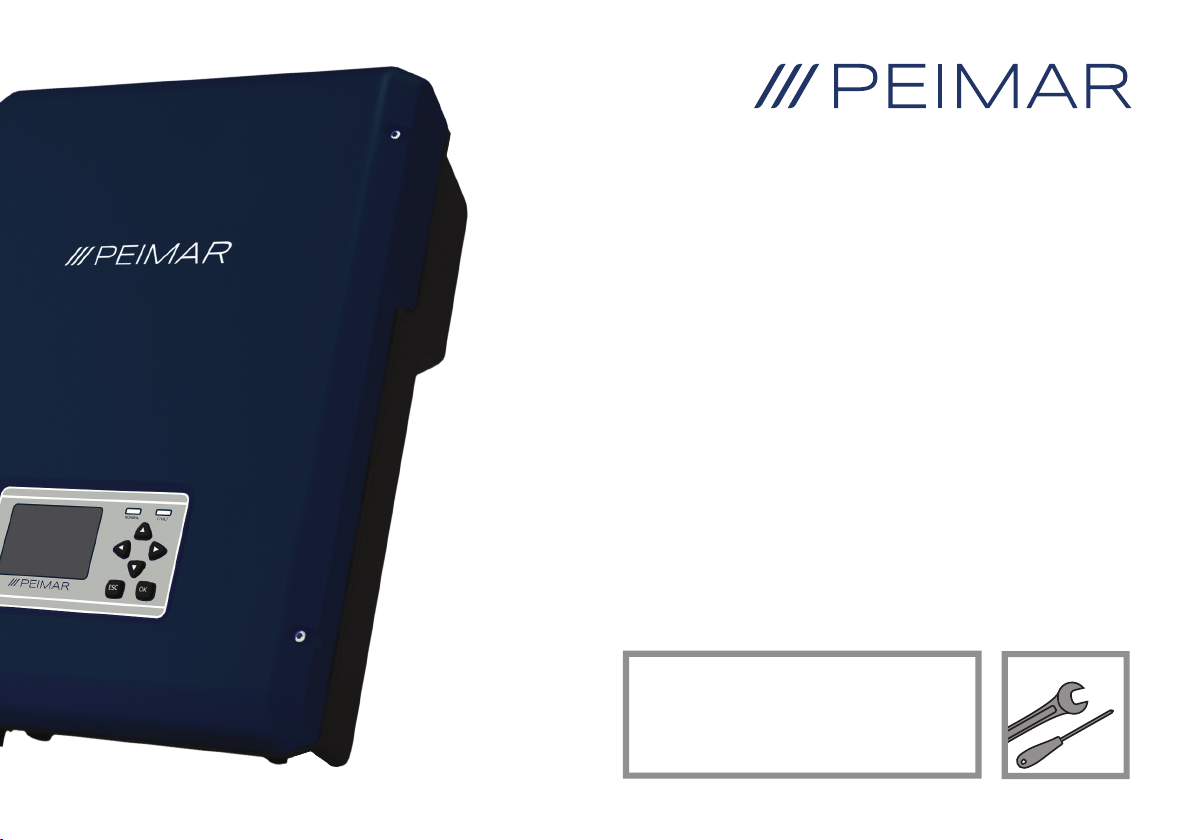
Peimar PSI-3400TLM User manual

1
PSI-3400TLM
PSI-4500TLM
PSI-5200TLM
PSI-6000TLM
MONOPHASE INVERTER
INVERTER MONOFASE
EN / IT

2

1
About this Installation Guide .......... 2
Safety Symbols............................... 3
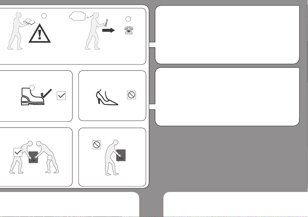
General Safety Requirements ........ 4
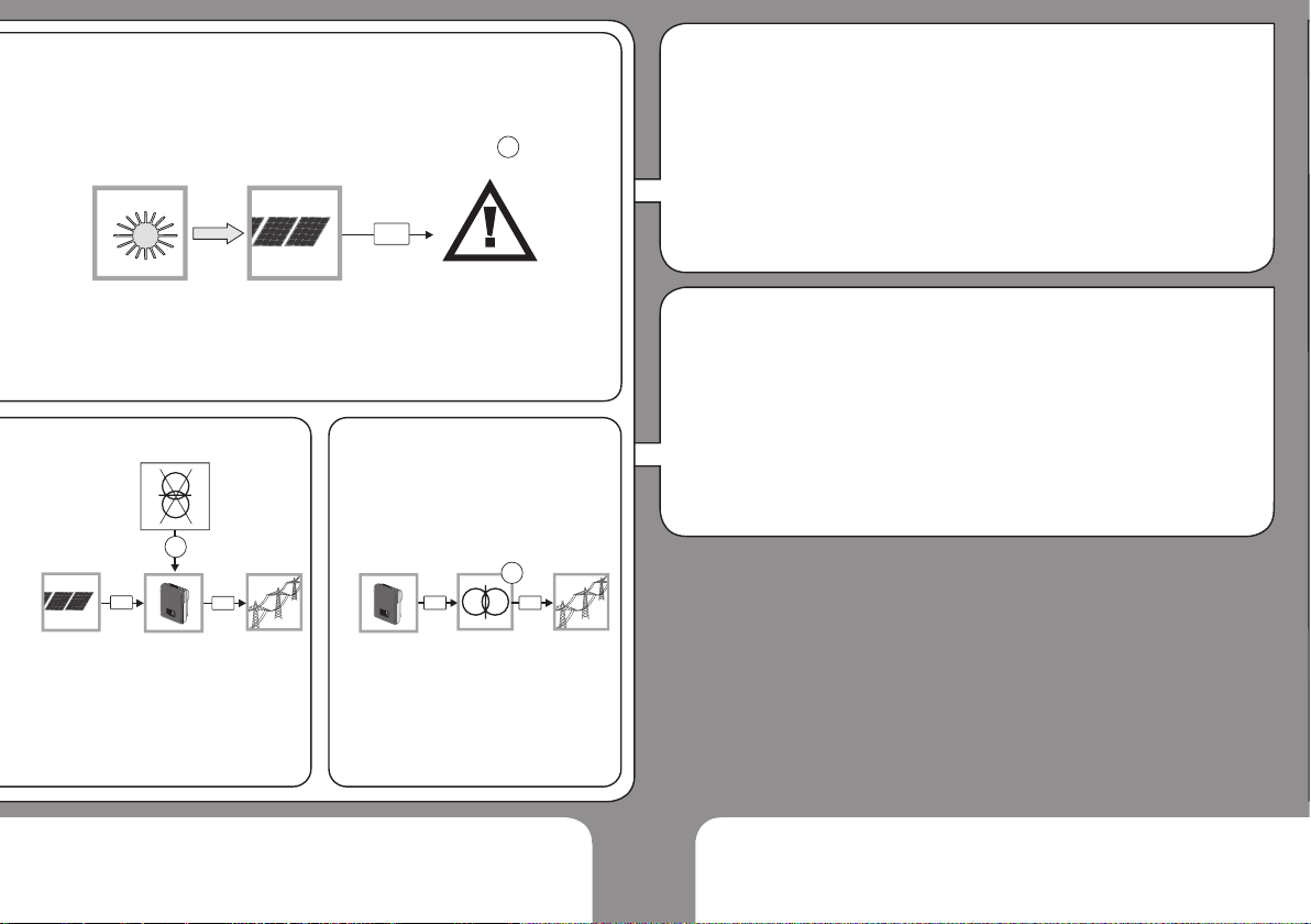
Intended Use .................................. 5
Inverter Function............................. 8
Labels and Markings on
the Inverter ..................................... 9
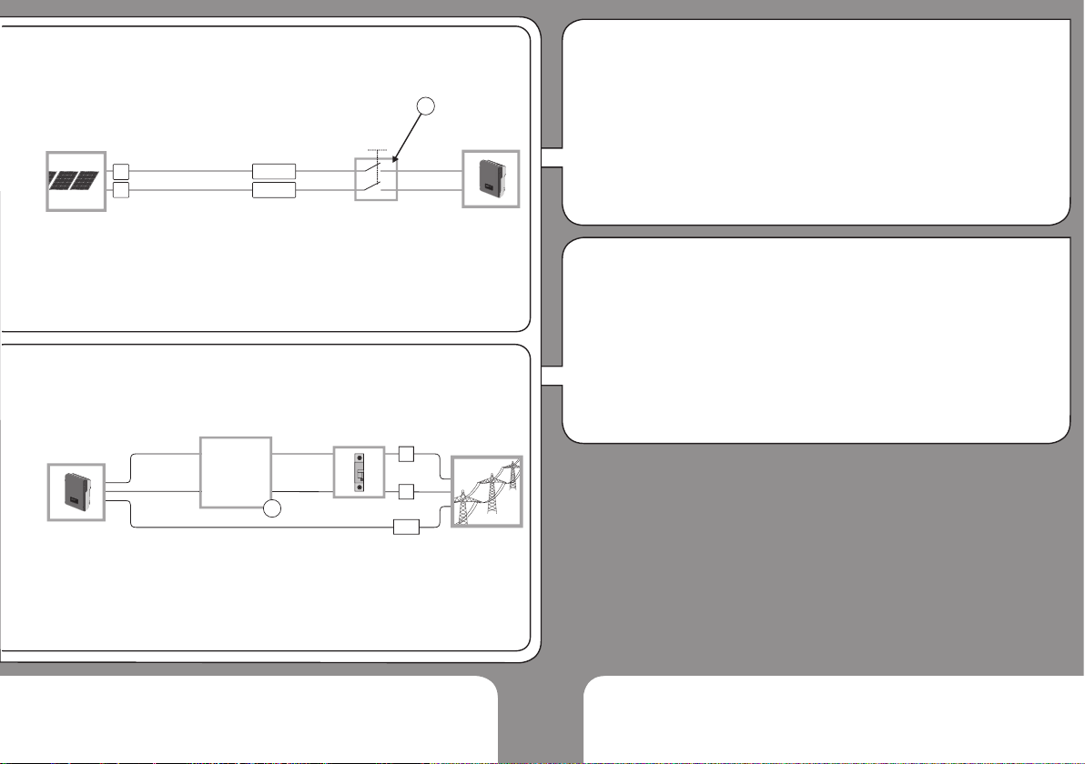
Connections on the Inverter ......... 10
User Interface ...............................11
Unpacking..................................... 12
Mounting the Inverter.................... 14
AC- and DC-Connection............... 17
Starting the Inverter...................... 21
Commissioning............................. 22
Inverter Conguration................... 24
Parallel Connection of PV-Ports ... 25
Opening the Inverter..................... 26
SD Card / Digital Input /
Digital Output................................ 27
Technical Data.............................. 32
Table of Contents
Indice
EN
IT
Informazioni sulle presenti
istruzioni per l’installazione............. 2
Simboli di sicurezza........................ 3
Avvertenze generali di sicurezza.... 4
Uso conforme ................................. 5
Funzionamento............................... 8
Avvertenze e simboli sull’inverter ... 9
Collegamenti................................. 10
Interfaccia utente ......................... 11
Disimballaggio .............................. 12
Montaggio dell’inverter ................. 14
Collegamento AC e DC ................ 17
Avvio dell’inverter ......................... 21
Messa in funzione......................... 22
Congurazione dell’inverter.......... 24
Collegamento in parallelo degli
ingressi ......................................... 25
Come aprire l’inverter ................... 26
Scheda SD / Ingresso digitale /
Uscita digitale ............................... 27
Dati tecnici.................................... 33
1

2
This installation guide describes the
safe installation of the inverters listed
on the left.
Target group:
Qualied technicians
Terms:
Installer Qualied technician
in charge of the
installation
Supplier Company the product
was purchased from
Inverter PV-inverter described
in this installation guide
About this Installation Guide EN
Le presenti istruzioni di installazione
descrivono l’installazione sicura degli
inverter elencati a sinistra.
Gruppo di destinazione:
Tecnici qualicati
Termini:
Installatore Tecnico qualicato che
esegue l’installazione
Fornitore Azienda da cui è stato
acquistato il prodotto
Inverter Inverter fotovoltaico
PSI PEIMAR descritto
nelle presenti istruzioni
per l’uso
Informazioni sulle presenti istruzioni per l’installazione IT
1
2
Normal Fault
OKESC
PSI-3400TLM
Max. DC-Power 3400 W
Max. AC-Power 3200 W
ESC OK
PSI-4500TLM
Max. DC-Power 4500 W
Max. AC-Power 4300 W
ESC OK
PSI-5200TLM
Max. DC-Power 5200 W
Max. AC-Power 5000 W
PSI-6000TLM
Max. DC-Power 6000 W
Max. AC-Power 5750 W
ESC OK
ESC OK

3
Life threatening voltages are
processed inside the inverter.
Hazardous situations that can lead to
death or serious injuries are indicated
with the “WARNING” symbol (1) on
the left.
Hazardous situations that can result in
damage of the inverter are indicated
with the “CAUTION” symbol (2) on the
left.
Countermeasures that must
be taken in order to avoid the
hazardous situation are indicated with
an arrow:
ΓThis is an example how to avoid a
hazardous situation.”
Safety Symbols
1
2
Normal Fault
OKESC
Nell’inverter vengono utilizzate
tensioni mortali.
Situazioni pericolose che possono
causare morte o lesioni gravi
sono contrassegnate dal simbolo
“AVVERTENZA” (1) a sinistra.
Situazioni pericolose che possono
causare danneggiamenti dell’inverter
sono contrassegnate dal simbolo
“CAUTELA” (2) a sinistra.
Contromisure per prevenire
la situazione pericolosa sono
indicate con una freccia:
ΓQuesto è un esempio di come
prevenire una situazione
pericolosa”.
Simboli di sicurezza
EN
IT

4
1. WARNING! Danger of electric
shock!
ÎRead Installation Guide
carefully. Follow all
instructions.
2. Contact your supplier when you
have questions.
3. Wear safety shoes when lifting
and transporting.
4. 2 people are required for
lifting and transporting.
WARNING! Danger of electric
shock and re!
ÎNever modify the inverter except
instructed otherwise by the
manufactured.
Keep this installation guide near the
inverter!
General Safety Requirements EN
?
1
ESCOK
ESCOK
4
2
3
1. AVVERTENZA! Pericolo dovuto
a scossa elettrica!
ÎLeggere attentamente le
istruzioni di installazione.
Seguire tutte le istruzioni.
2. Contattare il proprio fornitore in
caso di dubbi.
3. Indossare scarpe
antinfortunistiche se si sposta o si
trasporta il dispositivo.
4. Il sollevamento e il
trasporto del dispositivo
devono essere effettuati da 2
persone.
AVVERTENZA! Pericolo dovuto a
scossa elettrica e incendi!
ÎQualsiasi modica dell’inverter è
vietata salvo in caso di istruzioni
ricevute dal produttore.
Conservare le presenti istruzioni per
l’installazione vicino all’inverter!
Avvertenze di sicurezza fondamentali IT

5
The inverter (1) converts DC-power
from the PV-generator (2) to AC-
power. The AC-power is fed into the
grid (3). In case of a grid failure: The
inverter automatically disconnects
(4) from the grid. The inverter
automatically reconnects when the
grid is restored. The inverter can
only be used for DC-power from PV-
generators (5).
CAUTION! Risk of damaging
the inverter!
ÎDo not connect other DC-power
sources (6) such as wind power
systems, hydroelectric generators,
fuel cells or batteries.
Intended Use
L’inverter (1) trasforma la potenza
DC del generatore fotovoltaico (2)
in potenza AC. La potenza AC viene
immessa nella rete pubblica (3).
In caso di guasto di rete: L’inverter
si scollega (4) automaticamente
dalla rete. L’inverter si ricollega
automaticamente alla rete quando
essa viene ripristinata. L’inverter può
essere utilizzato solo per la potenza
DC dei generatori fotovoltaici (5).
CAUTELA! Pericolo di
danneggiamento dell’inverter!
ÎAltre fonti di potenza DC (6)
come ad es. centrali eoliche,
idroelettriche, celle a combustibile
o batterie non devono essere
collegate.
Utilizzo conforme
EN
IT

6
1. WARNING! Risk of electric
shock! The PV-panels emit a
dangerous DC-voltage when
exposed to sunlight.
2. The inverter is not
equipped with an internal
isolation transformer
3. Local regulations and standards
can require that an isolation
transformer is additionally
installed. Contact your utility
operator if you have questions.
Electrical Safety EN
DC
1
DC AC
2
AC AC
3
OK
OK
1. AVVERTENZA! Pericolo dovuto
a scossa elettrica! I moduli
fotovoltaici generano tensione DC
pericolosa quando splende il sole.
2. L’inverter non dispone di un
trasformatore di separazione.
3. Le disposizioni e le normative
in vigore possono prevedere
l’impiego di un trasformatore.
Chiedere al proprio gestore di rete.
Sicurezza elettrica IT

7
1. Local regulations and standards
can require that current-breakers
are installed on the DC-side.
Contact your utility operator if you
have questions.
2. The inverter is equipped
with an integrated RCMU
Type B (tested according to EN
62109-2 / IEC 60755). If local
regulations and standards require
an external RCD/RCM, a RCD/
RCM Type A is sufcient.
DC-Disconnect / RCD
DC -
DC+
+
-
1
L
N
PE
RCD
RCM
2
1. Le disposizioni e le normative
in vigore possono prevedere
l’impiego di sezionatori sul lato DC.
Chiedere al proprio gestore di rete.
2. L’inverter è dotato di una RCMU
integrata del tipo B (certicata
secondo EN 62109-2 / IEC 60755).
Nel caso in cui le disposizioni
e le normative locali richiedano
l’installazione di un RCD/RCM
esterno, è sufciente un RCD/RCM
de tipo A.
Dispositivo di sezionamento DC / RCD
EN
IT

8
5
DC2-
DC2+
DC1+
DC1-LN
PE
7
4
3
2
1
6
9
SD
8
RS485
WiFi
12
10
11
1. DC-side surge voltage protection
2. DC-side insulation monitoring
3. DC-side disconnection switch
4. Display, status LEDs, buttons
5. AC-side disconnection relay
6. Grid monitoring
7. AC-side surge voltage protection
8. Digital output port
9. Digital input port
10. Ethernet interface
11. SD card slot
12. WiFi or RS485 interface.
Note: The inverter is equipped
with either WiFi or RS485
communication.
Inverter Function EN
1. Protezione dalla sovratensione
lato DC
2. Monitoraggio dell’isolamento lato DC
3. Sezionatore lato DC
4. Display, LED di stato, tasti
funzione
5. Relè per disconnesione rete AC
6. Monitoraggio di rete
7. Protezione dalla sovratensione
lato AC
8. Uscita digitale
9. Ingresso digitale
10. Interfaccia: WLAN /
Ethernet
11. Slot per scheda SD
12. WLan o interfaccia RS485
Attenzione: L’inverter è dotato di
WLan o di RS485.
Funzionamento dell’inverter IT

9
Type Label:
General Symbols
1. Ensure proper disposal
2. CE-mark
Safety Symbols
3. Read documentation!
4. Warning: Dangerous voltage!
5. Warning: Hot Surfaces!
6. Wait for 5 Minutes before opening!
Bottom of Inverter:
7. DC connection area
8. Ethernet / RS485
9. Wi-antenna
10. Digital I/O connection
11. AC-plug
12. PE-connections
Periodic Inspection:
Check if all markings and safety
symbols are clearly visible on the
inverter. Replace if necessary.
Labels and Markings on the Inverter
Targhetta identicativa:
Simboli generali
1. Smaltire conformemente alle
disposizioni
2. Marchio CE
Simboli di sicurezza
3. Leggere le istruzioni di
installazione!
4. AVVERTENZA! Tensione
pericolosa!
5. Avvertenza! Superci calde!
6. Attendere 5 minuti prima di aprire!
Parte inferiore dell’inverter:
7. Area di collegamento DC
8. Ethernet / RS485
9. Antenna WLan
10. Ingressi e uscite digitali
11. Connettore AC
12. Collegamenti PE
Controllo periodico:
Vericare che tutti i contrassegni e i
simboli di sicurezza sull’inverter siano
ben leggibili. Sostituire i contrassegni
mancanti.
Indicazioni e simboli sull’inverter
EN
IT

10
1. PV-plugs
2. Socket for RS485-cable
3. Socket for ethernet cable
4. Wi-antenna
5. Opening for digital input and
digital output
6. AC-cable plug
7. Connection points for additional
PE-cable
EN
Connections on the Inverter
4
13
2
5
7
7
6
1. Connettore FV
2. Presa per cavo RS485
3. Presa per cavo Ethernet
4. Antenna WLan
5. Apertura per ingresso digitale e
uscita digitale
6. Connettore per cavo AC
7. Collegamento per ulteriore
connessione PE
Collegamenti con l’inverter IT

11
11-04-031012:17
Standard
Today
Total
5
hours
14.6
kwh
52.7
kwh
5
hours
1
minutes
<>to Main MenuESC
15.21kw 14.60kw
Normal
49.99Hz
12
3
6
5
4
1. Green LED (“Normal”):
- On = Normal operation;
- Flashing = Waiting, checking or
starting up;
- Off = Possible failure.
2. Red LED (Fault”):
- On = Failure;
- Flashing = Temporary failure;
- Off = Normal operation.
3. ESC-Key
Press ESC-key in order to exit
current screen
4. OK-Key
Press OK-key in order to
conrm entry.
5. Cursor-Keys:
Press the cursor keys to navigate
the menu and to increase or
decrease values.
6. LCD
The default password is for
changing the settings is“111111”
User Interface EN
1. LED verde (“Normale”):
- Acceso = funzionamento
normale;
- Lampeggiante = in attesa,
verica in corso
o in avviamento,
- Spento = possibile errore
2. LED rosso (“Fault”):
- Acceso = errore
- Lampeggiante = errore
temporaneo
- Spento = funzionamento normale
3. Tasto ESC
Premere il tasto ESC per
uscire dalla schermata.
4. Tasto OK
Premere il tasto OK per
confermare l’inserimento.
5. Tasti del cursore:
Premere i tasti del cursore per
navigare nel menu ed aumentare
o diminuire i valori.
6. LCD
La password predenita per le
impostazioni avanzate è “111111”.
Interfaccia utente IT

12
Proceed as follows:
1. Check the packaging for
damages.
2. Contact your supplier in case
packaging is damaged.
3. Unpack the inverter. Check if
the items of the packing list are
included. The scope of delivery is
listed on the following page
4. Check the items for visible
damages.
5. Contact your supplier when
items are missing or the inverter
is damaged. Do not install a
damaged inverter.
Keep packaging for later use.
Unpacking EN
Procedere come segue:
1. Vericare che l’imballaggio non
sia danneggiato.
2. Contattare il proprio fornitore
qualora l’imballaggio fosse
deteriorato.
3. Disimballare l’inverter. Vericare
la presenza di tutti i componenti.
L’elenco dei componenti forniti è
illustrato nella pagina successiva.
4. Vericare che il tutto non
sia danneggiato.
5. Contattare il proprio fornitore
qualora manchi qualcosa o in
caso di danni. Non utilizzare mai
un inverter danneggiato.
Conservare la confezione per
l’utilizzo successivo.
Disimballaggio IT

13
The following tools are required for
the installation of the inverter:
1. Cable stripping tool for cables
(e.g. PV-AZM)
2. Drill
3. Multimeter
4. Hex key
5. Pencil
6. Screwdriver
7. Hammer
8. Level
EN
Required Tools
1
2
7 865
3
4
Per installare l’inverter sono
necessari i seguenti strumenti:
1. Pinza spelali per cavo DC (ad
es. PV-AZM)
2. Trapano
3. Multimetro
4. Brugola
5. Matita
6. Cacciavite
7. Martello
8. Livella ad acqua
Strumenti Necessari IT

14
Requirements for the installation
location are specied on the following
pages.
Proceed as follows:
1. On plasterboard walls: Use center
holes. Screw wall mounting
bracket to wall stud.
2. On massive walls: Use outside
holes. Screw wall mounting
bracket to wall. Screw wall
mounting bracket to wall.
3. Hang inverter on wall
mounting bracket.
4. Check correct position.
5. Optional: Secure the inverter with
a padlock or screw.
EN
Mounting the Inverter
5
PV1+PV1+ PV1- PV1- PV2+ PV2+PV2- PV2- 321
T+T- R+R-
LOCK
12
34
ESCOK
ESCOK
ESCOK
Le condizioni del luogo di montaggio
sono riportate nelle pagine seguenti:
Procedere come segue:
1. Su lastre di cartongesso:
Utilizzare i fori centrali. Avvitare il
supporto a parete sulla listellatura.
2. Su pareti massicce: Utilizzare i fori
esterni. Avvitare il supporto sulla
parete.
3. Appendere l’inverter al
supporto a parete.
4. Vericare la corretta sede.
5. Opzionale: Proteggere da furti con
un lucchetto o una vite.
Montaggio dell’inverter IT

15
52.0 cm
38.0 cm 17.5 cm
18.5 cm
18.0 cm
24 kg
11.5 cm
11-04-03 1012:17
Standard
Today
Total
5
hours
14.6
kwh
52.7
kwh
5
hours
1
minutes
<>to Main MenuESC
15.21kw 14.60 kw
Normal
49.99 Hz
11-04-031012:17
Standard
Today
Total
5
hours
14.6
kwh
52.7
kwh
5
hours
1
minutes
<>to Main MenuESC
15.21kw 14.60kw
Normal
49.99Hz
23.0 cm
6 mm
min.
30 cm
min.
30 cm
min.
30 cm
min.
30 cm
ESCOK ESCOK ESCOK

16
ESC OK
ESCOK
ESCOK
< +45 °C
> -20 °C
< 95 %
> +45 °C
< -20 °C
> 95 %
< 25 °
ESCOK
ESC OK
ESCOK
ESCOK
ESC OK
ESCOKESC OK

17
1. Use suitable circuit breaker.
2. WARNING! Risk of re!
ÎDo not connect any consumers
to the AC-line.
3. Recommendation: Keep
cable losses below 1 %. Keep
impedance below 0.2 Ohm.
4. Observe values for wire
sizes.
5. In France: Use a PE-connection
with a minimum cross section
of 6 or 16 mm2Cu.
EN
AC-Connection - Requirements
L1
N
PE
L1
N
PE
2
3
FR PE: < 10 m: 6 mm Cu
2
> 10 m: 16 mm Cu
2PE
5
1
10 mm - 14 mm
4
ESC OK
ESCOK
1. Utilizzare un interruttore
magnetotermico appropriato.
2. AVVERTENZA! Pericolo dovuto
ad incendio!
ÎNon collegare alcuna utenza al
cavo AC.
3. Raccomandazione: mantenere la
dispersione di potenza al di sotto
dell’1%. Mantenere l’impedenza al
di sotto di 0,2 ohm.
4. Prestare attenzione
ai valori relativi alle
dimensioni dei cavi.
5. In Francia: Utilizzare un
raccordo di PE con una sezione
di almeno 6 - 16 mm2Cu.
Collegamento AC – Condizioni IT

18
WARNING! Risk of electric shock!
ÎDeactivate AC-voltage when
connecting the AC-cable.
Proceed as follows:
1. Disconnect voltage.
2. Check that no voltage is present.
3. Prevent accidental reconnection
4. Strip cable as specied in the
illustration.
5. Remove swivel nut and
shove swivel nut over the
cable.
6. Attach wires to AC-terminal.
7. Push plug into sleeve.
8. Tighten swivel nut.
9. In France: Use an additional
PE-connection with a minimum
cross section of 6 - 16 mm2Cu.
Connection of the AC Cable
L
N
PE
2
0 V ?
3
4
5
6
7
8
1
7mm20 mm
25 mm
8
AVVERTENZA! Pericolo dovuto a
scossa elettrica!
ÎDisattivare la tensione AC prima di
collegare il cavo AC.
Procedere come segue:
1. Staccare la tensione.
2. Accertarsi che non sia presente
tensione.
3. Prevenire ed evitare la
riaccensione accidentale
4. Spelare il cavo come descritto.
5. Svitare il dado di raccordo
e spingere sul cavo.
6. Collegare il cavo AC al morsetto
AC.
7. Spingere il cavo nel manicotto.
8. Serrare il dado di raccordo.
9. In Francia: Utilizzare un
raccordo di PE con una sezione
di almeno 6 - 16 mm2Cu.
Collegamento del cavo AC
EN
IT
DC2-
DC2+
DC1+
DC1-
+
-
+
-
65
MPPT
MPPT
3
2 2
+
-
+
-
VV
MAX < 550 DC
1
DC2-
DC2+
DC1+
DC1-
+
-
+
-
4
ESC OK
ESC OK
ESC OK
This manual suits for next models
3
Table of contents
Other Peimar Inverter manuals
Popular Inverter manuals by other brands

Kramer
Kramer SG-6006 user manual

AirMan
AirMan SG instruction manual

Generac Power Systems
Generac Power Systems GUARDIAN 04136-0 owner's manual

Vector
Vector POCKET POWER VEC041 User's manual & warranty information

Rigol
Rigol DG900 Series Service guide

Mitsubishi
Mitsubishi FR-A500 Series instruction manual